Raspberry Pi 2 & 3 Pin Mappings
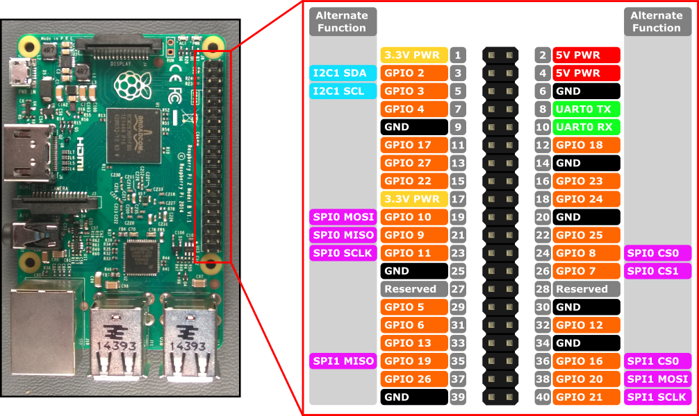
Hardware interfaces for the Raspberry Pi 2 and Raspberry Pi 3 are exposed through the 40-pin header J8 on the board. Functionality includes:
- 24x - GPIO pins
- 1x - Serial UARTs (RPi3 only includes mini UART)
- 2x - SPI bus
- 1x - I2C bus
- 2x - 5V power pins
- 2x - 3.3V power pins
- 8x - Ground pins
GPIO Pins
Let's look at the GPIO available on this device.
GPIO Pin Overview
The following GPIO pins are accessible through APIs:
GPIO# Power-on Pull Alternate Functions Header Pin 2 PullUp I2C1 SDA 3 3 PullUp I2C1 SCL 5 4 PullUp 7 5 PullUp 29 6 PullUp 31 7 PullUp SPI0 CS1 26 8 PullUp SPI0 CS0 24 9 PullDown SPI0 MISO 21 10 PullDown SPI0 MOSI 19 11 PullDown SPI0 SCLK 23 12 PullDown 32 13 PullDown 33 16 PullDown SPI1 CS0 36 17 PullDown 11 18 PullDown 12 19 PullDown SPI1 MISO 35 20 PullDown SPI1 MOSI 38 21 PullDown SPI1 SCLK 40 22 PullDown 15 23 PullDown 16 24 PullDown 18 25 PullDown 22 26 PullDown 37 27 PullDown 13 35* PullUp Red Power LED 47* PullUp Green Activity LED
* = Raspberry Pi 2 ONLY. GPIO 35 & 47 are not available on Raspberry Pi 3.
GPIO Sample
As an example, the following code opens GPIO 5 as an output and writes a digital '1' out on the pin:
using Windows.Devices.Gpio;

public void GPIO()
{
    // Get the default GPIO controller on the system
    GpioController gpio = GpioController.GetDefault();
    if (gpio == null)
        return; // GPIO not available on this system

    // Open GPIO 5
    using (GpioPin pin = gpio.OpenPin(5))
    {
        // Latch HIGH value first. This ensures a default value when the pin is set as output
        pin.Write(GpioPinValue.High);

        // Set the IO direction as output
        pin.SetDriveMode(GpioPinDriveMode.Output);

    } // Close pin - will revert to its power-on state
}
When you open a pin, it will be in its power-on state, which may include a pull resistor. To disconnect the pull resistors and get a high-impedance input, set the drive mode to GpioPinDriveMode.Input:
pin.SetDriveMode(GpioPinDriveMode.Input);
When a pin is closed, it reverts to its power-on state.
Pin Muxing
Some GPIO pins can perform multiple functions. By default, pins are configured as GPIO inputs. When you open an alternate function by calling I2cDevice.FromIdAsync() or SpiDevice.FromIdAsync() , the pins required by the function are automatically switched ("muxed") to the correct function. When the device is closed by calling I2cDevice.Dispose() or SpiDevice.Dispose(), the pins revert back to their default function. If you try to use a pin for two different functions at once, an exception will be thrown when you try to open the conflicting function. For example,
var controller = GpioController.GetDefault();
var gpio2 = controller.OpenPin(2);      // open GPIO2, shared with I2C1 SDA

var dis = await DeviceInformation.FindAllAsync(I2cDevice.GetDeviceSelector());
var i2cDevice = await I2cDevice.FromIdAsync(dis[0].Id, new I2cConnectionSettings(0x55)); // exception thrown because GPIO2 is open

gpio2.Dispose(); // close GPIO2
var i2cDevice = await I2cDevice.FromIdAsync(dis[0].Id, new I2cConnectionSettings(0x55)); // succeeds because gpio2 is now available

var gpio2 = controller.OpenPin(2); // throws exception because GPIO2 is in use as SDA1

i2cDevice.Dispose(); // release I2C device
var gpio2 = controller.OpenPin(2); // succeeds now that GPIO2 is available
Serial UART
There is one Serial UART available on the RPi2/3: UART0
- Pin 8 - UART0 TX
- Pin 10 - UART0 RX
The example below initializes UART0 and performs a write followed by a read:
using Windows.Storage.Streams;
using Windows.Devices.Enumeration;
using Windows.Devices.SerialCommunication;

public async void Serial()
{
    string aqs = SerialDevice.GetDeviceSelector("UART0");                   /* Find the selector string for the serial device   */
    var dis = await DeviceInformation.FindAllAsync(aqs);                    /* Find the serial device with our selector string  */
    SerialDevice SerialPort = await SerialDevice.FromIdAsync(dis[0].Id);    /* Create an serial device with our selected device */

    /* Configure serial settings */
    SerialPort.WriteTimeout = TimeSpan.FromMilliseconds(1000);
    SerialPort.ReadTimeout = TimeSpan.FromMilliseconds(1000);
    SerialPort.BaudRate = 9600;                                             /* mini UART: only standard baud rates */
    SerialPort.Parity = SerialParity.None;                                  /* mini UART: no parities */
    SerialPort.StopBits = SerialStopBitCount.One;                           /* mini UART: 1 stop bit */
    SerialPort.DataBits = 8;

    /* Write a string out over serial */
    string txBuffer = "Hello Serial";
    DataWriter dataWriter = new DataWriter();
    dataWriter.WriteString(txBuffer);
    uint bytesWritten = await SerialPort.OutputStream.WriteAsync(dataWriter.DetachBuffer());

    /* Read data in from the serial port */
    const uint maxReadLength = 1024;
    DataReader dataReader = new DataReader(SerialPort.InputStream);
    uint bytesToRead = await dataReader.LoadAsync(maxReadLength);
    string rxBuffer = dataReader.ReadString(bytesToRead);
}
Note that you must add the following capability to the Package.appxmanifest file in your UWP project to run Serial UART code:
Visual Studio 2017 has a known bug in the Manifest Designer (the visual editor for appxmanifest files) that affects the serialcommunication capability. If your appxmanifest adds the serialcommunication capability, modifying your appxmanifest with the designer will corrupt your appxmanifest (the Device xml child will be lost). You can work around this problem by hand editing the appxmanifest by right-clicking your appxmanifest and selecting View Code from the context menu.
  <Capabilities>
    <DeviceCapability Name="serialcommunication">
      <Device Id="any">
        <Function Type="name:serialPort" />
      </Device>
    </DeviceCapability>
  </Capabilities>
I2C Bus
Let's look at the I2C bus available on this device.
I2C Overview
There is one I2C controller I2C1 exposed on the pin header with two lines SDA and SCL. 1.8KΩ internal pull-up resistors are already installed on the board for this bus.
Signal Name Header Pin Number Gpio Number SDA 3 2 SCL 5 3
The example below initializes I2C1 and writes data to an I2C device with address 0x40:
using Windows.Devices.Enumeration;
using Windows.Devices.I2c;

public async void I2C()
{
    // 0x40 is the I2C device address
    var settings = new I2cConnectionSettings(0x40);
    // FastMode = 400KHz
    settings.BusSpeed = I2cBusSpeed.FastMode;

    // Create an I2cDevice with the specified I2C settings
    var controller = await I2cController.GetDefaultAsync();

    using (I2cDevice device = controller.GetDevice(settings))
    {
        byte[] writeBuf = { 0x01, 0x02, 0x03, 0x04 };
        device.Write(writeBuf);
    }
}
SPI Bus
There are two SPI bus controllers available on the RPi2/3.
SPI0
Signal Name Header Pin Number Gpio Number MOSI 19 10 MISO 21 9 SCLK 23 11 CS0 24 8 CS1 26 7
SPI1
Signal Name Header Pin Number Gpio Number MOSI 38 20 MISO 35 19 SCLK 40 21 CS0 36 16
SPI Sample
An example of how to perform a SPI write on bus SPI0 using chip select 0 is shown below:
using Windows.Devices.Enumeration;
using Windows.Devices.Spi;

public async void SPI()
{
    // Use chip select line CS0
    var settings = new SpiConnectionSettings(0);
    // Set clock to 10MHz
    settings.ClockFrequency = 10000000;

    // Get a selector string that will return our wanted SPI controller
    string aqs = SpiDevice.GetDeviceSelector("SPI0");

    // Find the SPI bus controller devices with our selector string
    var dis = await DeviceInformation.FindAllAsync(aqs);

    // Create an SpiDevice with our selected bus controller and Spi settings
    using (SpiDevice device = await SpiDevice.FromIdAsync(dis[0].Id, settings))
    {
        byte[] writeBuf = { 0x01, 0x02, 0x03, 0x04 };
        device.Write(writeBuf);
    }
}