Step-by-step for deploying a SDNv2 using VMM - Part 4
In this post, we will walk through the steps to deploy gateways with VMM. Different from the official guide, besides provide the step-by-step guide, I will also include configuration steps on Enterprise Gateway (a Windows Server 2012 R2 RRAS VM in my setup). Here is the link to the official guide.
Understand IPsec and GRE Gateway in Windows Server 2016
Before you start deployment, I would suggest you review the following links.
- GRE Tunneling in Windows Server Technical Preview
- RAS Gateway Deployment Architecture
- RAS Gateway High Availability
- Leverage GRE Tunneling to enable the multi-tenant direct routing on Windows Server Gateway
IPSec
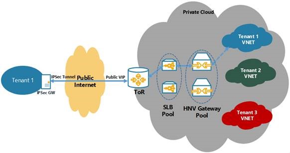
This is what an IPSec configuration looks like logically
- The Top-of-the-Rack switch (or BGP Router in Provider Address space / Private Cloud fabric) is connected to SLB
- ToR actually has a BGP Peering setup with SLB MUXes to learn all the SLB VIPs that need to be advertised to public network (internet)
- Tenant’s Enterprise GW connects to this Public VIP and SLB MUX will internally translate it to DIP Address which will belong to one of the Gateway VMs (GW VM’s Transit IP Address)
For this topology, you need to have the BGP Peering setup between ToR and SLB. VMM automatically configures the BGP Peering on SLB when you specify the corresponding information to LB Manager. However, ToR needs to be manually setup to accept connections from SLB MUX VMs.
Once all this is configured, specifying a Public IP Address from the Public VIP Pool in Gateway Manager configuration will cause SLB MUXs to advertise that VIP to ToR and eventually make it available on public network so that enterprise Gateway can come and connect via IPSec S2S VPN.
GRE
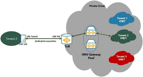
For GRE, the SLB is out of the picture and the logical topology looks like this
- The only difference here is that Gateway VMs will directly peer with ToR and advertise their own GRE VIPs
- ToR again needs to be configured to accept connections from all possible Gateway VM Transit IP Addresses.
L3
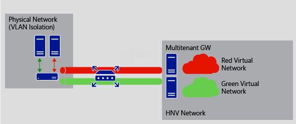
For Enterprises that deploy an on-premises private cloud, L3 Gateway can act as a forwarding gateway and route traffic between virtual networks and the physical network. For example, if you have created virtual networks for your R&D department, but there are some key resources (e.g., a hardware appliance, etc.) on your physical network, L3 Gateway can route traffic between the virtual network and the physical network to provide users working on the virtual network with all of the services that they need.
In the illustration below, the physical and virtual networks are at the same physical location. L3 Gateway is used to route traffic between the physical network and virtual networks.
BGP Routing at Enterprise GW
This BGP Routing is in Customer Address space and is completely different from the ones listed above (in PA space). This BGP config is totally optional and if you don’t have it in your setup, then static routes will work just fine.
Create GRE VIP logical network required for gateway deployment
You need an IP address pool for private VIPs and to assign virtual IP address to GRE endpoints. You will create a GRE VIP Logical network to configure an IP address pool for GRE endpoints.
The GRE VIP network is a subnet that exists solely for defining VIPs that are assigned to gateway virtual machines running on your SDN fabric for a S2S GRE connection type. This network does not need to be pre-configured in your physical switches or router and need not have a VLAN assigned.
Create the GRE VIP logical network
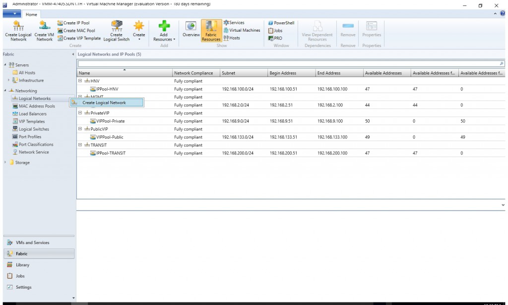
- From the VMM console, start the Create Logical Network Wizard.
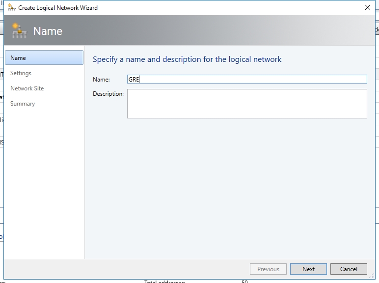
- Type a name and optional description for this network and click Next.
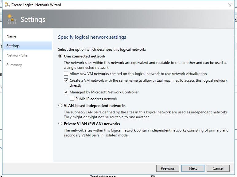
- On the Settings page, ensure you select One Connected Network. Optionally, you can also check Create a VM network with the same name box to allow virtual machines to access this logical network directly and the Managed by the Network Controller box then click Next.
- On the Network Site panel, add the network site information for your VIP subnet. This should include the Host Group and subnet information for your VIP network.

- Review the Summary information and complete the Logical Network wizard
Create an IP pool for GRE VIP addresses
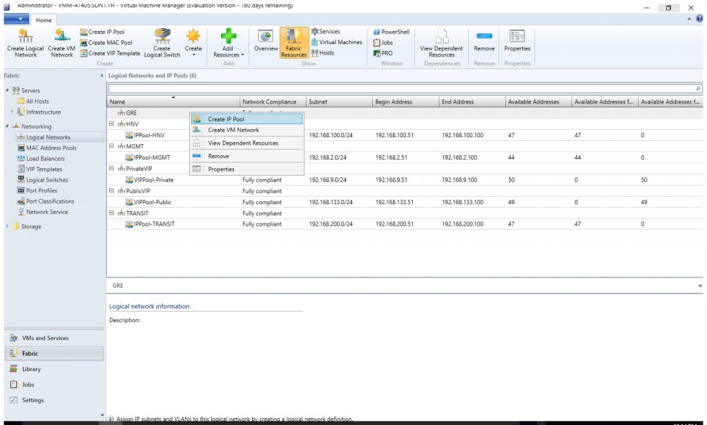
- Right-click the GRE VIP logical network in VMM and select Create IP Pool from the drop down menu.
- Type a name and optional description for the IP Pool and ensure that the VIP network is selected for the logical network. Click Next.
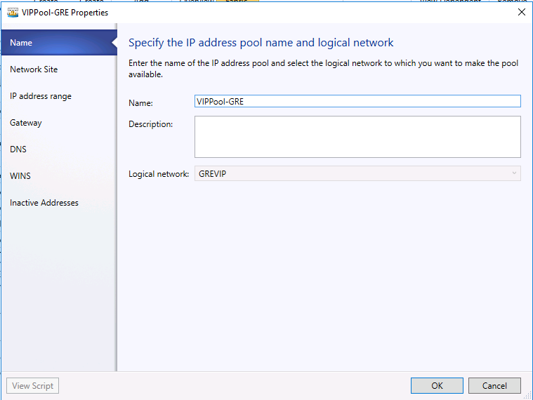
- Accept the default network site and click Next.

- Choose a starting and ending IP address for your range.
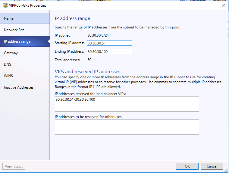
 Important
Start your range on the fourth addresses of your available subnet. For example, if your available subnet is from .1 to .254, start your range at .4. - In the IP addresses reserved for load balancer VIPs box, type the IP addresses range in the subnet. This should match the range you used for starting and ending IP addresses.
- You do not need to provide gateway, DNS or WINS information as this pool is used to allocate IP addresses for VIPs only via the network controller, so click Next to skip these screens.
- Review the summary information and complete the wizard.
Deploy Gateway Service
- In VMM, navigate to the Library.
- In the top of the left pane, in the Templates section, select Service Templates.
- In the ribbon at the top, click Import Template.
- Browse to your service template folder, select EdgeServiceTemplate Generation2.xml and click Next.
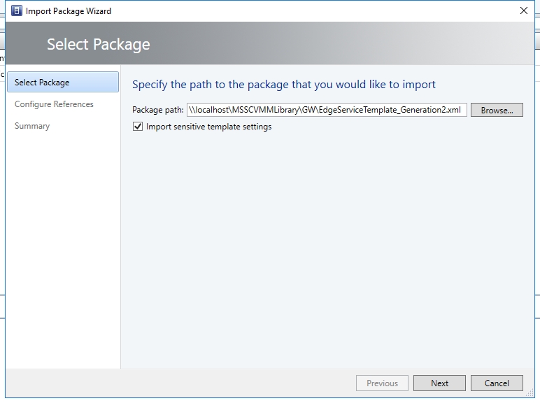
- Update the parameters to reflect the your environment configuration .
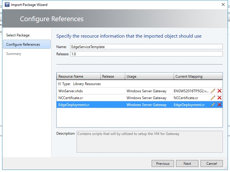
- Click Next.
- On the Summary page, click Import.
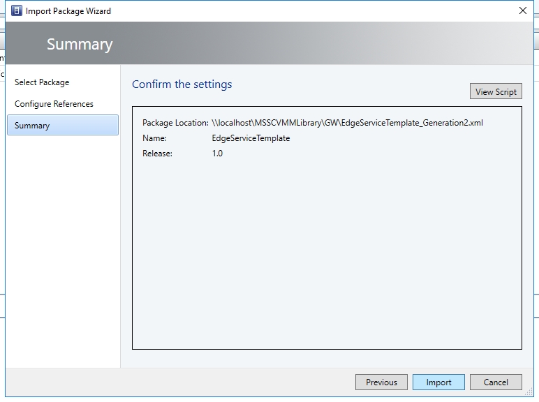
- Same as the pervious blog, if your syspreped image is based on volume license image, you may jump to the step 12.
- (Optional) If your syspreped image is not based on volume license image, we need to modify the service template and input the product key. You may right click the template and select "Open Designer".
- Then right click "Windows Server Gateway" and select "Properties".
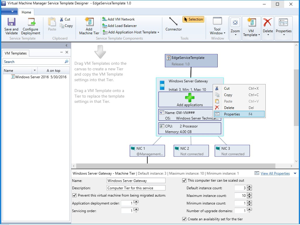
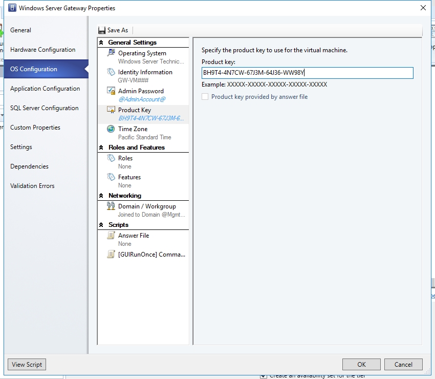
- On "OS Configuration" page, input the product key.
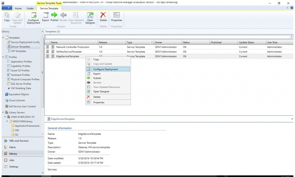
- Select the EdgeServiceTemplate Generation2.xml service template and click Configure Deployment to begin. Type a name and choose a destination for the service instance. The destination must map to a Host Group that contains the hosts configured previously for gateway deployment purposes.
- Give the service a name.

- Click OK.
- On the left side of the Configure Deployment window, there are a number of settings that you must configure.

- After you configure these settings, you can click Deploy Service to begin the service deployment job. Deployment times will vary depending on your hardware but are typically between 30 and 60 minutes.
- You may check the result of the deployment and make sure it's successful.
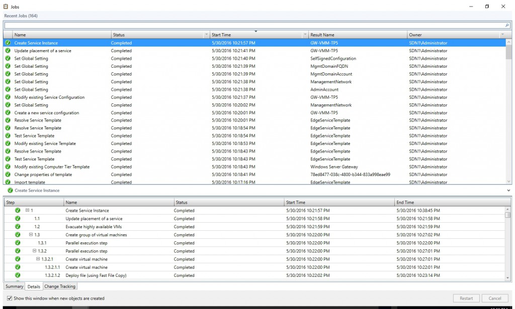
Configure the Gateway Manager Role
- Open the Fabric workspace.
- Click Network Service to display the list of network services installed.
- Right-click your network controller service and select Properties.
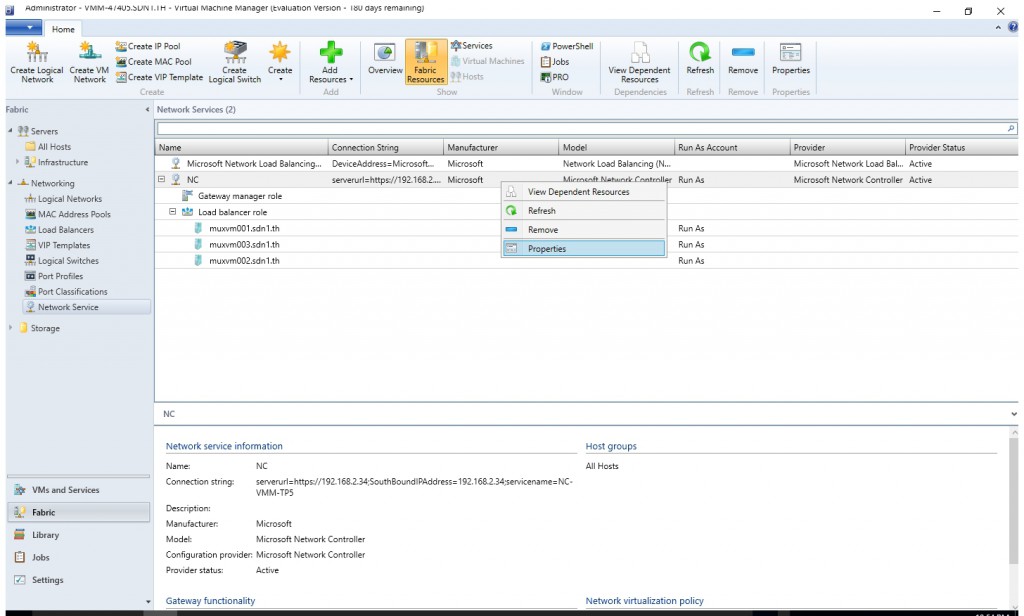
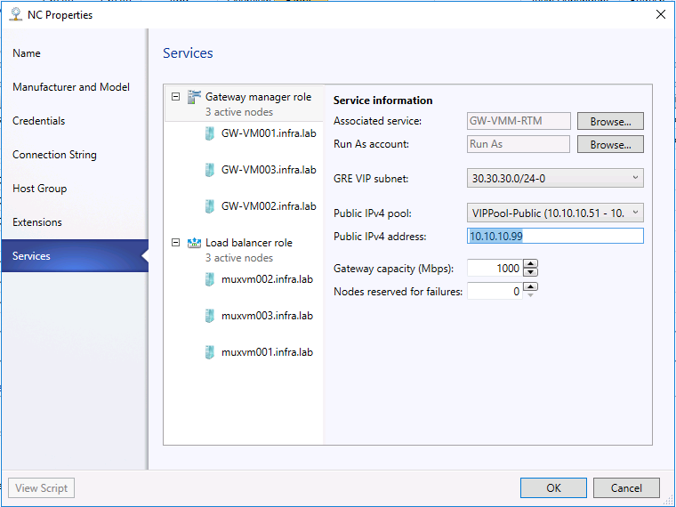
- Click the Services tab and select the Gateway Manager Role in the services panel.

- Find the Associated Service field under Service information and click Browse.
- Select the gateway service instance you created earlier and click OK.
- Public IPv4 address, provide an IP address from the previous pool, and ensure you don’t select the initial 3 IP addressed from the range. In my case, I used 192.168.133.99. (192.168.133.100 had already been used as VIP of SLB in my previous test.)In Public IPv4 pool, select the Public IP Pool you configured during the SLB deployment. You will use the IP as the destination IP on the Enterprise gateway.
- In GRE VIP subnet, select the VIP subnet that you created previously.
- Select the Run As account that will be used by network controller to access the gateway virtual machines.
- On each node's configuration page, select the IPv4 Frontend Subnet.
- Specify the local ASN.
- Add the peering device info for the BGP peer.


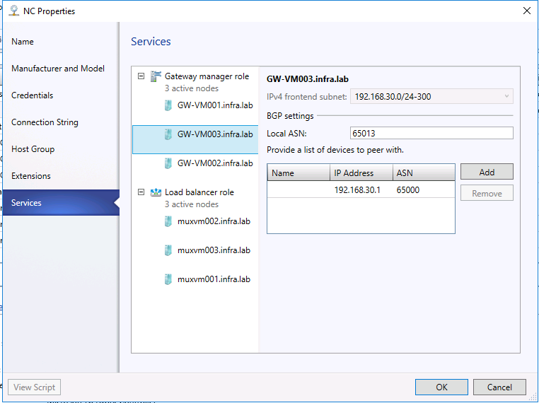
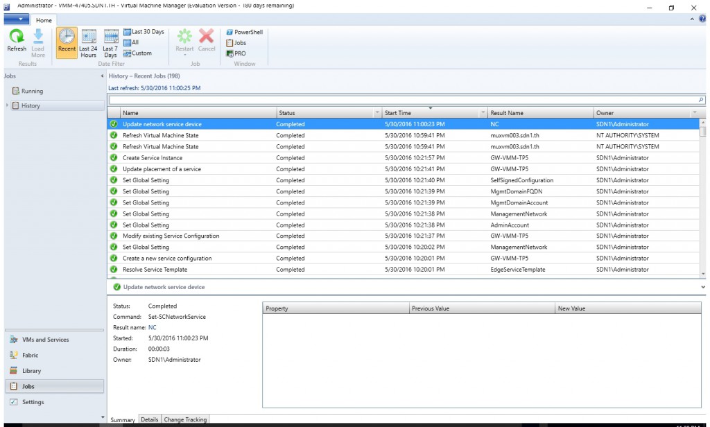
- Click OK. Then check the job "Update network service device" complete successfully.
Configure BGP Router
Run the script below to add the BGP Peers and Custom Route and make sure all the BGP Peers are connected.
 add-bgppeer -Name GW01 -LocalIPAddress 192.168.30.1 -PeerIPAddress 192.168.30.56 -LocalASN 65000 -PeerASN 65011 -OperationMode Mixed -PeeringMode Automatic
add-bgppeer -Name GW02 -LocalIPAddress 192.168.30.1 -PeerIPAddress 192.168.30.55 -LocalASN 65000 -PeerASN 65012 -OperationMode Mixed -PeeringMode Automatic
add-bgppeer -Name GW03 -LocalIPAddress 192.168.30.1 -PeerIPAddress 192.168.30.54 -LocalASN 65000 -PeerASN 65013 -OperationMode Mixed -PeeringMode Automatic
get-bgppeer
Please also use the cmdlet below to check if the VIP (10.10.10.99) had already been advised to BGP router.
Get-BgprouteInformation -type all
Validation
After you deploy the gateway using the VMM template, you can configure S2S GRE, S2S IPSec, or L3 connection types and validate a successful Gateway deployment.
Test Case 4: S2S IPSec connection
A S2S IPSec connection allows you to securely access remote virtual machines and services from your datacenter. Use the following steps to create a S2S IPSec connection. In my case, I had already create a VM network called "VNET-IPSEC" (12.0.0.0/24) and create a VM "TESTVMIPSEC" (12.0.0.4)) in that VM network.
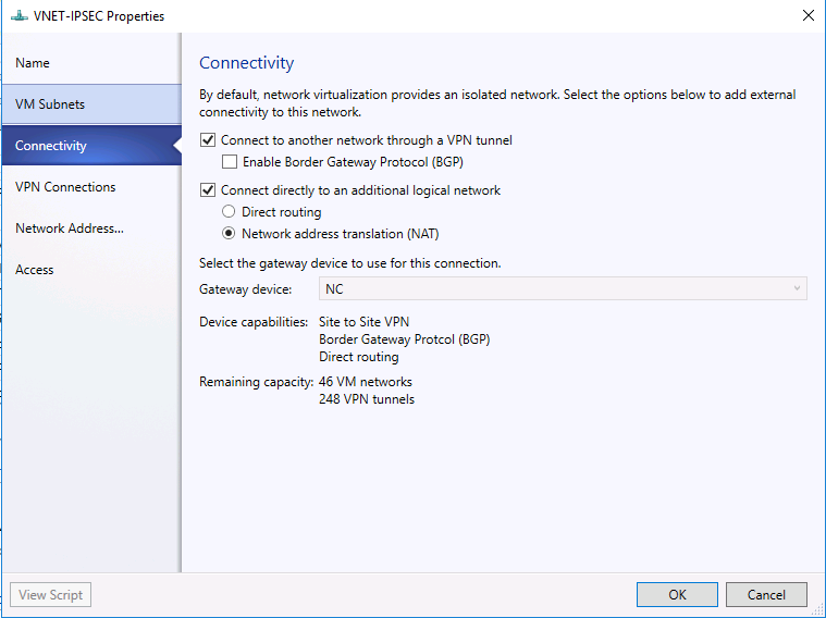
- Open the properties dialog window of an existing VM Network called "VNET-IPSEC".
- On connectivity page and select the checkbox "Connect to another network through a VPN tunnel". (Optional) You may also enable NAT for that VM network if you want the VM in that VM network to be able to access external network.
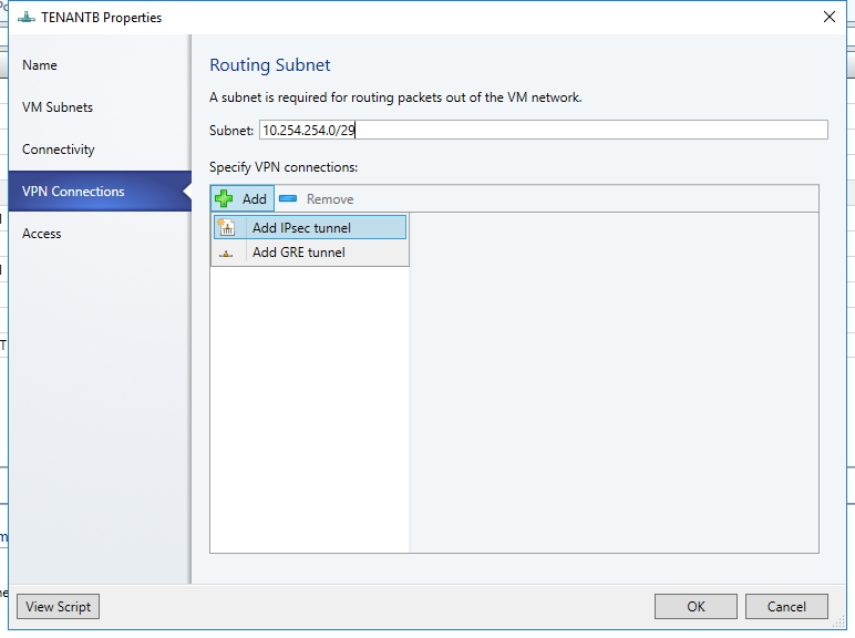
- Select the VPN Connections tab.
- Type a subnet as shown in the following diagram. This subnet is used to route packets out of the VM Network. This subnet need not be pre-configured in your datacenter.Click Add and select the IPSec type connection.
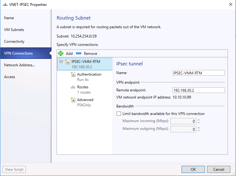
- Give the connection a name (e.g., IPSEC-VMM-RTM).
- Type the IP address of the Remote endpoint. In my setup, it's 192.168.30.2, which is the remote IPSec gateway's external IP.
- Select the Authentication tab.
- Choose your preferred authentication method for the connection. If you choose the authentication using ‘Run As Account’, then you need to create a user account with the username of your choice and the IPSec key as the password for the account. Browse and select this account as your Run As Account. In my case, I use the account "Run As". The account's password will be used as IPsec key.

- Select the Routes tab and Type all the remote subnets that you need to connect to.

- You may accept the default setting on Advanced tab. Then click "OK".

- Make sure the VPN connection for VM Network gateway had already been added successfully.
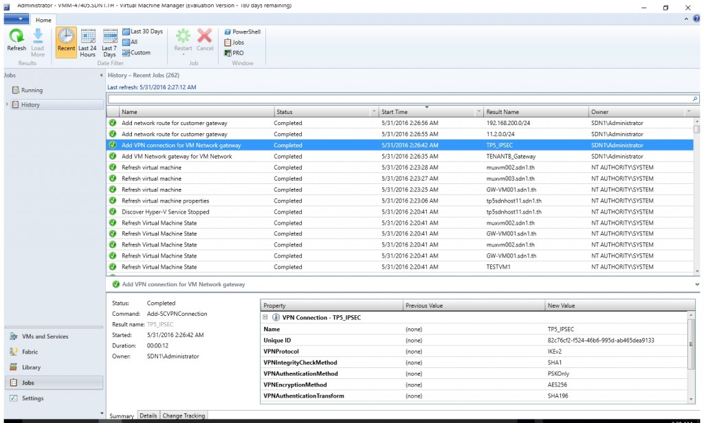
- Different from Windows Server 2012 R2, on Windows Server 2016, all the IPSec VPN will share the same external IP, which is the public IP (VIP) you configured on the Gateway Service page of Network Controller's properties dialog window. You cannot see it from individual VM Network's properties any more.

Now go to the Enterprise Gateway VM. In my case, I used an existing Windows Server 2012 R2 RRAS VM.
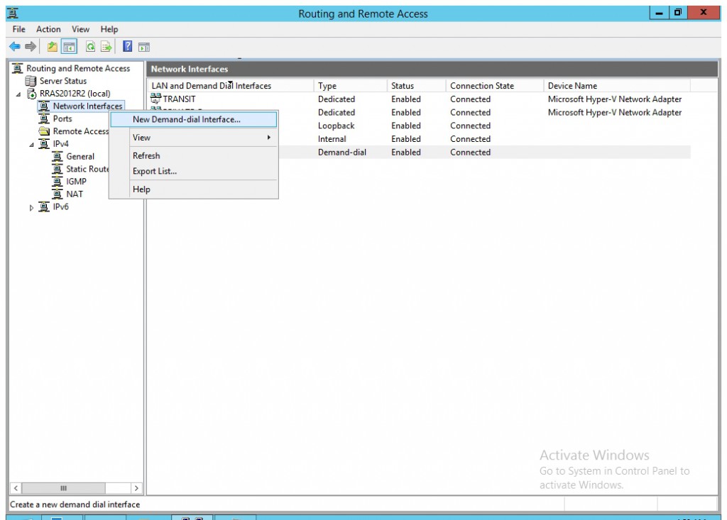
- Open Routing and Remote Access console.
- Right click "Network Interface" and select "New Demand-dial Interface".
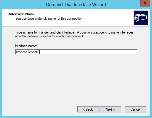
- Type a name and click "Next".
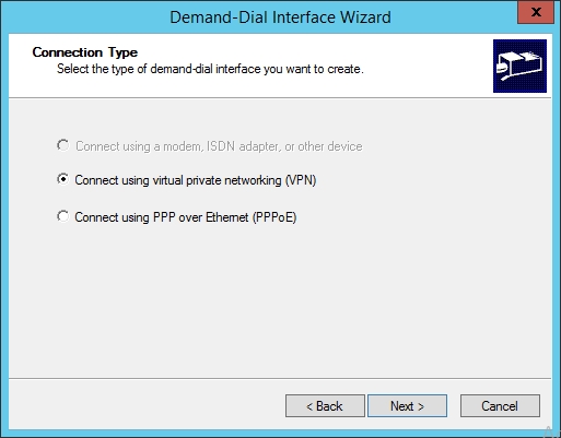
- Select "Connect using virtual private network (VPN)". Then click "Next".
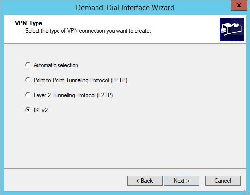
- Select "IKEv2", click "Next".
- Type the VIP of the gateway service. In my case, it's 10.10.10.99.
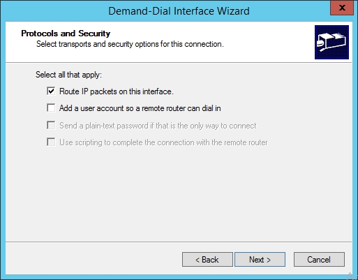
- Select the checkbox "Route IP packets on this interface". Then click "Next".
- Add the subnets of the VM network you want to connect to. In my case it's "12.0.0.0/24". Then click "Next".
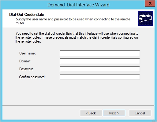
- Accept the default setting on the "Dial-Out Credentials" page and click "Next".
- Click "Finish".

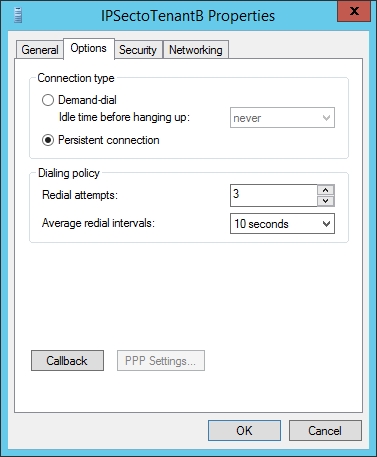
- Open the properties dialog window of the new created VPN interface. On the Option tab select Connection Type "Persistent connection". Optional you may also modify the dialing policy.
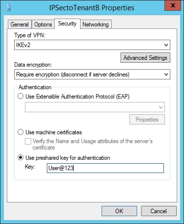
- On the Security tab, select "Use Pre-Shared key for authentication and key in the password. Then click "OK".
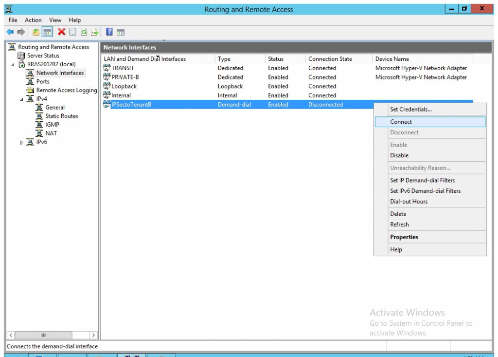
- Right click the new created VPN interface and select "Connect".
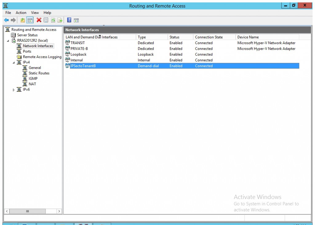
- Now you will see the interface connected.
- You may login the TESTVMIPSEC (12.0.0.4) and check if you could ping enterprise gateway (12.1.1.254) and the VM in the remote network (12.1.1.4).

Test Case 5: To validate S2S GRE connections
A S2S GRE connection allows you to access remote virtual machines and services from your datacenter. Use the following steps to configure a S2S GRE connection. In my case, I had already create a VM network called "VNET-GRE" (11.0.0.0/24) and create a VM "TESTVMGRE" (11.0.0.4)) in that VM network.
- Select the VM Network where you want to configure a S2S GRE connection and click Connectivity.
- Select Connect to another network through a VPN tunnel. You may also enable the outbound NAT for the VM Network if you want the VMs in that VM Network to be able to access external network. And select your Network Controller Service for the Gateway Device.

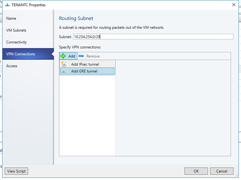
- Select the VPN Connections tab. Click Add and then select GRE type connection. Type a subnet as shown in the following diagram. This subnet is used to route packets out of the VM Network. This subnet does not need to be preconfigured in your datacenter.
- Give the connection a name. The name used in the example screenshot is GRE.
- Type the IP address of the Remote endpoint. In my setup, it's 192.168.30.3, which is the external IP of the remote GRE gateway.
- Type the GRE key.

- Select the Routes tab.
- Type all the remote subnets that you need to connect to.

Next we will configure the Enterprise Gateway.
Windows Server 2012 R2 can also support GRE tunneling by install the hofix KB3022776. The hotfix is not public available. You need to open a case to CTS and request the hotfix https://support.microsoft.com/en-us/kb/3022776 .
After install the above hotfix and reboot, please follow the steps below.
Same as the IPsec Gateway, you could not find the external IP from VMM Console in VMM TP5.
You have to access https://<NC Management IP>/Networking/v1/VirtualGateways and download JSON file. Then you may find the sourceIPAddress from the JSON file. That's the external IP of the gateway. In my case, it's 30.30.30.51.

Open PowerShell window and run the cmdlet below.
Add-VpnS2SInterface -Name GREtoTenant -Destination 30.30.30.51 -IPv4Subnet "11.0.0.0/24:100" -GreTunnel -GreKey "1234" -SourceIpAddress: 192.168.30.3Run the cmdlet below to verify GRE interface connected and there is traffic on it.
Get-VpnS2SInterface -name GREtoTenantGet-VpnS2SInterface -Name GREtoTenant | Get-VpnS2SInterfaceStatisticsTo validate that your S2S GRE connectivity is configured properly, you may login the TESTVMGRE (11.0.0.4) and try to ping the remote GRE gateway's internal IP (11.1.1.254) and a VM in the remote network (11.1.1.1).

Test Case 6: To validate L3 routing between HNV VM network and VLAN based VM Network
With L3 Gateway, you may create the direct connection between a HNV VM Network and a VLAN based VM Network. We don't support following scenarios.
- Multiple HNV VM networks connect to the same VLAN based VM Network
- HNV VM networks connect to the logical network's VM Network directly
Before to validate the L3 gateway, you need to first create a NC managed VLAN based VM Network. Here are the detailed steps.
- Right click "Logical Network" and select "Create Logical Network".
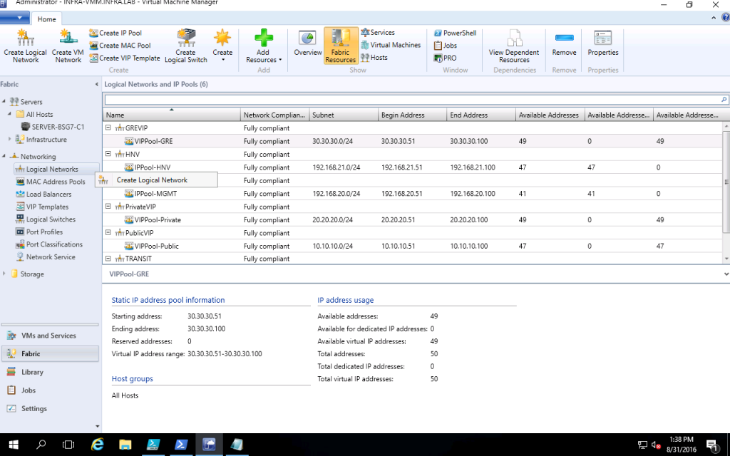
- Give it a name. In my case, I use the name "TENANT101".
- Select the check box "Create a VM network with the same name to allow virtual machines to access this logical network directly" and "Managed by Microsoft Network Controller". Please be informed it's different from the traditional VLAN based VM Network.

- On the "Network Site" tab, select "All Hosts" and input the corresponding VLAN ID and subnet. In my case, VLAN ID is 101 and Subnet is "192.168.11/24". Accept other default values.

- On the Summary tab click "Finish".
- Create a IP Pool under the above new created logical network. Give it a name and accept the default value on the "Network Site" tab.

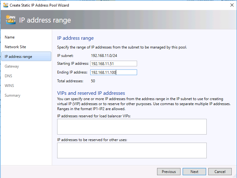
- Configure the Starting IP address and Ending IP address of the IP Pool. In my case, it's 192.168.11.51 and 192.168.11.100.
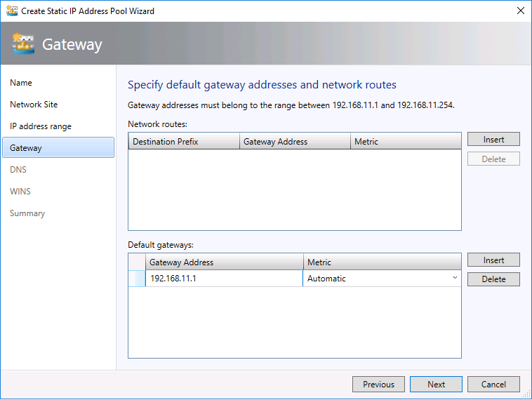
- Insert the default gateway
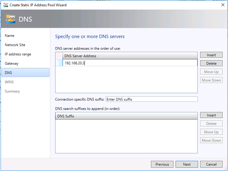
- Insert the DNS server.
- You may skip the WINS configuration and click Finish on Summary tab.
- Then you may create VM (in my setup , it's TENANT-L3-VM101) in the above new created VM Network.
To configure an L3 connection, use the following sample PowerShell script. You must run this as an administrator on the VMM server:
 param(
[Parameter(Mandatory=$true)]
# Name of the L3 VPN connection
$L3VPNConnectionName,
[Parameter(Mandatory=$true)]
# Name of the VM network to create gateway
$VmNetworkName,
[Parameter(Mandatory=$true)]
# Name of the Next Hop one connected VM network
# used for forwarding
$NextHopVmNetworkName,
[Parameter(Mandatory=$true)]
# IPAddresses on the local side that will be used
# for forwarding
# Format should be @("10.10.10.100/24")
$LocalIPAddresses,
[Parameter(Mandatory=$true)]
# IPAddresses on the remote side that will be used
# for forwarding
# Format should be @("10.10.10.200")
$PeerIPAddresses,
[Parameter(Mandatory=$false)]
# Subnet for the L3 gateway
# default value 10.254.254.0/29
$GatewaySubnet = "10.254.254.0/29",
[Parameter(Mandatory=$false)]
# List of subnets for remote tenants to add routes for static routing
# Format should be @("14.1.20.0/24","14.1.20.0/24");
$RoutingSubnets = @()
)

Import-Module virtualmachinemanager

$vmNetwork = Get-SCVMNetwork -Name $VmNetworkName;

$nextHopVmNetwork = Get-SCVMNetwork -Name $NextHopVmNetworkName;

$gatewayDevice = Get-SCNetworkGateway | Where {$_.Model -Match "Microsoft Network Controller"};

$vmNetworkGatewayName = $VmNetwork.Name + "_Gateway";
$VmNetworkGateway = Add-SCVMNetworkGateway -Name $vmNetworkGatewayName -EnableBGP $false -NetworkGateway $gatewayDevice
    -VMNetwork $vmNetwork -RoutingIPSubnet $GatewaySubnet;

$vpnConnection = Add-SCVPNConnection  -NextHopNetwork $nexthopvmNetwork  -Name $L3VPNConnectionName
    -IPAddresses $LocalIPAddresses -PeerIPAddresses $PeerIPAddresses -VMNetworkGateway $VmNetworkGateway -protocol L3;
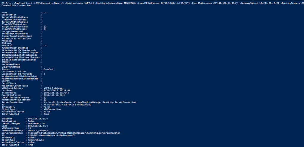
Write-Output "Created VPN Connection " $vpnConnection;

foreach($route in $RoutingSubnets)
{
    Add-SCNetworkRoute -IPSubnet $route -RunAsynchronously -VPNConnection $vpnConnection
        -VMNetworkGateway $VmNetworkGateway
}
Here is an example:
.\Config-L3.ps1 -L3VPNConnectionName L3 -VmNetworkName VNET-L3 -NextHopVmNetworkName TENANT101 -LocalIPAddresses @("192.168.11.253/24") -PeerIPAddresses @("192.168.11.254") -GatewaySubnet 10.254.254.0/29 -RoutingSubnets @("192.168.11.0/24")
Please be informed that both LocalIPAddresses and PeerIPAddresses are the available addresses in the VLAN based VM Nework.
Now you may login the VM in the VLAN based VM Network(In my setup, it's TENANT-L3-VM101) and add the following static route
route ADD 13.0.0.0 MASK 255.255.255.0 192.168.11.253 METRIC 3 -p
If you don't want to configure the static route, you may also change the default gateway of the above VM to 192.168.11.253.
Last you may test the PING between the two VMs in the VNET-L3 and TENANT101.

Kudo to SDN & VMM team
At end of this blog, I want to show my appreciation to SDN & VMM team who help me a lot during my test, also my teammate Brent Scallan.
- Manish Jha
- Ramandeep Singh Dhillon
- Subba Raju Thikkireddy
- Pradeep Reddy
- Sanjay Pavan Chaluvadi
Comments
- Anonymous
June 01, 2016
Thank you SDN-VMM TEAM for these Awesome blogpost series !
