DirectX: DrawIndexedInstanced and the Concepts behind a Home-Made Game Engine
Introduction
This article describes an intuitive implementation plan of what is known as "Instancing Drawing". To elaborate, DirectX has a class called "DeviceContext", and this class has a method called "DrawIndexedInstanced" which we can use as the cornerstone for a proprietary game engine. The challenge is that this method is not easy to implement, as there are several concepts that need to be understood in order to use it properly. What I'm trying to do with this document is to provide a practical explanation in plain terms about what happens within a typical game engine, focusing on how it leads towards the use of the "DrawIndexedInstanced" method.
Notes about this article:
- In order to be able to provide a clear description, some concepts are overly simplified. The objective is to explain, clear and simple, what happens in practical terms.
- There is not going to be any coding here, for the exception of a few statements that will be shown for presentation purposes. Beside, my code is so bad that it's best to look at the work of other, more experienced programmers.
- We are going to focus on 2D games because they are easier to understand. However, the same concepts apply for 3D games (there's a section for that here).
- The concepts are described the way I implemented them for my own engine. Some of them sound a little bit "out-there", but that is the way I was able to make them work.
- The objective is not to promote the creation of custom game engines. In fact, I'm hoping that Indies that are already using a commercial game engine can find some value in this article by understanding what happens "under the hood", allowing them to use their game engine of choice in a more efficient way.
The Hardware
In order to define what the core of a game engine does, we need to understand the most important problem it solves. To do so, we need to chat about computer hardware.
We'll start by stating that a video adapter is pretty much a computer by itself: It has a processor called "Graphic Processor Unit" (or GPU for short) and a memory bank (sometimes referred as "VRAM"). Just like any computer, it has a program to execute called "shader", and a block of data to process.
The difference, though, is that the GPU main task is to create triangles. Ok, granted, this is an overly simplified description of a powerful resource. However, for the purpose of this article, a video adapter is nothing but a "monkey" whose only concern is to paint triangles on the screen.
To elaborate, every time a game wants to show an image on the screen, it sends to the GPU four coordinates that it will use to create two adjacent triangles. The game also sends a digital copy of the image that the GPU will use as the filler of the triangles it just created. These coordinates are called "vertices" (plural for "vertex"), these triangles are called "faces", and the digital copy of the image is called "texture".
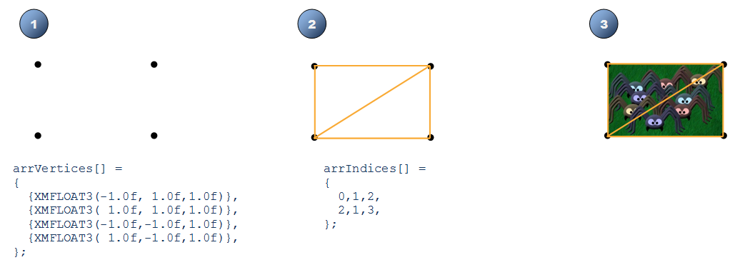
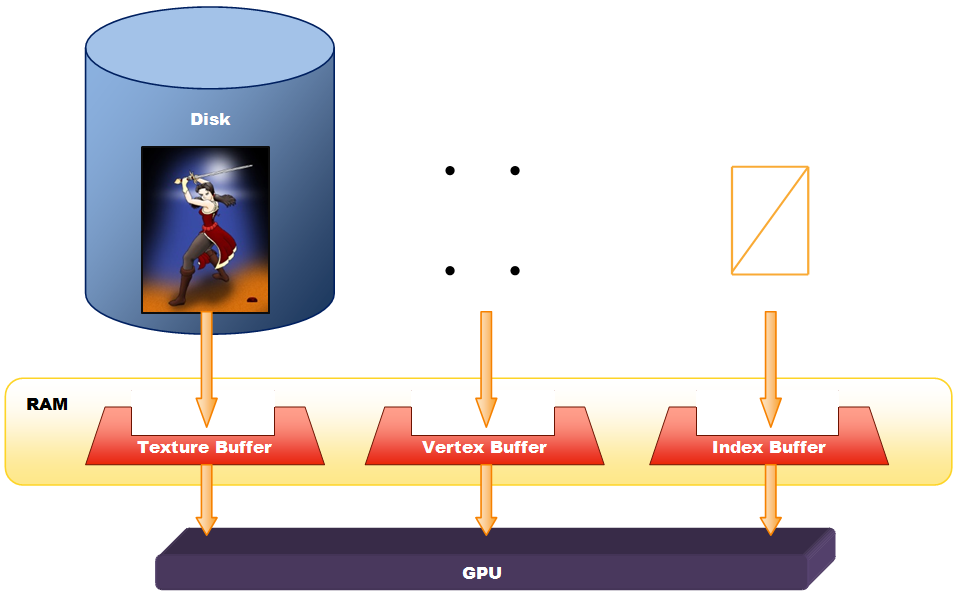
Now, the game has all these digital images or "textures" stored in RAM, packed in a specific format called "Buffer". Likewise, the four coordinates or "vertices" are also stored in a "Buffer", and our two adjacent triangles are also stored in yet another "Buffer". When our game wants to draw our image, it sends these buffers to the GPU. To recap:
- Vertex Buffer: This buffer has four coordinates on the screen.
- Index Buffer: This buffer has two adjacent triangles created by using the coordinates in the Vertex Buffer. It is called "Index Buffer" because each triangle is actually three numbers, and each number is an "index" to a vertex in the Vertex Buffer.
- Texture Buffer: This buffer has the digital image to use as the filler for the triangles that will be drawn.
The Problem
The main problem that this architecture presents is that, although the Vertex Buffer and the Index Buffer are pretty small, the Texture Buffer is rather big. It doesn't matter if the size of the image file in the Hard Drive is small, anything that is loaded into a buffer has to be uncompressed, and that makes pretty much every image (even a 1kb PNG) a texture buffer in the order of megabytes. For five or six images to draw, this is fine. However, when the number of images to draw is in the order of thousands (for example, a 30 x 40 tile map for a top-down shooter), the amount of data to send on every frame (that would be about 60 times per second) is huge. It doesn't matter the amount of cores the CPU has or the number of "threads" we have running, or even the clock speed the manufacturer says it runs, when the entire data bus of a typical user's PC motherboard is busy copying memory blocks, no data or code can be loaded (let alone processed) by the CPU, which in layman's terms means that pretty much everything is frozen until the darn texture buffer is copied entirely from the RAM to the video card. That said, it is easy to understand why this becomes a bottleneck.
The Solution
The obvious solution is to optimize the transfer of information from our game to the video adapter.
The Starting Point
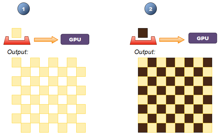
Let's take the example of a chess board, where we have only two basic textures to worry about: mahogany and beige. Ok, my bad, let's stick to black and white. The easiest way to show this board on the screen is to have a nested loop to draw 64 squares starting from the top left all the way 8 units to the right, and then repeat for each row. An inefficient "draw" routine would send a texture buffer on every call. If each image is loaded in a 1 megabyte texture buffer, the game will be sending the equivalent of the contents of the PC's hard disk drive by the time the player finishes his chess match.
Now, a way to optimize this example is to first focus on the white cells by creating a nested loop that will start from the top left corner all the way 8 units to the right and then repeat for each row, drawing a texture on every other cell. Then, focus on the black cells by creating a second nested loop that will start from the top left corner all the way 8 units to the right and then repeat for each row, drawing a texture on every other cell but skipping the very first one. In this case, a more efficient "draw" routine would send the white cell texture buffer on the first call, and then on the next 31 calls would only send the "new" position where to re-paint said texture on the screen. I mean, the texture buffer is already in the VRAM, so we might just as well re-use it. Likewise, following the pseudo code previously described, on the second nested loop, it would send the black cell texture buffer and then, on the next 31 calls, it would only send the "new" position where to re-paint said texture on the screen, re-using the texture buffer that it has stored on its VRAM already.
Although this is a great optimization, it leaves the game developer with an utterly painful algorithm to implement. I mean, games are already complex enough to also expect the developer to draw it efficiently.
Batch Drawing
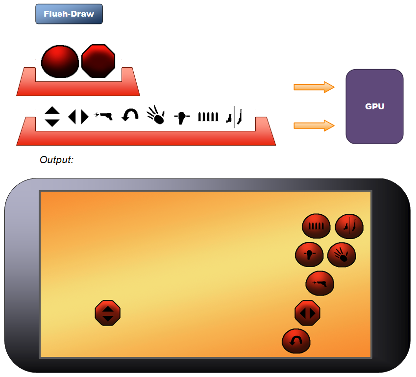
The solution for this problem can be described in layman's terms as follows: Instead of having one mere "Draw" routine, we have two: a "Pre-Draw" routine and a "Flush-Draw" routine.
Ok, I made those names up, but they are quite self explanatory so they fit the purpose of this article. After all, these two are supposed to be functions within our game engine.
Following the previous example, let's assume that we have just one nested loop to "pre-draw" all 64 cells of our chess board, starting from the top left corner all the way 8 units to the right, and then repeat for each row. This "Pre-Draw" routine would only take note of the texture that we want to show as well as the position where to show it on the screen, and yet it would send absolutely nothing to the video adapter. It would be like a waiter taking a customer's order in a fancy restaurant. At the end, the game would call the "flush-draw" routine, and, following our analogy, this is when the waiter leaves the table and enters into the kitchen. Here is where a nested loop starts: Following the notes taken by the "Pre-Draw" routine, for every image that was mentioned the "Flush-Draw" routine will send the texture buffer, instructing the video adapter's GPU to paint it for every requested position. The end result is that, no matter how inefficiently the game calls the Pre-Draw routine, the Flush-Draw routine will always make sure that texture buffers are sent only once, sending only the new position thereafter for every time the game requested to paint said texture. This optimization approach is known as "Batch Drawing".
(See diagram at the end of this section to get a good idea about the flow of information).
Based on this pseudo-code that was just described, the game's main loop doesn't really need to have any texture handy. Instead, only a "reference" to it is needed. After all, the game's main loop just needs to indicate, with said reference, which textures it wants to show on the screen, and everything will be taken care of when the "flush-draw" routine is called. Object-Oriented Programmers automatically take this fact as an invitation to encapsulate these texture handling operations in a single "texture manager" class. Getting a little bit obsessed with this new approach, we could just add loading methods to it to completely disassociate the game's main loop with anything that has to do with actual texture buffers, or even any type of buffer at all. Before we know it, this "Texture Manager" class becomes a home-made game engine. Quite primitive, and not fancy at all, but still, it takes the heavy load of dealing with memory buffers, image files and all communication with the video adapter, and its functionality is so defined and yet generic that we can re-use this implementation in further games.
There are some additional concepts that need to be mentioned here. Let's start by saying that a vertex is a coordinate which just happens to be a structure of numbers. Likewise, the triangles to draw are also three integers, and even the color acquired by sampling the texture to paint for a given pixel is also a structure of numbers (four, actually, representing the value of Red, Green, Blue and Alpha – this last one has to do with transparency). As numbers, we can manipulate them at our will. But to do so, it is best to do it at the video card adapter. Here is how: A shader is a program that it is executed by the GPU. In particular, a "vertex shader" is a program executed for every vertex to process. As we mention before, during our "flush-draw" routine, we send the texture to the video card once, and then we send the new coordinates for every time the game wants to show said texture on the screen. It is this "vertex shader" that receives the new coordinates, and "transforms" our original four vertices to the new position, successfully re-painting our image on the screen. Of course, we send the new position to the video card in the form of a memory buffer. In this case, it is called "input vertex shader buffer". The name makes sense: This is, after all, the input parameters that the vertex shader will use to relocate and paint our image on the screen.
Of all possible formats, the best way to send the new position of our texture is in a 4 by 4 Matrix. A Matrix is a Mathematical structure and, like any other structure of numbers, it has its own set of math operations. The awesome feature that applies here is that there is a math operation in which we can multiply a coordinate by a Matrix, and the end result is a coordinate with the "changes" defined within the Matrix itself. Now, there are three basic changes that are of great interest when it comes to batch drawing:
- Translation, so we can show our texture in any position on the screen,
- Scale (both in "X" and "Y", which are pretty much independent from each other), so we can resize our texture as we need it,
- Rotation, with is the basic effect in a typical top-down shooter.
Now, getting a little bit obsessed about this, a "pixel shader" is a program that is executed by the GPU for every pixel to paint on the screen. Long story short, this is the little one that takes a "sample" of the texture that we want to show on the screen, it deduces the color to use, and sends the information to the "pixel" at the screen. All these pixels altogether will become our pair of adjacent triangles, showing the image on the screen.
Like any shader, a Pixel Shader can have a set of input parameters that will affect the color of the pixel to show. That is, by specifying certain parameter, we can make our image shown darker, brighter, semi-transparent, reddish, negative, and a whole list of other effects that we can create by playing with the numbers that represent the sampled color from the original texture.
There's a great interest on creating sophisticated shaders to implement impressive visual effects. However, the part that this article is interested is in the optimization of information flow towards the GPU. Following the example of a chess board in a batch drawing process, the "flush-draw" routine could simply send the texture for the "white" cell, and then use a vertex shader and a pixel shader to paint this same image 64 times on the screen, specifying a position and a color (black or white) each time.

Before proceeding, let's recap the new elements for the engine:
- Vertex Shader: This is the program that the GPU executes for every vertex to process. This shader can do a lot of great things, however, for the purpose of this article, its job is to relocate these vertices on the screen. These vertices are moved according to where we want our image, how big we want it shown and even if we want it rotated.
- Pixel Shader: This is the program that the GPU executes for every pixel on the screen. This shader can do a lot of great things, however, for the purpose of this article, its job is to get a "sample" from the texture to show and deduce the color for the pixel on the screen. Part of its job description is to be able to "alter" this color. As of DirectX11, pixel and vertex shaders are loaded separately.
- Input Vertex Shader Buffer: This is the input data for the Vertex Shader. This is usually a 4 by 4 Matrix with size, translation and rotation information. In a batch drawing approach, this buffer is sent once for every time we want to show a texture on a particular position on the screen.
- Input Pixel Shader Buffer: This is the input data for the Pixel Shader. This is usually a "vector" made of four floats, representing constants to multiply the sampled color of a texture. For example, a value of (1, 1, 1, 1) - associated as red, green, blue and alpha respectively - will leave the texture as it is, (1, 1, 1, 0.5) will make the texture semi-transparent, (0.5, 0.5, 0.5, 1) will make the image dark, etc.
Texture Atlas
To understand the next optimization step, let's follow the example of the tile map of a top-down shooter. Using batch drawing, the amount of information is optimized so a texture is sent only once, and then painted in multiple positions. A typical scenario would be that we only send about 20 different textures for the thousands of tiles that the game needs to show in a single frame for the 30 x 40 tile map.
Now, let's start optimizing this scenario: By definition, the tiles of a map are of the same size. Let's assume now that we put together in a single texture all the different tiles that we could ever use to draw a map of a given game level. Following this example, it would be a unit tall times 20 units wide. In that way, when the game wants to draw a map on the screen, it would send this single texture, and then indicate in the Vertex Shader Input not only the new position, but also which "section" of our big texture we want to show. This optimization approach is known as using a "texture atlas".
I find this technique quite straight forward to implement when all images to show are of the same height, like the tiled map we have described. In that way, when all tiles are together in a single line, we only need to worry about the horizontal position within the texture atlas. That keeps things easy to handle, even if not all the tiles are of the same width. The truth is that this technique can be used so a texture atlas can include tiles both vertically and horizontally, and they don't even have to be of the same dimensions, but this is a scenario way, way too complex to implement.
Texture Atlas has a major problem, though: When showing a particular tile of a texture atlas, if the image's pixels to show don't exactly match the screen pixels to use, the pixel shader will try to stretch or shrink the image in order to best match the geometry of the pixels on the screen. This causes the colors of the adjacent textures of our atlas to show. This problem is known as "image bleeding". To solve this problem, the texture atlas should have a gap in both sides (and maybe in all four sides, depending on how the texture atlas is built), so the texture sampling does not affect the image we want to show.
The image bleeding side effect, along with the intrinsic complexity, may suggest that a texture atlas may generate more problems than solve them. Still, it is a great approach for images with a transparent background. A good example, aside animation sheets, is the use of bitmap fonts where the whole alphabet is in a single texture. In that way, a game engine can use a texture atlas, one entry for each letter, using it to show an entire paragraph on the screen, sending one single big texture to the video card instead of sending small textures for every letter.
The reason why Texture Atlas is so useful is because the time it takes to transfer information to the video adapter is seldom "linear", meaning that sending individual texture buffers to the VRAM is slower than sending one single buffer with all textures to use combined. The cause of this discrepancy depends on a case-by-case scenario, but it is my experience that some GPUs don't appreciate being interrupted so the transfer of data between RAM and VRAM can take place.
Instancing
Let's follow the example of a paragraph shown on the screen using a bitmap font. Although a Texture Atlas would send the entire alphabet to the video adapter in one single texture buffer, the "Flush-Draw" routine still needs to send position information for every letter to show for said paragraph. Considering that a paragraph has usually around half a thousand letters, the GPU gets called quite a lot for every frame to show on the screen.
Now, here is the opportunity for improvement: the "Flush-Draw" routine already knows all positions where a given texture (or a part of a texture if we're using an atlas) needs to be shown on the screen. That said, instead of sending each position embedded in a buffer one at a time, it can send all positions to process all of them embedded in one single buffer. This technique is known as "Instance Drawing", or simply "Instancing". Following the example of a paragraph shown on the screen using a bitmap font, the "Flush-Draw" routine would send the alphabet in a single texture buffer, and then it would send a second buffer with all the position of all the letters to be shown on the screen.
The best part is that new GPUs have been designed to handle instance drawing "natively". The approach is a little bit "abstract" so it is somewhat hard to understand: A Vertex Buffer is made of an array of a data structure representing a vertex, and this document has simplified this concept by stating that said vertex is just a coordinate on the screen. Therefore, we can deduce that the data structure that represents one vertex is just a vector made of three floats representing the position on the screen (a 2D game would use only "x" and "y", whereas a 3D game would use all three axis). However, the data structure representing a vertex is not "fixed". In fact, we can define this data structure as we see fit. For example, 3D Modelers have taken advantage of this fact by associated a vertex with a coordinate in space, a coordinate within a texture, a unit vector representing a normal, a color, another coordinate within a texture, not one nor two but four skin weights, and so many more possible combinations based on the visual effects that they want to achieve. There are some rules to follow, but still, as long as the Vertex Shader knows what he's receiving, there is a lot of freedom in regards of the information that we can associate with a vertex.
Taking the advantage of the fact that we can define a data structure as we see fit, we can use a secondary Vertex Buffer and define our new data structure with the new position of the texture to paint on the screen. In other words, when using Instance Drawing, the "Flush-Draw" routine uses two vertex buffers:
- The first vertex buffer has an array of four standard coordinates, just like we have described throughout this document. Assuming (x, y z), these would be: (-1, 1, 1), (1, 1, 1), (-1, -1, 1) and (1, -1, 1)
- Although we are assuming a 2D game, it is good practice to define the "z" axis in these standard coordinates. In that way, our code would work just as well for a 3D game. Following this line of thought, "z" is equal to "1" just to keep it standard.
- Depending on how the "device" adapter is modeled, usually the center of the screen is at coordinate (0, 0, 1).
- The use of "1" is so we can use math to "transform" these coordinates to the final position on the screen where the game wants to show a give image. Think of it as "percentages". In that way, the size of the screen is no longer a definitive factor, to the point that the game will look the same no matter if the screen size is different from one PC to the next one.
- That said, the data structure for one entry would be a vector with three floats.
- The second vertex buffer has an array representing the number of times we need to paint a given image on the screen.
- Under this context, the data structure should include the input data for the Vertex Shader, which includes the new position, size and rotation of the image to show on the screen (as described in batch drawing).
- The data structure should also include the input data for the Pixel Shader, which includes the new color (if we want to "tint" the image) and the coordinates within the texture (if we are using texture atlas features).
- Although we can define our data structure the way we need it, there are two restriction to comply:
- We can only use variable types compatible with the shader language to use, in this case, Hi-Level Shader Language, or HLSL. I mean, if the shader cannot understand it then there's no point on sending it.
- The size of the data structure, in bytes, should be a multiple of 16. This is a compiler restriction.
- These restrictions impose a big challenge: There is no "Matrix" data structure. This is a little bit of a shocker, as the "Batch Drawing" process described earlier recommends the use of a 4 by 4 Matrix to send all information related to position, size and rotation perfectly packed and ready to use.
- No mater, though, for we can split a 4x4 Matrix in four vectors of 4 floats each, which is consistent with the allowed data types to use for our "custom" data structure. The downside is that we would need to have code to receive these four vectors and assemble our 4 by 4 matrix so we can use it to transform the four vertices from the first Vertex Buffer.
There are some challenges that need to be mentioned when implementing instancing, starting with the fact that memory buffers are rather "static" structures. That is, a buffer cannot "grow" or "shrink" if needed, and we cannot destroy and create new buffers on every draw call. I mean, we could do it, but allocating and de-allocating memory are expensive operation that would drop the game's overall performance to a halt. On the other hand, we cannot have a buffer of, say, a thousand entries (that would work great with our paragraph example) for drawing a single image on the screen, for example the background sky.
The solution I found for this problem was to have multiple buffers with different amount of entries, to be used according to the number of copies of a given texture to show on the screen. For example, we could have one small buffer with just a few entries to be used when we want to show one single copy (for example the background sky), we could have one medium buffer with about a hundred entries to be used when we want to show multiple copies of a single texture (like the chess board described in earlier examples), and we could have one big buffer with a huge amount of entries to be used when we want to show text (like the paragraph described in earlier examples), or even a particle effect (like snow). I use six buffers of the following sizes: 1, 4, 16, 64, 256 and 800.
There are many more concepts related to the creation of a game engine, but pretty much the ones described in this document are the bare essentials.
DrawIndexedInstanced Method
Although the objective of this article was about concepts without incurring into code, I have to admit that the information described here would be pointless unless there is a small glimpse of what really happens "under the hood". For this section of the document, let's focus on Visual C++ using DirectX 11 for a Universal Windows Platform videogame. There are many, many key statements involved on the algorithms described in this article. However, the ones that drive the whole engine, conveniently coded in our "Flush-Draw" routine, can be listed as follows:
// ***** Set the Vertex Shader... ****** //
d3dContext->VSSetShader(shrSpriteBatchVxInstance.Get(), nullptr, 0);
- The object "d3dContext" is actually an instance of DirectX's ID3D11DeviceContext or any of its inherited offspring (ID3D11DeviceContext1, ID3D11DeviceContext2 ... )
- In layman's terms, and just for the scope of this article, a "DirectX Device Context" is the main object that is in charge of sending information to a video adapter.
- The method "VSSetShader" sets the Vertex Shader to use, in this case represented by "shrSpriteBatchVxInstance".
- We don't need to set the shader every time the Flush-Draw routine is called. What I recommend is to keep tabs of which is the current vertex shader in use, and only set it up when it needs to be changed. To err on caution, assume that the shader is not persistent between frames, so best case scenario the Vertex Shader needs to be set at least once every frame.
// ***** Set the Pixel Shader... ****** //
d3dContext->PSSetShader(shrSpriteBatchPxInstance.Get(), nullptr, 0);
- Likewise, the method "PSSetShader" sets the Pixel Shader to use, in this case represented by "shrSpriteBatchPxInstance".
- We don't need to set the shader every time the Flush-Draw routine is called. What I recommend is to keep tabs of which is the current pixel shader in use, and only set it up when it needs to be changed. To err on caution, assume that the shader is not persistent between frames, so best case scenario the Pixel Shader needs to be set at least once every frame
// ***** Staging the Face Buffer in the Input Assembly... ***** //
d3dContext->IASetIndexBuffer(bfrIndexBuffer.Get(), DXGI_FORMAT_R16_UINT, 0);
- The method "IASetIndexBuffer" sends our Index Buffer, represented by "bfrIndexBuffer", to the video adapter. In other words, it sets our two adjacent triangles to show on the screen, each one represented by three small integers (hence the constant DXGI_FORMAT_R16_UINT) pointing to three vertices defining the triangle to draw.
- So far, this has been straight forward.
// ***** Staging the Vertex Buffer in the Input Assembly... ***** //
d3dContext->IASetVertexBuffers(0, 2, arrVertexBuffers, arrSpriteStrides, arrSpriteOffsets);
- The method "IASetVertexBuffers" sets the Vertex Buffers (note the "s") to use. Here is where things get cryptic.
- As mentioned before in the "Instancing" section, we need two Vertex Buffers:
- The first Vertex Buffer has the array of our four standard coordinates needed to paint our two triangles on the screen.
- The second Vertex Buffer has the array representing the number of times we need to paint a given image on the screen.
- In this case, "arrVertexBuffers" represents the array that contains these two Vertex Buffers.
- The "2" explicitly defines that we are using two Vertex Buffers. C++ is like that: If you're sending an array, you need to specify how many elements are on said array.
- In this case, the array "arrSpriteStrides" is an array of two entries, and each entry is the size of an individual record on each Vertex Buffer. In layman's terms, a buffer is a bunch of bytes, and it is up to the Vertex Shader to figure out what they mean. However, since it is going to be executed for every entry, the GPU needs to at least know the size of each entry so it can send the right chunk of bytes from the buffer to the Shader, and execute the Vertex Shader one entry at a time. Using the chessboard example from before, the GPU needs to know for each square where the information starts and where it ends, so it can run the Vertex Shader one square at a time (actually, it runs four times as we have four coordinates on our first Vertex Buffer, times 64 as that is the number of squares we have on our chessboard).
- Ignore the last variable "arrSpriteOffsets". This one is just an array of two zeros, as follows: {0, 0};
// ***** The Faces are drawn... ***** //
d3dContext->DrawIndexedInstanced(lngFaceCountTimes3, lngCount, 0, 0, 0);
- The method "DrawIndexedInstanced" triggers the entire "indexing" process on the video card side.
- In this case, "lngFaceCountTimes3" is the number of indexes on our Index Buffer, which is 6 (three for each triangle).
- Also, "lngCount" is the number of times the image will be painted on the screen, (another way to define it is the number of instances of the texture to draw). Following the example of our chessboard, this will be 64.
The Difference between 2D and 3D
A 3D Model is the tri-dimensional, digital representation of an actual object. This representation is done using an array of vertices and adjacent triangles defined by said vertices. The model of a cube, for example, has 8 vertices and 12 adjacent triangles. The Model usually includes an image (or at least makes a reference to an image file). In this particular scenario, the image is often referred as "skin". When a 3D Model is loaded into memory, a videogame engine automatically creates a Vertex Buffer for the vertices, an Index Buffer for the triangles and a Texture Buffer for the skin. To paint a 3D Model on the screen, the game engine sends these three buffers and asks the GPU to render it, pretty much like this entire document has described for the case of two-dimensional images.
That said, we can conclude that, in practical terms, the difference between drawing 2D images and 3D models is:
- The Index buffer is loaded for each 3D Model, whereas when it comes to 2D images the Index Buffer is loaded only once,
- The "z" coordinate is now taken into consideration. This is done in combination with a "projection" matrix and a "view" matrix (both of them fall outside the scope of this document).
- Drawing 3D models often includes animation information... which is a topic to be addressed in a different article.
Other than that, pretty much everything is the same. Even Instancing applies, with or without animation information.
Conclusion
The information of this article has been focused on drawing images on the screen. We started by identifying the bottleneck in this process, and how to draw images in an efficient way by building a custom game engine as a result of the implementation of the DrawIndexedInstanced method.
The information provided is not enough to build one, though. There are many more details that need to be addressed, as well as new concepts to explore (no one can do all that in a single article). However, it has provided an overview of the implementation path to follow, as well as a clear description of the inside work of a typical game engine.