Azure VNet: Connect Hubs and Spokes using Site-to-site VPN
Introduction
In this article, we will cover a specific scenario related to Hub & Spoke network connectivity. This article assumes that you have a basic understanding of Azure Networking and related components.
Problem Statement
A global organization is planning for its cloud journey, and they have selected Microsoft Azure as their preferred cloud service provider.
- Being a global organization, they will deploy their services in multiple Azure regions. Each region will have its own regional hub, which will cater all infrastructure related services (Domain Controllers, DNS Servers, Firewalls) for that region.
- In addition, there will be spokes which will be used by business applications and services. **All spokes would be connected to the regional hub. **
- Also, all hubs and spokes need to be connected to on-premises Data Centers.
- Another important requirement is encryption in transit. All network communication must be encrypted to prevent any interception.
- The organization does not want to use BGP in Site-to-site VPN configuration.
Solution Overview
We have designed below solution to fulfill the above requirements :

**As traffic encryption is one of the primary requirement, we could not opt for VNet Peering. Traffic in VNet Peering flows through Microsoft backbone network, but it is not encrypted. **
- Since we could not use VNet Peering, we have two options 1) Site-to-site VPN and 2) VNet-to-VNet.
- Among these two options, we opted for Site-to-site VPN, since it offers more flexibility. We will discuss this in more detail later.
- All hubs and spokes are connected with each other through site-to-site VPN.
- The on-premises hub which you can see in the diagram is actually another Azure VNet. In the absence of a real on-premises location in our lab, this Azure VNet would represent the on-premises data center.
Step 1: Create a Resource Group
We have created a Resource Group TestNetworkDesign. We will create all network resources within this resource group.
Step 2: Create VNets
We have created below VNets :


Step 3: Create VPN Gateway
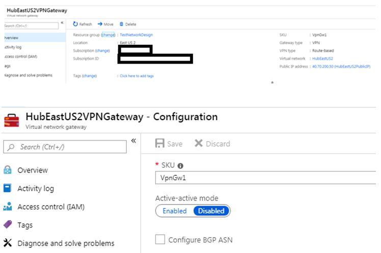
We have created VPN Gateway in each VNet, under the gateway subnet. These VPN Gateways would be used while configuring Site-to-site VPN connection.
- You can create only one VPN Gateway per VNet. Even if you want to create multiple S2S connections to connect your VNet with other VNets and on-premises, you have to use that single VPN Gateway within that VNet.
- The VPN gateway must be within Gateway Subnet. Please do not create any other resource under Gateway Subnet, and please do not try to rename that subnet.
- Select VPN Type as Route Based.
- BGP is not enabled.
- Azure VPN gateway comes with multiple SKUs, here we have selected VpnGw1.
- The VPN Gateway must have one Public IP, which Azure will automatically provide during creation. This Public IP address will not be changed unless you are deleting and re-creating the VPN gateway.
- By default, Active-Active mode is disabled. In general, this should be fine because by default Azure VPN gateway has a hot standby, and creates two service VMs per VPN gateway.
Step 4: Create Local Network Gateway
**Local Network Gateway represents the VPN Gateway of the opposite side. We can call it a local representation of the remote VPN Gateway, which is configured on the other side. **
So for each Site-to-site connection, we need a local network gateway, which will represent the opposite side VPN gateway.
For a site-to-site connection between A & B, this is how the connection is actually configured:
- From location A: VPN Gateway of A and Local Network gateway of B (created at location A)
- From location B: VPN Gateway of B and Local Network gateway of A (created at location B)
In Site-to-site connection, we have to create each Local Network gateway manually. However, in VNet-to-VNet connection, Azure will automatically configure the Local Network gateway. This is one key difference between S2S and VNet-to-vnet connection.
This is because, S2S connection can be created between heterogeneous environment, where one side is Azure and another side can be something else (Like on-premises). So the other site VPN Gateway may or may not be Azure VPN Gateway. On the other hand, VNet-to-VNet can be created only between Azure VNets, where all VPN gateway must be Azure VPN gateway.
However, due to this S2S offers more flexibility, as we are creating the local network gateway manually.
So in this case, we have to create the following Local VPN gateways :
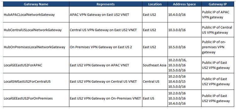
Notice the Address Space field carefully. The Address Space is a collection of one or more IP ranges, which represents the network which this Local Network Gateway represents.
For example, when we have created a local network gateway for East US2 in the APAC region, we have specified below address ranges :
- 10.2.0.0/16 (East US2)
- 10.3.0.0/16 (Central US)
- 10.5.0.0/16 (On-premises)
So this means, traffic between these above IP ranges and APAC VNet will use this local network gateway. If you check our network topology diagram, this point will become clear to you.
You can add/remove address ranges later based on your requirement.
If one VPN Gateway is connected to multiple VPN Gateway's through S2S, then for every connection a separate Local Network gateway is required to represent this network.
For example, in this case, EastUS2 VNet is connected to three different VNets through S2S, 1) APAC 2) central US 3) on-premises. So we have created three different Local Network Gateway's to represent this East US2 VPN Gateway. We cannot create a single Local Network gateway for East US2 and use it to represent multiple networks. If we do so, we will encounter address overlapping error while configuring address spaces.
So we have created local VPN gateways, which you can see in the below diagram.

Step 5: Create Site-to-site VPN connections
VPN Gateways and Local VPN Gateways are now ready. It's time to establish the connection.
Please note that Site-to-site VPN connection needs to be created from both ends.
For example, to establish a Site to site connectivity between HUB APAC VNet and HUB East US2 VNet, we need to create below two connections :
- S2S connection between APAC VNet VPN gateway and East US2 Local Network Gateway.
- S2S connection between East US2 VNet VPN gateway and APAC Local Network Gateway.
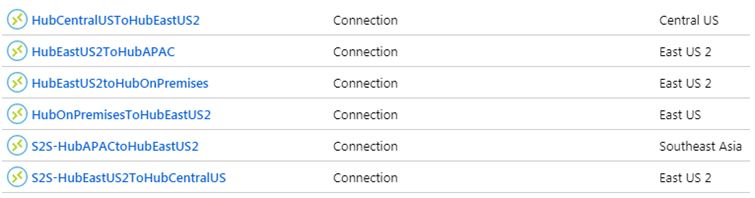
Likewise, we need two connections between each combination, and so there will be a total 6 connections as shown below.
To create connection, go to VPN Gateway and then go to connection section. From there, add a new connection, select the Local Network Gateway representing another side, and then proceed.
Also, use the same shared key on both sides, otherwise the connection will not be established successfully.
If the other side is on-premises, then you should incorporate the same shared key in the on-premises VPN Gateway device. So we have created below 6 connections.
Initially, the connection status would be randomly changed between Unknown, Successful and Connecting, but after approx 5 minutes the status should be Connected.
You should also see some data in and data out.

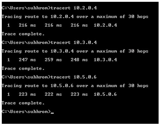
Step 6: Perform Hub Connectivity Tests
We have created one Azure VM in each Hub VNet so that we can perform connectivity tests using Ping and Tracert. Please note that those Azure VMs have been created in different subnets, not in Gateway subnets.

We are pinging other VNets from APAC Hub VM. As you can see in the below diagram, we are getting a ping response from VMs in all other VNets. Likewise, you can ping from other VMs.
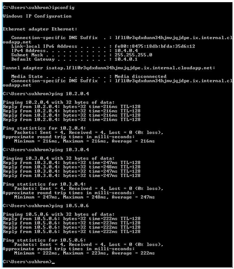
The Tracert output shows that there is no hop in between because the connections are using VPN gateways.
One important point to note here is that no UDR (User Defined Routes) have been configured to establish this connectivity. This is because we have used address spaces for each local network gateway so that traffic would know which gateway to use for which network destination.
For example, when traffic from APAC VNET would go for central US VNET, it will follow the below process :
- The destination network is 10.3.0.0/16, which is one hop away.
- However, as we have specified the address range 10.3.0.0/16 in the Local Network Gateway for East US2 which is configured for APAC, the traffic would utilize this gateway.
Create and Connect Spoke VNETs
Before we create Spoke VNets, it is strongly recommended to create an IP addressing plan for Spokes. I have published one sample table below.
Name |
Spoke CIDRs |
APAC Spokes |
10.7.0.0/22 |
East US2 Spokes |
10.8.0.0/22 |
Central US Spokes |
10.9.0.0/22 |
Now, let's assume we have to connect APAC Spoke1 VNet with APAC Hub VNet. The Spoke and Hub VNets can be in the same subscription or in different subscriptions.
The address range of APAC Spoke1: 10.7.0.0/22
The address range of APAC Hub: 10.4.0.0/16
Below are the high-level steps to establish the connection:
Create a VPN Gateway at APAC Spoke1 VNet. This will be created within Gateway Subnet.
Create a Local Network Gateway at APAC Spoke1 VNet. The Local Network Gateway will be created within Spoke VNet subscription, and it will represent APAC Hub VNet.
Address space for this local network gateway would be as follows :
10.4.0.0/16
10.2.0.0/16
10.3.0.0/16
10.5.0.0/16
3) Create a Local Network Gateway at APAC Hub VNet. The Local Network Gateway will be created within the Hub VNet subscription, and it will represent APAC Spoke VNet.
Address space for this local network gateway would be as follows :
10.7.0.0/22
- Now, establish connections from both sides :
- S2S connection between APAC Hub VPN gateway and APAC Spoke1 Local Network gateway.
- S2S connection between APAC Spoke1 VPN gateway and APAC Hub Local Network VPN gateway.
*With this, Hub & Spokes are connected.
*
However, in order to ensure that traffic from other Hubs and Spokes in other regions can reach this spoke, you need to publish the spoke CIDR range in each Local Gateway where it is relevant.
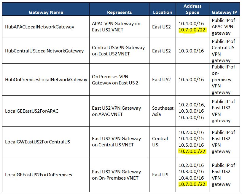
In our present topology, we need to add the address range in below Local Network Gateways :
- APAC Hub VNet Local Network Gateway for East US2 ( So that East US2 Hub can reach APAC Spoke1 VNet)
- East US2 Hub VNet Local Network gateway for Central US ( So that Central US Hub can reach APAC Spoke1 VNet)
- East US2 Hub VNet Local Network gateway for On-premises ( So that On-premises network can reach APAC Spoke1 VNet)
So our Local Network Gateway table now looks like this :
In addition, if there are additional spokes already connected to any of these hubs (including APAC Hub), then the Local Network Gateways which are created at these spokes for corresponding Hubs also need to be updated with the new address space.
As you can understand, with the growing number of Hubs and Spokes, the address space list would become longer and somehow difficult to manage.
**Also, each time you add a spoke, you need to publish that address range to relevant Local Network Gateways.
**
To combat this, the ideal solution is to use BGP (Border Gateway Protocol). Once BGP would be enabled on both side VPN Gateways, they will automatically exchange routing information. between VPN gateways.
To know more about BGP, please follow this link.
See Also
- Create a Site-to-Site connection in the Azure portal
- Step-By-Step: Configuring a site-to-site VPN Gateway between Azure and On-Premise
- Azure VPN Gateway
- Highly Available Cross-Premises and VNet-to-VNet Connectivity
- About policy-based and route-based VPN gateways
- Azure VPN Gateway FAQ
- About BGP with Azure VPN Gateway