Set up Pacemaker on Red Hat Enterprise Linux in Azure
This article describes how to configure a basic Pacemaker cluster on Red Hat Enterprise Server (RHEL). The instructions cover RHEL 7, RHEL 8, and RHEL 9.
Pre-requisites
Read the following SAP Notes and articles first:
RHEL High Availability (HA) documentation
- Configuring and managing high availability clusters.
- Support Policies for RHEL High-Availability Clusters - sbd and fence_sbd.
- Support Policies for RHEL High Availability clusters - fence_azure_arm.
- Software-Emulated Watchdog Known Limitations.
- Exploring RHEL High Availability's Components - sbd and fence_sbd.
- Design Guidance for RHEL High Availability Clusters - sbd Considerations.
- Considerations in adopting RHEL 8 - High Availability and Clusters
Azure-specific RHEL documentation
RHEL documentation for SAP offerings
- Support Policies for RHEL High Availability Clusters - Management of SAP S/4HANA in a cluster.
- Configuring SAP S/4HANA ASCS/ERS with Standalone Enqueue Server 2 (ENSA2) in Pacemaker.
- Configuring SAP HANA system replication in Pacemaker cluster.
- Red Hat Enterprise Linux HA Solution for SAP HANA Scale-Out and System Replication.
Overview
Important
Pacemaker clusters that span multiple Virtual networks(VNets)/subnets are not covered by standard support policies.
There are two options available on Azure for configuring the fencing in a pacemaker cluster for RHEL: Azure fence agent, which restarts a failed node via the Azure APIs, or you can use SBD device.
Important
In Azure, RHEL high availability cluster with storage based fencing (fence_sbd) uses software-emulated watchdog. It is important to review Software-Emulated Watchdog Known Limitations and Support Policies for RHEL High Availability Clusters - sbd and fence_sbd when selecting SBD as the fencing mechanism.
Use an SBD device
Note
The fencing mechanism with SBD is supported on RHEL 8.8 and higher, and RHEL 9.0 and higher.
You can configure the SBD device by using either of two options:
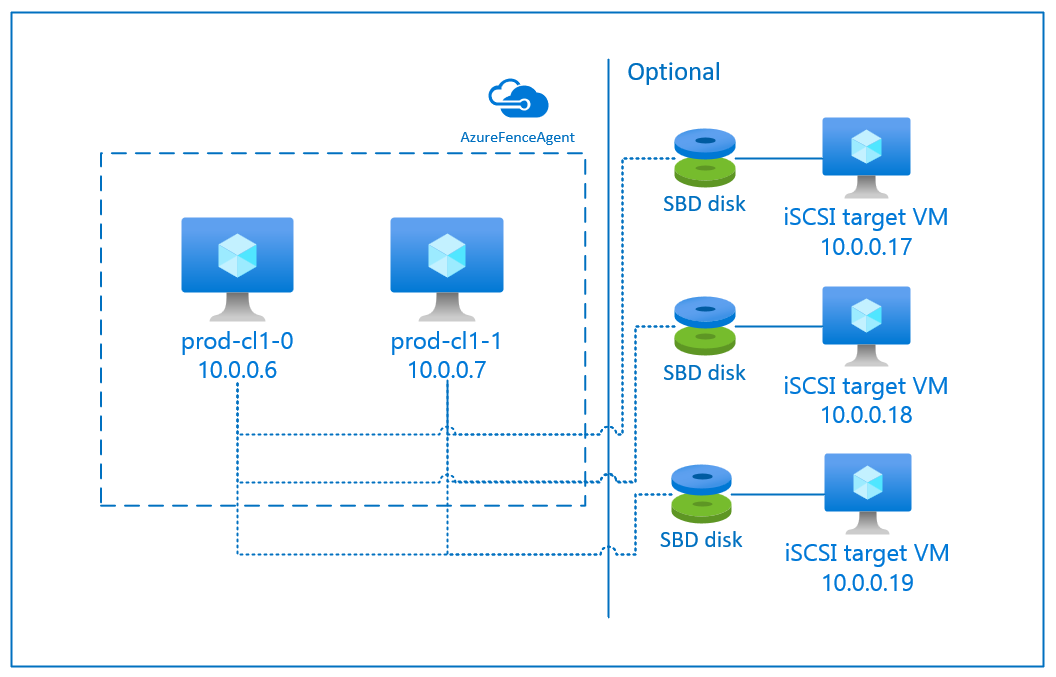
SBD with iSCSI target server
The SBD device requires at least one additional virtual machine (VM) that acts as an Internet Small Compute System Interface (iSCSI) target server and provides an SBD device. These iSCSI target servers can, however, be shared with other pacemaker clusters. The advantage of using an SBD device is that if you're already using SBD devices on-premises, they don't require any changes to how you operate the pacemaker cluster.
You can use up to three SBD devices for a pacemaker cluster to allow an SBD device to become unavailable (for example, during OS patching of the iSCSI target server). If you want to use more than one SBD device per pacemaker, be sure to deploy multiple iSCSI target servers and connect one SBD from each iSCSI target server. We recommend using either one or three SBD device. Pacemaker can't automatically fence a cluster node if only two SBD devices are configured and one them is unavailable. If you want to be able to fence when one iSCSI target server is down, you have to use three SBD devices and, therefore, three iSCSI target servers. That's the most resilient configuration when you're using SBDs.
Important
When you're planning to deploy and configure Linux pacemaker cluster nodes and SBD devices, do not allow the routing between your virtual machines and the VMs that are hosting the SBD devices to pass through any other devices, such as a network virtual appliance (NVA).
Maintenance events and other issues with the NVA can have a negative impact on the stability and reliability of the overall cluster configuration. For more information, see user-defined routing rules.
SBD with Azure shared disk
To configure an SBD device, you need to attach at least one Azure shared disk to all virtual machines that are part of pacemaker cluster. The advantage of SBD device using an Azure shared disk is that you don't need to deploy and configure additional virtual machines.

Here are some important considerations about SBD devices when configuring using Azure Shared Disk:
- An Azure shared disk with Premium SSD is supported as an SBD device.
- SBD devices that use an Azure shared disk are supported on RHEL 8.8 and later.
- SBD devices that use an Azure premium share disk are supported on locally redundant storage (LRS) and zone-redundant storage (ZRS).
- Depending on the type of your deployment, choose the appropriate redundant storage for an Azure shared disk as your SBD device.
- An SBD device using LRS for an Azure premium shared disk (skuName - Premium_LRS) is only supported with regional deployment like availability set.
- An SBD device using ZRS for an Azure premium shared disk (skuName - Premium_ZRS) is recommended with zonal deployment like availability zone, or scale set with FD=1.
- A ZRS for managed disk is currently available in the regions listed in regional availability document.
- The Azure shared disk that you use for SBD devices doesn't need to be large. The maxShares value determines how many cluster nodes can use the shared disk. For example, you can use P1 or P2 disk sizes for your SBD device on two-node cluster such as SAP ASCS/ERS or SAP HANA scale-up.
- For HANA scale-out with HANA system replication (HSR) and pacemaker, you can use an Azure shared disk for SBD devices in clusters with up to five nodes per replication site because of the current limit of maxShares.
- We don't recommend attaching an Azure shared disk SBD device across pacemaker clusters.
- If you use multiple Azure shared disk SBD devices, check on the limit for a maximum number of data disks that can be attached to a VM.
- For more information about limitations for Azure shared disks, carefully review the "Limitations" section of Azure shared disk documentation.
Use an Azure fence agent
You can set up fencing by using an Azure fence agent. Azure fence agent requires managed identities for the cluster VMs or a service principal or managed system identity (MSI) that manages to restart failed nodes via Azure APIs. Azure fence agent doesn't require the deployment of additional virtual machines.
SBD with an iSCSI target server
To use an SBD device that uses an iSCSI target server for fencing, follow the instructions in the next sections.
Set up the iSCSI target server
You first need to create the iSCSI target virtual machines. You can share iSCSI target servers with multiple pacemaker clusters.
Deploy virtual machines that run on supported RHEL OS version, and connect to them via SSH. The VMs don't have to be of large size. VM sizes such as Standard_E2s_v3 or Standard_D2s_v3 are sufficient. Be sure to use Premium storage for the OS disk.
It isn't necessary to use RHEL for SAP with HA and Update Services, or RHEL for SAP Apps OS image for the iSCSI target server. A standard RHEL OS image can be used instead. However, be aware that the support life cycle varies between different OS product releases.
Run following commands on all iSCSI target virtual machines.
Update RHEL.
sudo yum -y updateNote
You might need to reboot the node after you upgrade or update the OS.
Install iSCSI target package.
sudo yum install targetcliStart and configure target to start at boot time.
sudo systemctl start target
sudo systemctl enable target
Open port
3260in the firewallsudo firewall-cmd --add-port=3260/tcp --permanent sudo firewall-cmd --add-port=3260/tcp
Create an iSCSI device on the iSCSI target server
To create the iSCSI disks for your SAP system clusters, execute following commands on every iSCSI target virtual machine. The example illustrates the creation of SBD Devices for several clusters, demonstrating the use of a single iSCSI target server for multiple clusters. The SBD device is configured on the OS disk, so ensure there's enough space.
- ascsnw1: Represents the ASCS/ERS cluster of NW1.
- dbhn1: Represents the database cluster of HN1.
- sap-cl1 and sap-cl2: Hostnames of the NW1 ASCS/ERS cluster nodes.
- hn1-db-0 and hn1-db-1: Hostnames of the database cluster nodes.
In the following instructions, modify the command with your specific hostnames and SIDs as needed.
Create the root folder for all SBD devices.
sudo mkdir /sbdCreate the SBD device for the ASCS/ERS servers of the system NW1.
sudo targetcli backstores/fileio create sbdascsnw1 /sbd/sbdascsnw1 50M write_back=false
sudo targetcli iscsi/ create iqn.2006-04.ascsnw1.local:ascsnw1
sudo targetcli iscsi/iqn.2006-04.ascsnw1.local:ascsnw1/tpg1/luns/ create /backstores/fileio/sbdascsnw1
sudo targetcli iscsi/iqn.2006-04.ascsnw1.local:ascsnw1/tpg1/acls/ create iqn.2006-04.sap-cl1.local:sap-cl1
sudo targetcli iscsi/iqn.2006-04.ascsnw1.local:ascsnw1/tpg1/acls/ create iqn.2006-04.sap-cl2.local:sap-cl2
Create the SBD device for the database cluster of the system HN1.
sudo targetcli backstores/fileio create sbddbhn1 /sbd/sbddbhn1 50M write_back=false
sudo targetcli iscsi/ create iqn.2006-04.dbhn1.local:dbhn1
sudo targetcli iscsi/iqn.2006-04.dbhn1.local:dbhn1/tpg1/luns/ create /backstores/fileio/sbddbhn1
sudo targetcli iscsi/iqn.2006-04.dbhn1.local:dbhn1/tpg1/acls/ create iqn.2006-04.hn1-db-0.local:hn1-db-0
sudo targetcli iscsi/iqn.2006-04.dbhn1.local:dbhn1/tpg1/acls/ create iqn.2006-04.hn1-db-1.local:hn1-db-1
Save the targetcli configuration.
sudo targetcli saveconfigCheck to ensure that everything was set up correctly
sudo targetcli ls

o- / ......................................................................................................................... [...]
  o- backstores .............................................................................................................. [...]
  | o- block .................................................................................................. [Storage Objects: 0]
  | o- fileio ................................................................................................. [Storage Objects: 2]
  | | o- sbdascsnw1 ............................................................... [/sbd/sbdascsnw1 (50.0MiB) write-thru activated]
  | | | o- alua ................................................................................................... [ALUA Groups: 1]
  | | |   o- default_tg_pt_gp ....................................................................... [ALUA state: Active/optimized]
  | | o- sbddbhn1 ................................................................... [/sbd/sbddbhn1 (50.0MiB) write-thru activated]
  | |   o- alua ................................................................................................... [ALUA Groups: 1]
  | |     o- default_tg_pt_gp ....................................................................... [ALUA state: Active/optimized]
  | o- pscsi .................................................................................................. [Storage Objects: 0]
  | o- ramdisk ................................................................................................ [Storage Objects: 0]
  o- iscsi ............................................................................................................ [Targets: 2]
  | o- iqn.2006-04.dbhn1.local:dbhn1 ..................................................................................... [TPGs: 1]
  | | o- tpg1 ............................................................................................... [no-gen-acls, no-auth]
  | |   o- acls .......................................................................................................... [ACLs: 2]
  | |   | o- iqn.2006-04.hn1-db-0.local:hn1-db-0 .................................................................. [Mapped LUNs: 1]
  | |   | | o- mapped_lun0 ............................................................................... [lun0 fileio/sbdhdb (rw)]
  | |   | o- iqn.2006-04.hn1-db-1.local:hn1-db-1 .................................................................. [Mapped LUNs: 1]
  | |   |   o- mapped_lun0 ............................................................................... [lun0 fileio/sbdhdb (rw)]
  | |   o- luns .......................................................................................................... [LUNs: 1]
  | |   | o- lun0 ............................................................. [fileio/sbddbhn1 (/sbd/sbddbhn1) (default_tg_pt_gp)]
  | |   o- portals .................................................................................................... [Portals: 1]
  | |     o- 0.0.0.0:3260 ..................................................................................................... [OK]
  | o- iqn.2006-04.ascsnw1.local:ascsnw1 ................................................................................. [TPGs: 1]
  |   o- tpg1 ............................................................................................... [no-gen-acls, no-auth]
  |     o- acls .......................................................................................................... [ACLs: 2]
  |     | o- iqn.2006-04.sap-cl1.local:sap-cl1 .................................................................... [Mapped LUNs: 1]
  |     | | o- mapped_lun0 ........................................................................... [lun0 fileio/sbdascsers (rw)]
  |     | o- iqn.2006-04.sap-cl2.local:sap-cl2 .................................................................... [Mapped LUNs: 1]
  |     |   o- mapped_lun0 ........................................................................... [lun0 fileio/sbdascsers (rw)]
  |     o- luns .......................................................................................................... [LUNs: 1]
  |     | o- lun0 ......................................................... [fileio/sbdascsnw1 (/sbd/sbdascsnw1) (default_tg_pt_gp)]
  |     o- portals .................................................................................................... [Portals: 1]
  |       o- 0.0.0.0:3260 ..................................................................................................... [OK]
  o- loopback ......................................................................................................... [Targets: 0]
Set up the iSCSI target server SBD device
[A]: Applies to all node. [1]: Applies only to node 1. [2]: Applies only to node 2.
On the cluster nodes, connect and discover iSCSI device that was created in the earlier section. Run the following commands on the nodes of the new cluster that you want to create.
[A] Install or update iSCSI initiator utils on all cluster nodes.
sudo yum install -y iscsi-initiator-utils[A] Install cluster and SBD packages on all cluster nodes.
sudo yum install -y pcs pacemaker sbd fence-agents-sbd[A] Enable iSCSI service.
sudo systemctl enable iscsid iscsi[1] Change the initiator name on the first node of the cluster.
sudo vi /etc/iscsi/initiatorname.iscsi

# Change the content of the file to match the access control ists (ACLs) you used when you created the iSCSI device on the iSCSI target server (for example, for the ASCS/ERS servers)
InitiatorName=iqn.2006-04.sap-cl1.local:sap-cl1
[2] Change the initiator name on the second node of the cluster.
sudo vi /etc/iscsi/initiatorname.iscsi

# Change the content of the file to match the access control ists (ACLs) you used when you created the iSCSI device on the iSCSI target server (for example, for the ASCS/ERS servers)
InitiatorName=iqn.2006-04.sap-cl2.local:sap-cl2
[A] Restart the iSCSI service to apply the changes.
sudo systemctl restart iscsid
sudo systemctl restart iscsi
[A] Connect the iSCSI devices. In the following example, 10.0.0.17 is the IP address of the iSCSI target server, and 3260 is the default port. The target name
iqn.2006-04.ascsnw1.local:ascsnw1get listed when you run the first commandiscsiadm -m discovery.sudo iscsiadm -m discovery --type=st --portal=10.0.0.17:3260 sudo iscsiadm -m node -T iqn.2006-04.ascsnw1.local:ascsnw1 --login --portal=10.0.0.17:3260 sudo iscsiadm -m node -p 10.0.0.17:3260 -T iqn.2006-04.ascsnw1.local:ascsnw1 --op=update --name=node.startup --value=automatic[A] If you using multiple SBD devices, also connect to the second iSCSI target server.
sudo iscsiadm -m discovery --type=st --portal=10.0.0.18:3260
sudo iscsiadm -m node -T iqn.2006-04.ascsnw1.local:ascsnw1 --login --portal=10.0.0.18:3260
sudo iscsiadm -m node -p 10.0.0.18:3260 -T iqn.2006-04.ascsnw1.local:ascsnw1 --op=update --name=node.startup --value=automatic
[A] If you using multiple SBD devices, also connect to the third iSCSI target server.
sudo iscsiadm -m discovery --type=st --portal=10.0.0.19:3260
sudo iscsiadm -m node -T iqn.2006-04.ascsnw1.local:ascsnw1 --login --portal=10.0.0.19:3260
sudo iscsiadm -m node -p 10.0.0.19:3260 -T iqn.2006-04.ascsnw1.local:ascsnw1 --op=update --name=node.startup --value=automatic
[A] Make sure that the iSCSI devices are available and note the device name. In the following example, three iSCSI devices are discovered by connecting the node to three iSCSI target servers.
lsscsi

[0:0:0:0]    disk    Msft     Virtual Disk     1.0   /dev/sde
[1:0:0:0]    disk    Msft     Virtual Disk     1.0   /dev/sda
[1:0:0:1]    disk    Msft     Virtual Disk     1.0   /dev/sdb
[1:0:0:2]    disk    Msft     Virtual Disk     1.0   /dev/sdc
[1:0:0:3]    disk    Msft     Virtual Disk     1.0   /dev/sdd
[2:0:0:0]    disk    LIO-ORG  sbdascsnw1       4.0   /dev/sdf
[3:0:0:0]    disk    LIO-ORG  sbdascsnw1       4.0   /dev/sdh
[4:0:0:0]    disk    LIO-ORG  sbdascsnw1       4.0   /dev/sdg
[A] Retrieve the IDs of the iSCSI devices.
ls -l /dev/disk/by-id/scsi-* | grep -i sdf

# lrwxrwxrwx 1 root root  9 Jul 15 20:21 /dev/disk/by-id/scsi-1LIO-ORG_sbdhdb:85d254ed-78e2-4ec4-8b0d-ecac2843e086 -> ../../sdf
# lrwxrwxrwx 1 root root  9 Jul 15 20:21 /dev/disk/by-id/scsi-3600140585d254ed78e24ec48b0decac2 -> ../../sdf
# lrwxrwxrwx 1 root root  9 Jul 15 20:21 /dev/disk/by-id/scsi-SLIO-ORG_sbdhdb_85d254ed-78e2-4ec4-8b0d-ecac2843e086 -> ../../sdf

ls -l /dev/disk/by-id/scsi-* | grep -i sdh

# lrwxrwxrwx 1 root root  9 Jul 15 20:21 /dev/disk/by-id/scsi-1LIO-ORG_sbdhdb:87122bfc-8a0b-4006-b538-d0a6d6821f04 -> ../../sdh
# lrwxrwxrwx 1 root root  9 Jul 15 20:21 /dev/disk/by-id/scsi-3600140587122bfc8a0b4006b538d0a6d -> ../../sdh
# lrwxrwxrwx 1 root root  9 Jul 15 20:21 /dev/disk/by-id/scsi-SLIO-ORG_sbdhdb_87122bfc-8a0b-4006-b538-d0a6d6821f04 -> ../../sdh

ls -l /dev/disk/by-id/scsi-* | grep -i sdg

# lrwxrwxrwx 1 root root  9 Jul 15 20:21 /dev/disk/by-id/scsi-1LIO-ORG_sbdhdb:d2ddc548-060c-49e7-bb79-2bb653f0f34a -> ../../sdg
# lrwxrwxrwx 1 root root  9 Jul 15 20:21 /dev/disk/by-id/scsi-36001405d2ddc548060c49e7bb792bb65 -> ../../sdg
# lrwxrwxrwx 1 root root  9 Jul 15 20:21 /dev/disk/by-id/scsi-SLIO-ORG_sbdhdb_d2ddc548-060c-49e7-bb79-2bb653f0f34a -> ../../sdg
The command lists three device IDs for every SBD device. We recommend using the ID that starts with scsi-3. In the preceding example, the IDs are:
- /dev/disk/by-id/scsi-3600140585d254ed78e24ec48b0decac2
- /dev/disk/by-id/scsi-3600140587122bfc8a0b4006b538d0a6d
- /dev/disk/by-id/scsi-36001405d2ddc548060c49e7bb792bb65
[1] Create the SBD device.
Use the device ID of the iSCSI devices to create the new SBD devices on the first cluster node.
sudo sbd -d /dev/disk/by-id/scsi-3600140585d254ed78e24ec48b0decac2 -1 60 -4 120 createAlso create the second and third SBD devices if you want to use more than one.
sudo sbd -d /dev/disk/by-id/scsi-3600140587122bfc8a0b4006b538d0a6d -1 60 -4 120 create
sudo sbd -d /dev/disk/by-id/scsi-36001405d2ddc548060c49e7bb792bb65 -1 60 -4 120 create
[A] Adapt the SBD configuration
Open the SBD config file.
sudo vi /etc/sysconfig/sbdChange the property of the SBD device, enable the pacemaker integration, and change the start mode of SBD.
[...]
SBD_DEVICE="/dev/disk/by-id/scsi-3600140585d254ed78e24ec48b0decac2;/dev/disk/by-id/scsi-3600140587122bfc8a0b4006b538d0a6d;/dev/disk/by-id/scsi-36001405d2ddc548060c49e7bb792bb65"
[...]
SBD_PACEMAKER=yes
[...]
SBD_STARTMODE=always
[...]
SBD_DELAY_START=yes
[...]
[A] Run the following command to load the
softdogmodule.modprobe softdog[A] Run the following command to ensure
softdogis automatically loaded after a node reboot.echo softdog > /etc/modules-load.d/watchdog.conf systemctl restart systemd-modules-load[A] The SBD service timeout value is set to 90 s by default. However, if the
SBD_DELAY_STARTvalue is set toyes, the SBD service will delay its start until after themsgwaittimeout. Therefore, the SBD service timeout value should exceed themsgwaittimeout whenSBD_DELAY_STARTis enabled.sudo mkdir /etc/systemd/system/sbd.service.d echo -e "[Service]\nTimeoutSec=144" | sudo tee /etc/systemd/system/sbd.service.d/sbd_delay_start.conf sudo systemctl daemon-reload systemctl show sbd | grep -i timeout # TimeoutStartUSec=2min 24s # TimeoutStopUSec=2min 24s
SBD with an Azure shared disk
This section applies only if you want to use an SBD Device with an Azure shared disk.
Configure Azure shared disk with PowerShell
To create and attach an Azure shared disk with PowerShell, execute following instruction. If you want to deploy resources by using the Azure CLI or the Azure portal, you can also refer to Deploy a ZRS disk.
$ResourceGroup = "MyResourceGroup"
$Location = "MyAzureRegion"
$DiskSizeInGB = 4
$DiskName = "SBD-disk1"
$ShareNodes = 2
$LRSSkuName = "Premium_LRS"
$ZRSSkuName = "Premium_ZRS"
$vmNames = @("prod-cl1-0", "prod-cl1-1")  # VMs to attach the disk

# ZRS Azure shared disk: Configure an Azure shared disk with ZRS for a premium shared disk
$zrsDiskConfig = New-AzDiskConfig -Location $Location -SkuName $ZRSSkuName -CreateOption Empty -DiskSizeGB $DiskSizeInGB -MaxSharesCount $ShareNodes
$zrsDataDisk = New-AzDisk -ResourceGroupName $ResourceGroup -DiskName $DiskName -Disk $zrsDiskConfig

# Attach ZRS disk to cluster VMs
foreach ($vmName in $vmNames) {
  $vm = Get-AzVM -ResourceGroupName $resourceGroup -Name $vmName
  Add-AzVMDataDisk -VM $vm -Name $diskName -CreateOption Attach -ManagedDiskId $zrsDataDisk.Id -Lun 0
  Update-AzVM -VM $vm -ResourceGroupName $resourceGroup -Verbose
}

# LRS Azure shared disk: Configure an Azure shared disk with LRS for a premium shared disk
$lrsDiskConfig = New-AzDiskConfig -Location $Location -SkuName $LRSSkuName -CreateOption Empty -DiskSizeGB $DiskSizeInGB -MaxSharesCount $ShareNodes
$lrsDataDisk = New-AzDisk -ResourceGroupName $ResourceGroup -DiskName $DiskName -Disk $lrsDiskConfig

# Attach LRS disk to cluster VMs
foreach ($vmName in $vmNames) {
  $vm = Get-AzVM -ResourceGroupName $resourceGroup -Name $vmName
  Add-AzVMDataDisk -VM $vm -Name $diskName -CreateOption Attach -ManagedDiskId $lrsDataDisk.Id -Lun 0
  Update-AzVM -VM $vm -ResourceGroupName $resourceGroup -Verbose
}
Set up an Azure shared disk SBD device
[A] Install cluster and SBD packages on all cluster nodes.
sudo yum install -y pcs pacemaker sbd fence-agents-sbd[A] Make sure the attached disk is available.
lsblk

# NAME              MAJ:MIN RM  SIZE RO TYPE MOUNTPOINT
# sda                 8:0    0    4G  0 disk
# sdb                 8:16   0   64G  0 disk
# ├─sdb1              8:17   0  500M  0 part /boot
# ├─sdb2              8:18   0   63G  0 part
# │ ├─rootvg-tmplv  253:0    0    2G  0 lvm  /tmp
# │ ├─rootvg-usrlv  253:1    0   10G  0 lvm  /usr
# │ ├─rootvg-homelv 253:2    0    1G  0 lvm  /home
# │ ├─rootvg-varlv  253:3    0    8G  0 lvm  /var
# │ └─rootvg-rootlv 253:4    0    2G  0 lvm  /
# ├─sdb14             8:30   0    4M  0 part
# └─sdb15             8:31   0  495M  0 part /boot/efi
# sr0                11:0    1 1024M  0 rom

lsscsi

# [0:0:0:0]    disk    Msft     Virtual Disk     1.0   /dev/sdb
# [0:0:0:2]    cd/dvd  Msft     Virtual DVD-ROM  1.0   /dev/sr0
# [1:0:0:0]    disk    Msft     Virtual Disk     1.0   /dev/sda
# [1:0:0:1]    disk    Msft     Virtual Disk     1.0   /dev/sdc
[A] Retrieve the device ID of the attached shared disk.
ls -l /dev/disk/by-id/scsi-* | grep -i sda

# lrwxrwxrwx 1 root root  9 Jul 15 22:24 /dev/disk/by-id/scsi-14d534654202020200792c2f5cc7ef14b8a7355cb3cef0107 -> ../../sda
# lrwxrwxrwx 1 root root  9 Jul 15 22:24 /dev/disk/by-id/scsi-3600224800792c2f5cc7e55cb3cef0107 -> ../../sda
The command list device ID for the attached shared disk. We recommend using the ID that starts with scsi-3. In this example, the ID is /dev/disk/by-id/scsi-3600224800792c2f5cc7e55cb3cef0107.
[1] Create the SBD device
# Use the device ID from step 3 to create the new SBD device on the first cluster node
sudo sbd -d /dev/disk/by-id/scsi-3600224800792c2f5cc7e55cb3cef0107 -1 60 -4 120 create
[A] Adapt the SBD configuration
Open the SBD config file.
sudo vi /etc/sysconfig/sbdChange the property of the SBD device, enable the pacemaker integration, and change the start mode of SBD
[...]
SBD_DEVICE="/dev/disk/by-id/scsi-3600224800792c2f5cc7e55cb3cef0107"
[...]
SBD_PACEMAKER=yes
[...]
SBD_STARTMODE=always
[...]
SBD_DELAY_START=yes
[...]
[A] Run the following command to load the
softdogmodule.modprobe softdog[A] Run the following command to ensure
softdogis automatically loaded after a node reboot.echo softdog > /etc/modules-load.d/watchdog.conf systemctl restart systemd-modules-load[A] The SBD service timeout value is set to 90 seconds by default. However, if the
SBD_DELAY_STARTvalue is set toyes, the SBD service will delay its start until after themsgwaittimeout. Therefore, the SBD service timeout value should exceed themsgwaittimeout whenSBD_DELAY_STARTis enabled.sudo mkdir /etc/systemd/system/sbd.service.d echo -e "[Service]\nTimeoutSec=144" | sudo tee /etc/systemd/system/sbd.service.d/sbd_delay_start.conf sudo systemctl daemon-reload systemctl show sbd | grep -i timeout # TimeoutStartUSec=2min 24s # TimeoutStopUSec=2min 24s
Azure fence agent configuration
The fencing device uses either a managed identity for Azure resource or a service principal to authorize against Azure. Depending on the identity management method, follow the appropriate procedures -
Configure identity management
Use managed identity or service principal.
To create a managed identity (MSI), create a system-assigned managed identity for each VM in the cluster. If a system-assigned managed identity already exists, then it would be used. Don't use user-assigned managed identities with Pacemaker at this time. A fence device, based on managed identity, is supported on RHEL 7.9 and RHEL 8.x/RHEL 9.x.
Create a custom role for the fence agent
Both the managed identity and the service principal don't have permissions to access your Azure resources by default. You need to give the managed identity or service principal permissions to start and stop (power-off) all VMs of the cluster. If you haven't already created the custom role, you can create it by using PowerShell or the Azure CLI.
Use the following content for the input file. You need to adapt the content to your subscriptions, that is, replace
xxxxxxxx-xxxx-xxxx-xxxx-xxxxxxxxxxxxandyyyyyyyy-yyyy-yyyy-yyyy-yyyyyyyyyyyywith the IDs of your subscription. If you only have one subscription, remove the second entry inAssignableScopes.{ "Name": "Linux Fence Agent Role", "description": "Allows to power-off and start virtual machines", "assignableScopes": [ "/subscriptions/xxxxxxxx-xxxx-xxxx-xxxx-xxxxxxxxxxxx", "/subscriptions/yyyyyyyy-yyyy-yyyy-yyyy-yyyyyyyyyyyy" ], "actions": [ "Microsoft.Compute/*/read", "Microsoft.Compute/virtualMachines/powerOff/action", "Microsoft.Compute/virtualMachines/start/action" ], "notActions": [], "dataActions": [], "notDataActions": [] }Assign the custom role
Use managed identity or service principal.
Assign the custom role
Linux Fence Agent Rolethat was created in the last section to each managed identity of the cluster VMs. Each VM system-assigned managed identity needs the role assigned for every cluster VM's resource. For more information, see Assign a managed identity access to a resource by using the Azure portal. Verify that each VM's managed identity role assignment contains all the cluster VMs.Important
Be aware that assignment and removal of authorization with managed identities can be delayed until effective.
Cluster installation
Differences in the commands or the configuration between RHEL 7 and RHEL 8/RHEL 9 are marked in the document.
[A] Install the RHEL HA add-on.
sudo yum install -y pcs pacemaker nmap-ncat[A] On RHEL 9.x, install the resource agents for cloud deployment.
sudo yum install -y resource-agents-cloud[A] Install the fence-agents package if you're using a fencing device based on Azure fence agent.
sudo yum install -y fence-agents-azure-armImportant
We recommend the following versions of the Azure fence agent (or later) for customers who want to use managed identities for Azure resources instead of service principal names for the fence agent:
- RHEL 8.4: fence-agents-4.2.1-54.el8.
- RHEL 8.2: fence-agents-4.2.1-41.el8_2.4
- RHEL 8.1: fence-agents-4.2.1-30.el8_1.4
- RHEL 7.9: fence-agents-4.2.1-41.el7_9.4.
Important
On RHEL 9, we recommend the following package versions (or later) to avoid issues with the Azure fence agent:
- fence-agents-4.10.0-20.el9_0.7
- fence-agents-common-4.10.0-20.el9_0.6
- ha-cloud-support-4.10.0-20.el9_0.6.x86_64.rpm
Check the version of the Azure fence agent. If necessary, update it to the minimum required version or later.
# Check the version of the Azure Fence Agent
sudo yum info fence-agents-azure-arm
Important
If you need to update the Azure fence agent, and if you're using a custom role, make sure to update the custom role to include the action powerOff. For more information, see Create a custom role for the fence agent.
[A] Set up hostname resolution.
You can either use a DNS server or modify the
/etc/hostsfile on all nodes. This example shows how to use the/etc/hostsfile. Replace the IP address and the hostname in the following commands.Important
If you're using hostnames in the cluster configuration, it's vital to have reliable hostname resolution. The cluster communication fails if the names aren't available, which can lead to cluster failover delays.
The benefit of using
/etc/hostsis that your cluster becomes independent of DNS, which could be a single point of failures too.sudo vi /etc/hostsInsert the following lines to
/etc/hosts. Change the IP address and hostname to match your environment.# IP address of the first cluster node 10.0.0.6 prod-cl1-0 # IP address of the second cluster node 10.0.0.7 prod-cl1-1[A] Change the
haclusterpassword to the same password.sudo passwd hacluster[A] Add firewall rules for Pacemaker.
Add the following firewall rules to all cluster communication between the cluster nodes.
sudo firewall-cmd --add-service=high-availability --permanent
sudo firewall-cmd --add-service=high-availability
[A] Enable basic cluster services.
Run the following commands to enable the Pacemaker service and start it.
sudo systemctl start pcsd.service
sudo systemctl enable pcsd.service
[1] Create a Pacemaker cluster.
Run the following commands to authenticate the nodes and create the cluster. Set the token to 30000 to allow memory preserving maintenance. For more information, see this article for Linux.
If you're building a cluster on RHEL 7.x, use the following commands:
sudo pcs cluster auth prod-cl1-0 prod-cl1-1 -u hacluster
sudo pcs cluster setup --name nw1-azr prod-cl1-0 prod-cl1-1 --token 30000
sudo pcs cluster start --all
If you're building a cluster on RHEL 8.x/RHEL 9.x, use the following commands:
sudo pcs host auth prod-cl1-0 prod-cl1-1 -u hacluster
sudo pcs cluster setup nw1-azr prod-cl1-0 prod-cl1-1 totem token=30000
sudo pcs cluster start --all
Verify the cluster status by running the following command:
# Run the following command until the status of both nodes is online
sudo pcs status

# Cluster name: nw1-azr
# WARNING: no stonith devices and stonith-enabled is not false
# Stack: corosync
# Current DC: prod-cl1-1 (version 1.1.18-11.el7_5.3-2b07d5c5a9) - partition with quorum
# Last updated: Fri Aug 17 09:18:24 2018
# Last change: Fri Aug 17 09:17:46 2018 by hacluster via crmd on prod-cl1-1
#
# 2 nodes configured
# 0 resources configured
#
# Online: [ prod-cl1-0 prod-cl1-1 ]
#
# No resources
#
# Daemon Status:
#   corosync: active/disabled
#   pacemaker: active/disabled
#   pcsd: active/enabled
[A] Set expected votes.
# Check the quorum votes
pcs quorum status

# If the quorum votes are not set to 2, execute the next command
sudo pcs quorum expected-votes 2
Tip
If you're building a multinode cluster, that is, a cluster with more than two nodes, don't set the votes to 2.
[1] Allow concurrent fence actions.
sudo pcs property set concurrent-fencing=true
Create a fencing device on the Pacemaker cluster
Tip
- To avoid fence races within a two-node pacemaker cluster, you can configure the
priority-fencing-delaycluster property. This property introduces additional delay in fencing a node that has higher total resource priority when a split-brain scenario occurs. For more information, see Can Pacemaker fence the cluster node with the fewest running resources?. - The property
priority-fencing-delayis applicable for Pacemaker version 2.0.4-6.el8 or higher and on a two-node cluster. If you configure thepriority-fencing-delaycluster property, you don't need to set thepcmk_delay_maxproperty. But if the Pacemaker version is less than 2.0.4-6.el8, you need to set thepcmk_delay_maxproperty. - For instructions on how to set the
priority-fencing-delaycluster property, see the respective SAP ASCS/ERS and SAP HANA scale-up HA documents.
Based on the selected fencing mechanism, follow only one section for relevant instructions: SBD as fencing device or Azure fence agent as fencing device.
SBD as fencing device
[A] Enable SBD service
sudo systemctl enable sbd[1] For the SBD device configured using iSCSI target servers or Azure shared disk, run the following commands.
sudo pcs property set stonith-timeout=144
sudo pcs property set stonith-enabled=true

# Replace the device IDs with your device ID.
pcs stonith create sbd fence_sbd \
devices=/dev/disk/by-id/scsi-3600140585d254ed78e24ec48b0decac2,/dev/disk/by-id/scsi-3600140587122bfc8a0b4006b538d0a6d,/dev/disk/by-id/scsi-36001405d2ddc548060c49e7bb792bb65 \
op monitor interval=600 timeout=15
[1] Restart the cluster
sudo pcs cluster stop --all

# It would take time to start the cluster as "SBD_DELAY_START" is set to "yes"
sudo pcs cluster start --all
Note
If you encounter following error while starting the pacemaker cluster, you can disregard the message. Alternatively, you can start the cluster using the command
pcs cluster start --all --request-timeout 140.Error: unable to start all nodes node1/node2: Unable to connect to node1/node2, check if pcsd is running there or try setting higher timeout with
--request-timeoutoption (Operation timed out after 60000 milliseconds with 0 bytes received)
Azure fence agent as fencing device
[1] After you've assigned roles to both cluster nodes, you can configure the fencing devices in the cluster.
sudo pcs property set stonith-timeout=900
sudo pcs property set stonith-enabled=true
[1] Run the appropriate command depending on whether you're using a managed identity or a service principal for the Azure fence agent.
Note
The option
pcmk_host_mapis only required in the command if the RHEL hostnames and the Azure VM names are not identical. Specify the mapping in the format hostname:vm-name.Refer to the bold section in the command. For more information, see What format should I use to specify node mappings to fencing devices in pcmk_host_map?.
For RHEL 7.x, use the following command to configure the fence device:
sudo pcs stonith create rsc_st_azure fence_azure_arm msi=true resourceGroup="resource group" \
subscriptionId="subscription id" pcmk_host_map="prod-cl1-0:prod-cl1-0-vm-name;prod-cl1-1:prod-cl1-1-vm-name" \
power_timeout=240 pcmk_reboot_timeout=900 pcmk_monitor_timeout=120 pcmk_monitor_retries=4 pcmk_action_limit=3 pcmk_delay_max=15 \
op monitor interval=3600
For RHEL 8.x/9.x, use the following command to configure the fence device:
# Run following command if you are setting up fence agent on (two-node cluster and pacemaker version greater than 2.0.4-6.el8) OR (HANA scale out)
sudo pcs stonith create rsc_st_azure fence_azure_arm msi=true resourceGroup="resource group" \
subscriptionId="subscription id" pcmk_host_map="prod-cl1-0:prod-cl1-0-vm-name;prod-cl1-1:prod-cl1-1-vm-name" \
power_timeout=240 pcmk_reboot_timeout=900 pcmk_monitor_timeout=120 pcmk_monitor_retries=4 pcmk_action_limit=3 \
op monitor interval=3600

# Run following command if you are setting up fence agent on (two-node cluster and pacemaker version less than 2.0.4-6.el8)
sudo pcs stonith create rsc_st_azure fence_azure_arm msi=true resourceGroup="resource group" \
subscriptionId="subscription id" pcmk_host_map="prod-cl1-0:prod-cl1-0-vm-name;prod-cl1-1:prod-cl1-1-vm-name" \
power_timeout=240 pcmk_reboot_timeout=900 pcmk_monitor_timeout=120 pcmk_monitor_retries=4 pcmk_action_limit=3 pcmk_delay_max=15 \
op monitor interval=3600
If you're using a fencing device based on service principal configuration, read Change from SPN to MSI for Pacemaker clusters by using Azure fencing and learn how to convert to managed identity configuration.
The monitoring and fencing operations are deserialized. As a result, if there's a longer running monitoring operation and simultaneous fencing event, there's no delay to the cluster failover because the monitoring operation is already running.
Tip
The Azure fence agent requires outbound connectivity to public endpoints. For more information along with possible solutions, see Public endpoint connectivity for VMs using standard ILB.
Configure Pacemaker for Azure scheduled events
Azure offers scheduled events. Scheduled events are sent via the metadata service and allow time for the application to prepare for such events.
The Pacemaker resource agent azure-events-az monitors for scheduled Azure events. If events are detected and the resource agent determines that another cluster node is available, it sets a cluster health attribute.
When the cluster health attribute is set for a node, the location constraint triggers and all resources with names that don't start with health- are migrated away from the node with the scheduled event. After the affected cluster node is free of running cluster resources, the scheduled event is acknowledged and can execute its action, such as a restart.
[A] Make sure that the package for the
azure-events-azagent is already installed and up to date.RHEL 8.x: sudo dnf info resource-agents RHEL 9.x: sudo dnf info resource-agents-cloudMinimum version requirements:
- RHEL 8.4:
resource-agents-4.1.1-90.13 - RHEL 8.6:
resource-agents-4.9.0-16.9 - RHEL 8.8:
resource-agents-4.9.0-40.1 - RHEL 9.0:
resource-agents-cloud-4.10.0-9.6 - RHEL 9.2 and newer:
resource-agents-cloud-4.10.0-34.1
- RHEL 8.4:
[1] Configure the resources in Pacemaker.
#Place the cluster in maintenance mode
sudo pcs property set maintenance-mode=true
[1] Set the Pacemaker cluster health-node strategy and constraint.
sudo pcs property set node-health-strategy=custom

sudo pcs constraint location 'regexp%!health-.*' \
rule score-attribute='#health-azure' \
defined '#uname'
Important
Don't define any other resources in the cluster starting with
health-besides the resources described in the next steps.[1] Set the initial value of the cluster attributes. Run for each cluster node and for scale-out environments including majority maker VM.
sudo crm_attribute --node prod-cl1-0 --name '#health-azure' --update 0
sudo crm_attribute --node prod-cl1-1 --name '#health-azure' --update 0
[1] Configure the resources in Pacemaker. Make sure the resources start with
health-azure.sudo pcs resource create health-azure-events \ ocf:heartbeat:azure-events-az \ op monitor interval=10s timeout=240s \ op start timeout=10s start-delay=90s sudo pcs resource clone health-azure-events allow-unhealthy-nodes=true failure-timeout=120sTake the Pacemaker cluster out of maintenance mode.
sudo pcs property set maintenance-mode=falseClear any errors during enablement and verify that the
health-azure-eventsresources have started successfully on all cluster nodes.sudo pcs resource cleanupFirst-time query execution for scheduled events can take up to two minutes. Pacemaker testing with scheduled events can use reboot or redeploy actions for the cluster VMs. For more information, see Scheduled events.
Optional fencing configuration
Tip
This section is only applicable if you want to configure the special fencing device fence_kdump.
If you need to collect diagnostic information within the VM, it might be useful to configure another fencing device based on the fence agent fence_kdump. The fence_kdump agent can detect that a node entered kdump crash recovery and can allow the crash recovery service to complete before other fencing methods are invoked. Note that fence_kdump isn't a replacement for traditional fence mechanisms, like the SBD or Azure fence agent, when you're using Azure VMs.
Important
Be aware that when fence_kdump is configured as a first-level fencing device, it introduces delays in the fencing operations and, respectively, delays in the application resources failover.
If a crash dump is successfully detected, the fencing is delayed until the crash recovery service completes. If the failed node is unreachable or if it doesn't respond, the fencing is delayed by time determined, the configured number of iterations, and the fence_kdump timeout. For more information, see How do I configure fence_kdump in a Red Hat Pacemaker cluster?.
The proposed fence_kdump timeout might need to be adapted to the specific environment.
We recommend that you configure fence_kdump fencing only when necessary to collect diagnostics within the VM and always in combination with traditional fence methods, such as SBD or Azure fence agent.
The following Red Hat KB articles contain important information about configuring fence_kdump fencing:
- See How do I configure fence_kdump in a Red Hat Pacemaker cluster?.
- See How to configure/manage fencing levels in an RHEL cluster with Pacemaker.
- See fence_kdump fails with "timeout after X seconds" in an RHEL 6 or 7 HA cluster with kexec-tools older than 2.0.14.
- For information on how to change the default timeout, see How do I configure kdump for use with the RHEL 6, 7, 8 HA Add-On?.
- For information on how to reduce failover delay when you use
fence_kdump, see Can I reduce the expected delay of failover when adding fence_kdump configuration?.
Run the following optional steps to add fence_kdump as a first-level fencing configuration, in addition to the Azure fence agent configuration.
[A] Verify that
kdumpis active and configured.systemctl is-active kdump # Expected result # active[A] Install the
fence_kdumpfence agent.yum install fence-agents-kdump[1] Create a
fence_kdumpfencing device in the cluster.pcs stonith create rsc_st_kdump fence_kdump pcmk_reboot_action="off" pcmk_host_list="prod-cl1-0 prod-cl1-1" timeout=30[1] Configure fencing levels so that the
fence_kdumpfencing mechanism is engaged first.pcs stonith create rsc_st_kdump fence_kdump pcmk_reboot_action="off" pcmk_host_list="prod-cl1-0 prod-cl1-1" pcs stonith level add 1 prod-cl1-0 rsc_st_kdump pcs stonith level add 1 prod-cl1-1 rsc_st_kdump # Replace <stonith-resource-name> to the resource name of the STONITH resource configured in your pacemaker cluster (example based on above configuration - sbd or rsc_st_azure) pcs stonith level add 2 prod-cl1-0 <stonith-resource-name> pcs stonith level add 2 prod-cl1-1 <stonith-resource-name> # Check the fencing level configuration pcs stonith level # Example output # Target: prod-cl1-0 # Level 1 - rsc_st_kdump # Level 2 - <stonith-resource-name> # Target: prod-cl1-1 # Level 1 - rsc_st_kdump # Level 2 - <stonith-resource-name>[A] Allow the required ports for
fence_kdumpthrough the firewall.firewall-cmd --add-port=7410/udp firewall-cmd --add-port=7410/udp --permanent[A] Perform the
fence_kdump_nodesconfiguration in/etc/kdump.confto avoidfence_kdumpfrom failing with a timeout for somekexec-toolsversions. For more information, see fence_kdump times out when fence_kdump_nodes isn't specified with kexec-tools version 2.0.15 or later and fence_kdump fails with "timeout after X seconds" in a RHEL 6 or 7 High Availability cluster with kexec-tools versions older than 2.0.14. The example configuration for a two-node cluster is presented here. After you make a change in/etc/kdump.conf, the kdump image must be regenerated. To regenerate, restart thekdumpservice.vi /etc/kdump.conf # On node prod-cl1-0 make sure the following line is added fence_kdump_nodes prod-cl1-1 # On node prod-cl1-1 make sure the following line is added fence_kdump_nodes prod-cl1-0 # Restart the service on each node systemctl restart kdump[A] Ensure that the
initramfsimage file contains thefence_kdumpandhostsfiles. For more information, see How do I configure fence_kdump in a Red Hat Pacemaker cluster?.lsinitrd /boot/initramfs-$(uname -r)kdump.img | egrep "fence|hosts" # Example output # -rw-r--r-- 1 root root 208 Jun 7 21:42 etc/hosts # -rwxr-xr-x 1 root root 15560 Jun 17 14:59 usr/libexec/fence_kdump_sendTest the configuration by crashing a node. For more information, see How do I configure fence_kdump in a Red Hat Pacemaker cluster?.
Important
If the cluster is already in productive use, plan the test accordingly because crashing a node has an impact on the application.
echo c > /proc/sysrq-trigger
Next steps
- See Azure Virtual Machines planning and implementation for SAP.
- See Azure Virtual Machines deployment for SAP.
- See Azure Virtual Machines DBMS deployment for SAP.
- To learn how to establish HA and plan for disaster recovery of SAP HANA on Azure VMs, see High Availability of SAP HANA on Azure Virtual Machines.
Tilbakemeldinger
Kommer snart: Gjennom 2024 faser vi ut GitHub Issues som tilbakemeldingsmekanisme for innhold, og erstatter det med et nytt system for tilbakemeldinger. Hvis du vil ha mer informasjon, kan du se: https://aka.ms/ContentUserFeedback.
Send inn og vis tilbakemelding for