Create dependency diagrams from your code
To visualize your software system's high-level, logical architecture, create a dependency diagram in Visual Studio. To make sure that your code stays consistent with this design, validate your code with a dependency diagram. You can create dependency diagrams for Visual C# and Visual Basic projects. To see which editions of Visual Studio support this feature, see Edition support for architecture and modeling tools.
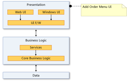
A dependency diagram lets you organize Visual Studio solution items into logical, abstract groups called layers. You can use layers to describe major tasks that these artifacts perform or the system's major components.
Each layer might contain other layers that describe more detailed tasks. You can also specify the intended or existing dependencies between layers. These dependencies, represented as arrows, show the layers that use or can use the functionality represented by other layers. To maintain architectural control of the code, show the intended dependencies on the diagram and then validate the code against the diagram.
Video: Validate your architecture dependencies in real time
Create a dependency diagram
Before you create a dependency diagram, ensure that your solution has a modeling project.
Important
Don't add, drag, or copy an existing dependency diagram from one modeling project to another modeling project, or to another place in the solution. This preserves the references from the original diagram, even if you change the diagram. This also prevents layer validation from working correctly and might cause other issues, such as missing elements or other errors when you try to open the diagram.
Instead, add a new dependency diagram to the modeling project. Copy the elements from the source diagram to the new diagram. Save both, the modeling project and the new dependency diagram.
Add a new dependency diagram to a modeling project
Note
Dependency diagrams for .NET Core projects are supported starting Visual Studio 2019 version 16.2.
On the Architecture menu, choose New Dependency Diagram.
Under Templates, choose dependency diagram.
Name the diagram.
In Add to Modeling Project, browse to and select an existing modeling project in your solution.
-or-
Choose Create a new modeling project to add a new modeling project to the solution.
Note
The dependency diagram must exist inside a modeling project. However, you can link it to items anywhere in the solution.
Make sure to save both, the modeling project and the dependency diagram.
Drag and drop, or copy and paste, from a Code Map
Generate a Code Map for the solution using the Architecture menu.
Consider applying a Code Map filter to remove solution folders and "Test Assets" if you only want to enforce dependencies in product code.
On the generated Code Map, remove the "External" node, or expand it to show external assemblies, depending on whether you want to enforce namespace dependencies. Delete non-required assemblies from the Code Map.
Create a new Dependency Diagram for the solution using the Architecture menu.
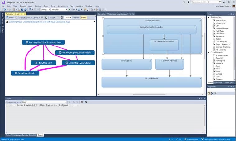
Select all the nodes on the Code Map (use Ctrl + A, or use the rubber band selection by pressing the Shift key before you click, drag, and release).
Drag and drop, or copy and paste, the selected elements to the new Dependency Validation diagram.
This shows the current app architecture. Decide what you want the architecture to be and modify the dependency diagram accordingly.
Create layers from artifacts
You can create layers from Visual Studio solution items, such as projects, code files, namespaces, classes, and methods. This automatically creates links between layers and items, including them in the layer validation process.
You can link layers to items that don't support validation, such as Word documents or PowerPoint presentations. This lets you associate a layer with specifications or plans. You can also link layers to files in projects that are shared across multiple apps, but the validation process won't include those layers, which appear with generic names such as "Layer 1" and "Layer 2".
To see if a linked item supports validation, open Layer Explorer and examine the Supports Validation property of the item. See Managing links to artifacts.
| To | Follow these steps |
|---|---|
| Create a layer for a single artifact |
Important: Dragging binary files to the dependency diagram doesn't automatically add their references to modeling project. Manually add the binary files that you want to validate to the modeling project. To add binary files to the modeling project
|
| Create a single layer for all selected artifacts | Drag all the artifacts to the dependency diagram at the same time. A layer appears on the diagram and is linked to all of the artifacts. |
| Create a layer for each selected artifact | Press and hold the SHIFT key while you drag all of the artifacts to the dependency diagram at the same time. Note: If you use the SHIFT key to select a range of items, release the key after you select the artifacts. Press and hold it again when you drag the artifacts to the diagram. A layer for each artifact appears on the diagram and is linked to each artifact. |
| Add an artifact to a layer | Drag the artifact to the layer. |
| Create a new unlinked layer | In the Toolbox, expand the Dependency Diagram section, and then drag a Layer to the dependency diagram. To add multiple layers, double-click the tool. When you're done, choose the Pointer tool or press the ESC key. - or - Open the shortcut menu for the dependency diagram, choose Add, and then choose Layer. |
| Create nested layers | Drag an existing layer onto another layer. - or - Open the shortcut menu for a layer, choose Add, and then choose Layer. |
| Create a new layer that contains two or more existing layers | Select the layers, open the shortcut menu for your selection, and then choose Group. |
| Change the color of a layer | Set its Color property to the color that you want. |
| Specify that artifacts associated with a layer shouldn't belong to the specified namespaces | Type the namespaces in the layer's Forbidden Namespaces property. Use a semicolon (;) to separate the namespaces. |
| Specify that artifacts associated with a layer can't depend on the specified namespaces | Type the namespaces in the layer's Forbidden Namespace Dependencies property. Use a semicolon (;) to separate the namespaces. |
| Specify that artifacts associated with a layer must belong to one of the specified namespaces | Type the namespace in the layer's Required Namespaces property. Use a semicolon (;) to separate the namespaces. |
The number on a layer indicates the number of artifacts that are linked to the layer. However, when reading this number, remember:
If a layer links to an artifact that contains other artifacts, but the layer doesn't link directly to the other artifacts, then the number includes only the linked artifact. However, the other artifacts are included for analysis during layer validation.
For example, if a layer is linked to a single namespace, then the number of linked artifacts is 1, even if the namespace contains classes. If the layer also has links to each class in the namespace, then the number will include the linked classes.
If a layer contains other layers that are linked to artifacts, then the container layer is also linked to those artifacts, even though the number on the container layer doesn't include those artifacts.
Manage links between layers and artifacts
On the dependency diagram, open the shortcut menu for the layer, and then choose View Links.
Layer Explorer shows the artifact links for the selected layer.
Use the following tasks to manage these links:
| To | In Layer Explorer |
|---|---|
| Delete the link between the layer and an artifact | Open the shortcut menu for the artifact link, and then choose Delete. |
| Move the link from one layer to another | Drag the artifact link to an existing layer on the diagram. - or - 1. Open the shortcut menu for the artifact link, and then choose Cut. 2. On the dependency diagram, open the shortcut menu for the layer, and then choose Paste. |
| Copy the link from one layer to another | 1. Open the shortcut menu for the artifact link, and then choose Copy. 2. On the dependency diagram, open the shortcut menu for the layer, and then choose Paste. |
| Create a new layer from an existing artifact link | Drag the artifact link to a blank area on the diagram. |
| Verify that a linked artifact supports validation against the dependency diagram. | Look at the Supports Validation column for the artifact link. |
Reverse-engineer existing dependencies
A dependency exists wherever an artifact that is associated with one layer has a reference to an artifact that is associated with another layer. For example, a class in one layer declares a variable that has a class in another layer. You can reverse-engineer existing dependencies for artifacts that are linked to layers on the diagram.
Note
Dependencies can't be reverse-engineered for certain kinds of artifacts. For example, no dependencies will be reverse-engineered from or to a layer that is linked to a text file. To see which artifacts have dependencies that you can reverse-engineer, open the shortcut menu for one or multiple layers, and then choose View Links. In Layer Explorer, examine the Supports Validation column. Dependencies won't be reverse-engineered for artifacts for which this column shows False.
Select one or multiple layers, open the shortcut menu for a selected layer, and then choose Generate Dependencies.
If you see some dependencies that shouldn't exist, you can edit these dependencies to align them with the intended design.
Edit layers and dependencies to show the intended design
To describe the changes that you plan to make to your system or the intended architecture, edit the dependency diagram:
| To | Perform these steps |
|---|---|
| Change or restrict the direction of a dependency | Set its Direction property. |
| Create new dependencies | Use the Dependency and Bidirectional Dependency tools. To draw multiple dependencies, double-click the tool. When you're done, choose the Pointer tool or press the ESC key. |
| Specify that artifacts associated with a layer can't depend on the specified namespaces | Type the namespaces in the layer's Forbidden Namespace Dependencies property. Use a semicolon (;) to separate the namespaces. |
| Specify that artifacts associated with a layer must not belong to the specified namespaces | Type the namespaces in the layer's Forbidden Namespaces property. Use a semicolon (;) to separate the namespaces. |
| Specify that artifacts associated with a layer must belong to one of the specified namespaces | Type the namespace in the layer's Required Namespaces property. Use a semicolon (;) to separate the namespaces. |
Change how elements appear on the diagram
You can change the size, shape, color, and position of layers or the color of dependencies by editing their properties.
Discover patterns and dependencies on a code map
While creating dependency diagrams, you might also create code maps. These diagrams can help you discover patterns and dependencies while you explore the code. Use Solution Explorer, Class View, or Object Browser to explore assemblies, namespaces, and classes - which often correspond well to existing layers. For more information about code maps, see:
Related content
Feedback
Coming soon: Throughout 2024 we will be phasing out GitHub Issues as the feedback mechanism for content and replacing it with a new feedback system. For more information see: https://aka.ms/ContentUserFeedback.
Submit and view feedback for