WPF 中的形状和基本图形概述
本主题概述如何使用 Shape 对象绘图。 Shape 是一种 UIElement,可让你在屏幕上绘制形状。 由于它们是 UI 元素,因此可在 Shape 元素和大多数控件中使用 Panel 对象。
Windows Presentation Foundation (WPF) 为图形和绘制服务提供多层访问。 在顶层,Shape 对象易于使用,并且提供了布局和 Windows Presentation Foundation (WPF) 事件系统参与等众多实用功能。
与形状相关的类型位于 Windows.Shapes 命名空间中。 与几何图形相关的类型位于 System.Windows.Media 命名空间中。
形状对象
WPF 提供了许多现成可用的 Shape 对象。 所有形状对象都继承自 Shape 类。 可用的形状对象包括 Ellipse、Line、Path、Polygon、Polyline 和 Rectangle。 Shape 对象共享以下公共属性。
Stroke:描述形状边框的绘制方式。
StrokeThickness:描述形状边框的粗细。
Fill:描述形状内部的绘制方式。
用于指定坐标和顶点的数据属性,以与设备无关的像素来度量。
由于它们源自 UIElement,因此形状对象可以用在面板和大多数控件中。 由于 Canvas 面板支持其子对象的绝对位置,因此特别适合创建复杂的图形。
Line 类可在两点之间绘制直线。 以下示例演示了指定线坐标和笔划属性的几种方法。
<Canvas Height="300" Width="300">

  <!-- Draws a diagonal line from (10,10) to (50,50). -->
  <Line
    X1="10" Y1="10"
    X2="50" Y2="50"
    Stroke="Black"
    StrokeThickness="4" />

  <!-- Draws a diagonal line from (10,10) to (50,50)
       and moves it 100 pixels to the right. -->
  <Line
    X1="10" Y1="10"
    X2="50" Y2="50"
    StrokeThickness="4"
    Canvas.Left="100">
    <Line.Stroke>
      <RadialGradientBrush GradientOrigin="0.5,0.5" Center="0.5,0.5" RadiusX="0.5" RadiusY="0.5">
        <RadialGradientBrush.GradientStops>
          <GradientStop Color="Red" Offset="0" />
          <GradientStop Color="Blue" Offset="0.25" />
        </RadialGradientBrush.GradientStops>
      </RadialGradientBrush>
    </Line.Stroke>
  </Line>

  <!-- Draws a horizontal line from (10,60) to (150,60). -->
  <Line
     X1="10" Y1="60"
     X2="150" Y2="60"
     Stroke="Black"
     StrokeThickness="4"/>

</Canvas>
// Add a Line Element
myLine = gcnew Line();
myLine->Stroke = Brushes::LightSteelBlue;
myLine->X1 = 1;
myLine->X2 = 50;
myLine->Y1 = 1;
myLine->Y2 = 50;
myLine->HorizontalAlignment = HorizontalAlignment::Left;
myLine->VerticalAlignment = VerticalAlignment::Center;
myLine->StrokeThickness = 2;
myGrid->Children->Add(myLine);
// Add a Line Element
myLine = new Line();
myLine.Stroke = System.Windows.Media.Brushes.LightSteelBlue;
myLine.X1 = 1;
myLine.X2 = 50;
myLine.Y1 = 1;
myLine.Y2 = 50;
myLine.HorizontalAlignment = HorizontalAlignment.Left;
myLine.VerticalAlignment = VerticalAlignment.Center;
myLine.StrokeThickness = 2;
myGrid.Children.Add(myLine);
' Add a Line Element
Dim myLine As New Line()
myLine.Stroke = Brushes.LightSteelBlue
myLine.X1 = 1
myLine.X2 = 50
myLine.Y1 = 1
myLine.Y2 = 50
myLine.HorizontalAlignment = HorizontalAlignment.Left
myLine.VerticalAlignment = VerticalAlignment.Center
myLine.StrokeThickness = 2
myGrid.Children.Add(myLine)
下图显示了呈现的 Line。
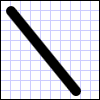
尽管 Line 类确实提供了 Fill 属性,但设置该属性不会有任何效果,因为 Line 没有区域。
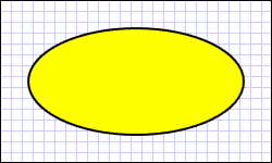
另一个常见形状是 Ellipse。 可通过定义形状的 Ellipse 和 Width 属性来创建 Height。 要绘制一个圆,请指定一个 Ellipse 和 Width 值相等的 Height。
<Ellipse
Fill="Yellow"
Height="100"
Width="200"
StrokeThickness="2"
Stroke="Black"/>
using System;
using System.Windows;
using System.Windows.Controls;
using System.Windows.Media;
using System.Windows.Shapes;

namespace SDKSample
{
    public partial class SetBackgroundColorOfShapeExample : Page
    {
        public SetBackgroundColorOfShapeExample()
        {
            // Create a StackPanel to contain the shape.
            StackPanel myStackPanel = new StackPanel();

            // Create a red Ellipse.
            Ellipse myEllipse = new Ellipse();

            // Create a SolidColorBrush with a red color to fill the
            // Ellipse with.
            SolidColorBrush mySolidColorBrush = new SolidColorBrush();

            // Describes the brush's color using RGB values.
            // Each value has a range of 0-255.
            mySolidColorBrush.Color = Color.FromArgb(255, 255, 255, 0);
            myEllipse.Fill = mySolidColorBrush;
            myEllipse.StrokeThickness = 2;
            myEllipse.Stroke = Brushes.Black;

            // Set the width and height of the Ellipse.
            myEllipse.Width = 200;
            myEllipse.Height = 100;

            // Add the Ellipse to the StackPanel.
            myStackPanel.Children.Add(myEllipse);

            this.Content = myStackPanel;
        }
    }
}
Imports System.Windows
Imports System.Windows.Controls
Imports System.Windows.Media
Imports System.Windows.Shapes

Namespace SDKSample
    Partial Public Class SetBackgroundColorOfShapeExample
        Inherits Page
        Public Sub New()
            ' Create a StackPanel to contain the shape.
            Dim myStackPanel As New StackPanel()

            ' Create a red Ellipse.
            Dim myEllipse As New Ellipse()

            ' Create a SolidColorBrush with a red color to fill the
            ' Ellipse with.
            Dim mySolidColorBrush As New SolidColorBrush()

            ' Describes the brush's color using RGB values.
            ' Each value has a range of 0-255.
            mySolidColorBrush.Color = Color.FromArgb(255, 255, 255, 0)
            myEllipse.Fill = mySolidColorBrush
            myEllipse.StrokeThickness = 2
            myEllipse.Stroke = Brushes.Black

            ' Set the width and height of the Ellipse.
            myEllipse.Width = 200
            myEllipse.Height = 100

            ' Add the Ellipse to the StackPanel.
            myStackPanel.Children.Add(myEllipse)

            Me.Content = myStackPanel
        End Sub

    End Class
End Namespace
下图显示了一个呈现的 Ellipse 示例。
使用路径和几何图形
Path 类可用于绘制曲线和复杂的形状。 这些曲线和形状使用 Geometry 对象进行描述。 要使用 Path,需要创建一个 Geometry 并使用它来设置 Path 对象的 Data 属性。
有多种 Geometry 对象可供选择。 LineGeometry、RectangleGeometry 和 EllipseGeometry 类描述相对简单的形状。 要创建更复杂的形状或创建曲线,请使用 PathGeometry。
PathGeometry and PathSegments
PathGeometry 对象由一个或多个 PathFigure 对象组成;每个 PathFigure 代表不同的“图形”或形状。 每个 PathFigure 本身由一个或多个 PathSegment 对象组成,每个对象代表图形或形状的连接部分。 细分类型包括:LineSegment、BezierSegment 和 ArcSegment。
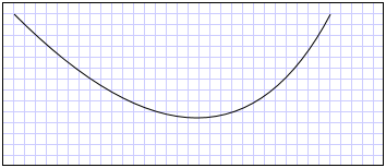
下面的示例使用了 Path 绘制二次贝塞尔曲线。
<Path Stroke="Black" StrokeThickness="1">
  <Path.Data>
    <PathGeometry>
      <PathGeometry.Figures>
        <PathFigureCollection>
          <PathFigure StartPoint="10,100">
            <PathFigure.Segments>
              <PathSegmentCollection>
                <QuadraticBezierSegment Point1="200,200" Point2="300,100" />
              </PathSegmentCollection>
            </PathFigure.Segments>
          </PathFigure>
        </PathFigureCollection>
      </PathGeometry.Figures>
    </PathGeometry>
  </Path.Data>
</Path>
下图显示了呈现的形状。
有关 PathGeometry 和其他 Geometry 类的更多信息,请参阅几何概述。
XAML 缩写语法
在 Extensible Application Markup Language (XAML) 中,还可使用特殊的缩写语法来描述 Path。 以下示例中,使用了缩写语法绘制复杂的形状。
      <Path Stroke="DarkGoldenRod" StrokeThickness="3"
Data="M 100,200 C 100,25 400,350 400,175 H 280" />
下图显示了呈现的 Path。
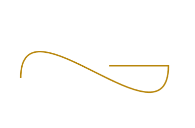
Data 属性字符串以“moveto”命令开头,用 M 表示,它为 Canvas 的坐标系统中的路径创建起点。 Path数据参数区分大小写。 大写字母 M 指示新的当前点的绝对位置。 小写字母 m 指示相对坐标。 第一段是一条三次贝塞尔曲线,该曲线以 (100,200) 开始,至 (400,175) 结束,使用 (100,25) 和 (400,350) 这两个控制点绘制。 这一段由 Data 属性字符串中的“C”命令指示。 同样,大写的 C 指示绝对路径;小写的 c 指示相对路径。
第二段以绝对水平“lineto”命令 H 开头,它指定绘制一条从前面的子路径的终点 (400,175) 到新终点 (280,175) 的直线。 由于它是一个水平“lineto”命令,因此指定的值是 x 坐标。
有关完整路径语法的详细信息,请参阅 引用和Data使用 PathGeometry 创建形状。
绘制形状
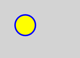
Brush 对象用于绘制形状的 Stroke 和 Fill。 在以下示例中,指定了 Ellipse 的笔划和填充。 注意画笔属性的有效输入可以是关键字或十六进制颜色值。 有关可用颜色关键字的详细信息,请参阅 Colors 命名空间中 System.Windows.Media 类的属性。
<Canvas Background="LightGray">
   <Ellipse
      Canvas.Top="50"
      Canvas.Left="50"
      Fill="#FFFFFF00"
      Height="75"
      Width="75"
      StrokeThickness="5"
      Stroke="#FF0000FF"/>
</Canvas>
下图显示了呈现的 Ellipse。
或者,可以使用属性元素语法显式创建 SolidColorBrush 对象,用纯色绘制形状。
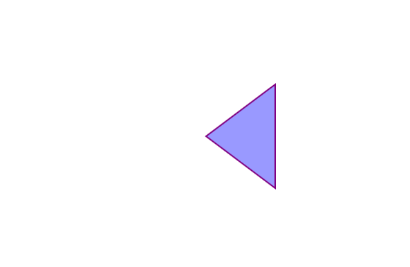
<!-- This polygon shape uses pre-defined color values for its Stroke and
     Fill properties.
     The SolidColorBrush's Opacity property affects the fill color in
     this case by making it slightly transparent (opacity of 0.4) so
     that it blends with any underlying color. -->

<Polygon
    Points="300,200 400,125 400,275 300,200"
    Stroke="Purple"
    StrokeThickness="2">
    <Polygon.Fill>
       <SolidColorBrush Color="Blue" Opacity="0.4"/>
    </Polygon.Fill>
</Polygon>
下图显示了呈现的形状。
还可以使用渐变、图像、模式等绘制形状的笔划或填充。 有关详细信息,请参阅使用纯色和渐变进行绘制概述。
可拉伸的形状
Line、Path、Polygon、Polyline 和 Rectangle 类都具有 Stretch 属性。 此属性确定如何拉伸 Shape 对象的内容(要绘制的形状)以填充 Shape 对象的布局空间。 由于 Shape 对象显式的 Shape 和 Width 设置,或者由于其 Height 和 HorizontalAlignment 设置,该对象的布局空间是由布局系统分配的 VerticalAlignment 的空间量。 有关 Windows Presentation Foundation 中的布局的其他信息,请参阅布局概述。
Stretch 属性采用下列值之一:
UniformToFill:拉伸 Shape 对象的内容以填满布局空间,同时保留原始纵横比。
请注意,拉伸 Shape 对象的内容时,会在拉伸后绘制 Shape 对象的轮廓。
在以下示例中,使用了 Polygon 来绘制从 (0,0) 到 (0,1) 再到 (1,1) 的一个很小的三角形。 Polygon 对象的 Width 和 Height 设置为 100,其拉伸属性设置为 Fill。 因此,Polygon 对象的内容(三角形)被拉伸以填充更大的空间。
<Polygon
  Points="0,0 0,1 1,1"
  Fill="Blue"
  Width="100"
  Height="100"
  Stretch="Fill"
  Stroke="Black"
  StrokeThickness="2" />
PointCollection myPointCollection = new PointCollection();
myPointCollection.Add(new Point(0,0));
myPointCollection.Add(new Point(0,1));
myPointCollection.Add(new Point(1,1));

Polygon myPolygon = new Polygon();
myPolygon.Points = myPointCollection;
myPolygon.Fill = Brushes.Blue;
myPolygon.Width = 100;
myPolygon.Height = 100;
myPolygon.Stretch = Stretch.Fill;
myPolygon.Stroke = Brushes.Black;
myPolygon.StrokeThickness = 2;
转换形状
Transform 类提供在二维平面中转换形状的方法。 不同类型的变换包括旋转 (RotateTransform)、缩放 (ScaleTransform)、倾斜 (SkewTransform) 和平移 (TranslateTransform)。
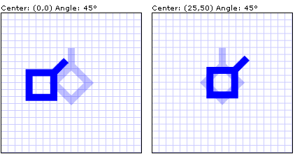
应用于形状的常见转换就是旋转。 要旋转图形,请创建 RotateTransform 并指定其 Angle。 45 度的 Angle 会顺时针将元素旋转 45 度;90 度角会将元素顺时针旋转 90 度等。 如果要控制元素旋转的点,请设置 CenterX 和 CenterY 属性。 这些属性值在被转换的元素的坐标空间中表示。 CenterX 和 CenterY 具有默认值 0。 最后,将 RotateTransform 应用于元素。 如果不希望变换影响到布局,请设置形状的 RenderTransform 属性。
在以下示例中,使用了 RotateTransform 围绕形状的左上角 (0,0) 将形状旋转 45 度。
<!-- Rotates the Polyline 45 degrees about the point (0,0). -->
<Polyline Points="25,25 0,50 25,75 50,50 25,25 25,0"
  Stroke="Blue" StrokeThickness="10"
  Canvas.Left="75" Canvas.Top="50">
  <Polyline.RenderTransform>
    <RotateTransform CenterX="0" CenterY="0" Angle="45" />
  </Polyline.RenderTransform>
</Polyline>
在以下示例中,另一个形状也旋转了 45 度,但这次它围绕点 (25,50) 旋转。
<!-- Rotates the Polyline 45 degrees about its center. -->
<Polyline
  Points="25,25 0,50 25,75 50,50 25,25 25,0"
  Stroke="Blue" StrokeThickness="10"
  Canvas.Left="75" Canvas.Top="50"
  RenderTransformOrigin="0.5,0.5">
  <Polyline.RenderTransform>
    <RotateTransform Angle="45" />
  </Polyline.RenderTransform>
</Polyline>
下图显示了应用两次转换的结果。
在前面的示例中,对每一个形状对象应用了一次转换。 若要对形状(或任何其他 UI 元素)应用多个转换,请使用 TransformGroup。
