3D 轉換概觀
本主題描述如何在 Windows Presentation Foundation (WPF) 圖形系統中將轉換套用至 3D 模型。 轉換可讓開發人員重新置放模型、調整模型大小,以及調整模型方向,而不需要變更定義模型的基底值。
3D 座標空間
Windows Presentation Foundation (WPF) 中的 3D 圖形內容會封裝在可以參與二維元素結構的 元素 Viewport3D 中。 圖形系統會將 Viewport3D 視為二維視覺元素,就像 Windows Presentation Foundation (WPF) 中的許多其他專案一樣。 Viewport3D 運作的方式就像視窗 (檢視區) 一樣,但是是在三維的場景。 更準確地說,這是投影 3D 場景的表面。 雖然您可以在相同的場景圖形中搭配其他 2D 繪圖物件使用 Viewport3D,但是您無法在 Viewport3D 內交錯 2D 和 3D 物件。 在以下討論中所描述的座標空間都包含在 Viewport3D 元素中。
2D 圖形的 Windows Presentation Foundation (WPF) 座標系統會找出轉譯介面左上角的原點(通常是螢幕)。 在 2D 系統中,正 X 軸值會往右繼續,而正 y 軸值會往下繼續。 不過,在 3D 座標系統中,原點位於螢幕中央,正 X 軸值會往右繼續,但正 y 軸值會往上移動,而正 Z 軸值會從原點向外向外向向,朝檢視者走去。
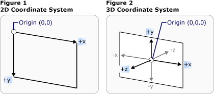
座標系統比較
這些座標軸所定義的空間是 Windows Presentation Foundation (WPF) 中 3D 物件的固定參考框架。 當您在此空間中建置模型,並建立光線和觀景窗來檢視這些模型時,有助於區分此靜態參考座標系 (或稱為「世界空間」) 與您為每個模型套用轉換時建立的當地參考座標系。 也請記住,在世界空間中的物件取決於光線和觀景窗設定,可能看起來完全不同,或者完全無法看見,但觀景窗的位置不會改變世界空間中物件的位置。
轉換模型
當您建立模型時,模型在場景中有特定的位置。 若要在場景中四處移動模型、旋轉模型,或變更模型的大小,變更定義模型的頂點本身並不實用。 相反地,就像在 2D 中一樣,您會將轉換套用至模型。
每個模型物件都有一個 Transform 屬性,您可以移動、重新置放或調整模型的大小。 當您套用轉換時,可以透過轉換所指定的任何向量或值,有效率地位移模型的所有點。 換句話說,您已經轉換定義模型所在的座標空間 (「模型空間」),但尚未變更在整個場景的座標系統 (「世界空間」) 中組成模型幾何的值。
平移轉換
3D 轉換繼承自抽象基類 Transform3D ;這些轉換包括 affine 轉換類別 TranslateTransform3D 、 ScaleTransform3D 和 RotateTransform3D 。 Windows Presentation Foundation (WPF) 3D 系統也提供類別 MatrixTransform3D ,可讓您在更精簡的矩陣作業中指定相同的轉換。
TranslateTransform3D 會以 OffsetX 、 OffsetY 和 OffsetZ 屬性指定之位移向量的方向移動 Model3D 中的所有點。 例如,(2,2,2) 有一個立方體的頂點,(0,1.6,1) 的位移向量會將該頂點 (2,2,2) 移動到 (2,3.6,3)。 立方體的頂點還是在模型空間中的 (2,2,2),但現在該模型空間已變更它與世界空間的關聯性,因此模型空間中的 (2,2,2) 就是世界空間中的 (2,3.6,3)。
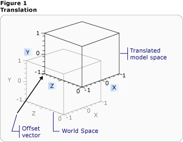
使用位移的平移
下列程式碼範例示範如何套用平移。
<Page xmlns="http://schemas.microsoft.com/winfx/2006/xaml/presentation"
  xmlns:x="http://schemas.microsoft.com/winfx/2006/xaml" >
  <DockPanel>
    <Viewbox>
      <Canvas Width="600" Height="201">

        <!-- The Viewport3D provides a rendering surface for 3-D visual content. -->
        <Viewport3D Name="MyAnimatedObject"
          ClipToBounds="True" Width="600" Height="150"
          Canvas.Left="0" Canvas.Top="10">

          <!-- Defines the camera used to view the 3D object. -->
          <Viewport3D.Camera>
            <PerspectiveCamera x:Name="myPerspectiveCamera" Position="0,0,2" LookDirection="0,0,-1"
             FieldOfView="60" />
          </Viewport3D.Camera>

          <!-- The ModelVisual3D children contain the 3D models -->
          <Viewport3D.Children>

            <!-- This ModelVisual3D defines the light cast in the scene. Without light, the
                 3D object cannot be seen. -->
            <ModelVisual3D>
              <ModelVisual3D.Content>
                <DirectionalLight Color="#FFFFFF" Direction="-0.612372,-0.5,-0.612372" />
              </ModelVisual3D.Content>
            </ModelVisual3D>
            <ModelVisual3D>
              <ModelVisual3D.Content>
                <GeometryModel3D>

                  <!-- The geometry specifes the shape of the 3D plane. In this case, a flat sheet is created. -->
                  <GeometryModel3D.Geometry>
                    <MeshGeometry3D
                     TriangleIndices="0,1,2 3,4,5 "
                     Normals="0,0,1 0,0,1 0,0,1 0,0,1 0,0,1 0,0,1 "
                     TextureCoordinates="0,0 1,0 1,1 1,1 0,1 0,0 "
                     Positions="-0.5,-0.5,0.5 0.5,-0.5,0.5 0.5,0.5,0.5 0.5,0.5,0.5 -0.5,0.5,0.5 -0.5,-0.5,0.5 " />
                  </GeometryModel3D.Geometry>

                  <!-- The material specifies the material applied to the plane. In this case it is a linear gradient.-->
                  <GeometryModel3D.Material>
                    <MaterialGroup>
                      <DiffuseMaterial>
                        <DiffuseMaterial.Brush>
                          <SolidColorBrush Color="Cyan" Opacity="0.3"/>
                        </DiffuseMaterial.Brush>
                      </DiffuseMaterial>
                    </MaterialGroup>
                  </GeometryModel3D.Material>
                  <!-- The Transform specifies how to transform the 3D object. The OffsetX property is animated
                       in the Storyboard below. -->
                  <GeometryModel3D.Transform>
                    <TranslateTransform3D x:Name="myTranslateTransform3D" OffsetX="0" OffsetY="0" OffsetZ="0" />
                  </GeometryModel3D.Transform>
                </GeometryModel3D>
              </ModelVisual3D.Content>
            </ModelVisual3D>
          </Viewport3D.Children>
          <!-- Trigger the TranslateTransform3D animation when the 3D object loads. -->
          <Viewport3D.Triggers>
            <EventTrigger RoutedEvent="Viewport3D.Loaded">
              <BeginStoryboard>
                <Storyboard>

                  <!-- This animation animates the OffsetX property of the TranslateTransform3D. -->
                  <DoubleAnimation
                   Storyboard.TargetName="myTranslateTransform3D"
                   Storyboard.TargetProperty="OffsetX"
                   To="-0.8"
                   AutoReverse="True" RepeatBehavior="Forever" />

                  <!-- If you want to animate OffsetY and/or OffsetZ, create similar DoubleAnimations
                       respectively. -->

                </Storyboard>
              </BeginStoryboard>
            </EventTrigger>
          </Viewport3D.Triggers>
        </Viewport3D>
      </Canvas>
    </Viewbox>
  </DockPanel>
</Page>
縮放轉換
ScaleTransform3D 會以參考中心點的指定尺規向量來變更模型的尺規。 指定統一的縮放比例,會將模型沿著 X、Y 和 Z 軸縮放相同的值,以便依比例變更模型的大小。 例如,將轉換的 ScaleX 、 ScaleY 和 ScaleZ 屬性設定為 0.5 會減半模型的大小;將相同的屬性設定為 2 會將其小數位數加倍于這三個座標軸。
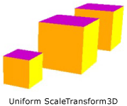
ScaleVector 範例
指定不一致的縮放變換 (X、 Y 和 Z 值並非全都相同的縮放變換),您可以讓模型在一或兩個維度伸長或收縮,而不影響其他維度。 例如,將 設定 ScaleX 為 1、 ScaleY 設為 2 和 ScaleZ 1 會導致轉換後的模型高度加倍,但沿著 X 和 Z 軸保持不變。
ScaleTransform3D 預設會讓頂點相對於原點 (0,0,0) 展開或收縮。 不過,如果您想要轉換的模型不會從原點繪製,則從原點調整模型不會「就地」調整模型。相反地,當模型的頂點乘以小數位數向量時,縮放作業將會有轉譯模型以及調整模型的效果。
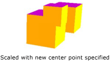
縮放中心範例
若要「就地」調整模型,請藉由設定 ScaleTransform3D 的 CenterX 、 CenterY 和 CenterZ 屬性來指定模型的中心。 這可確保圖形系統調整模型空間,然後將它轉譯成置中位於指定的 Point3D 上。 但是如果您已經先根據原點建置模型,再指定不同的中心點,則會看到模型偏離原點。
旋轉轉換
您可以透過數種不同的方式,以 3D 旋轉模型。 一般旋轉轉換是指定一個軸,以及繞著該軸旋轉的角度。 類別 RotateTransform3D 可讓您使用其 Rotation 屬性來定義 Rotation3D 。 接著,您可以在 Rotation3D 上指定 Axis 和 Angle 屬性,在此案例中為 AxisAngleRotation3D ,以定義轉換。 下列範例會將模型繞著 Y 軸旋轉 60 度。
<Page xmlns="http://schemas.microsoft.com/winfx/2006/xaml/presentation"
  xmlns:x="http://schemas.microsoft.com/winfx/2006/xaml" >
  <DockPanel>
    <Viewbox>
      <Canvas Width="321" Height="201">

        <!-- The Viewport3D provides a rendering surface for 3-D visual content. -->
        <Viewport3D Name="MyAnimatedObject"
          ClipToBounds="True" Width="150" Height="150"
          Canvas.Left="0" Canvas.Top="10">

          <!-- Defines the camera used to view the 3D object. -->
          <Viewport3D.Camera>
            <PerspectiveCamera x:Name="myPerspectiveCamera" Position="0,0,2" LookDirection="0,0,-1"
             FieldOfView="60" />
          </Viewport3D.Camera>

          <!-- The ModelVisual3D children contain the 3D models -->
          <Viewport3D.Children>

            <!-- Two ModelVisual3D define the lights cast in the scene. Without light, the
                 3D object cannot be seen. Also, the direction of the lights affect shadowing. -->
            <ModelVisual3D>
              <ModelVisual3D.Content>
                <DirectionalLight Color="#FFFFFF" Direction="-0.612372,-0.5,-0.612372" />
              </ModelVisual3D.Content>
            </ModelVisual3D>
            <ModelVisual3D>
              <ModelVisual3D.Content>
                <DirectionalLight Color="#FFFFFF" Direction="0.612372,-0.5,-0.612372" />
              </ModelVisual3D.Content>
            </ModelVisual3D>
            <ModelVisual3D>
              <ModelVisual3D.Content>
                <GeometryModel3D>

                  <!-- The geometry specifes the shape of the 3D plane. In this case, a flat sheet is created. -->
                  <GeometryModel3D.Geometry>
                    <MeshGeometry3D
                     TriangleIndices="0,1,2 3,4,5 "
                     Normals="0,0,1 0,0,1 0,0,1 0,0,1 0,0,1 0,0,1 "
                     TextureCoordinates="0,0 1,0 1,1 1,1 0,1 0,0 "
                     Positions="-0.5,-0.5,0.5 0.5,-0.5,0.5 0.5,0.5,0.5 0.5,0.5,0.5 -0.5,0.5,0.5 -0.5,-0.5,0.5 " />
                  </GeometryModel3D.Geometry>

                  <!-- The material specifies the material applied to the plane. In this case it is a linear gradient.-->
                  <GeometryModel3D.Material>
                    <MaterialGroup>
                      <DiffuseMaterial>
                        <DiffuseMaterial.Brush>
                          <LinearGradientBrush StartPoint="0,0.5" EndPoint="1,0.5">
                            <LinearGradientBrush.GradientStops>
                              <GradientStop Color="Yellow" Offset="0" />
                              <GradientStop Color="Red" Offset="0.25" />
                              <GradientStop Color="Blue" Offset="0.75" />
                              <GradientStop Color="LimeGreen" Offset="1" />
                            </LinearGradientBrush.GradientStops>
                          </LinearGradientBrush>
                        </DiffuseMaterial.Brush>
                      </DiffuseMaterial>
                    </MaterialGroup>
                  </GeometryModel3D.Material>

                  <!-- The Transform specifies how to transform the 3D object. The properties of the
                        Rotation object are animated causing the 3D object to rotate and "wobble" (see Storyboard below).-->
                  <GeometryModel3D.Transform>
                    <RotateTransform3D>
                      <RotateTransform3D.Rotation>
                        <AxisAngleRotation3D x:Name="myAngleRotation" Axis="0,3,0" Angle="40" />
                      </RotateTransform3D.Rotation>
                    </RotateTransform3D>
                  </GeometryModel3D.Transform>
                </GeometryModel3D>
              </ModelVisual3D.Content>
            </ModelVisual3D>
          </Viewport3D.Children>

          <!-- Trigger the rotation animation when the 3D object loads. -->
          <Viewport3D.Triggers>
            <EventTrigger RoutedEvent="Viewport3D.Loaded">
              <BeginStoryboard>
                <Storyboard>

                  <!-- This animation animates the Angle property of the AxisAngleRotation3D
                       making the 3D object rotate from -60 degrees to 60 degrees. -->
                  <DoubleAnimation
                   Storyboard.TargetName="myAngleRotation"
                   Storyboard.TargetProperty="Angle"
                   From="-60" To="60" Duration="0:0:4" AutoReverse="True"  RepeatBehavior="Forever"/>

                  <!-- This animation animates the Axis property of the AxisAngleRotation3D
                       making the 3D wobble as it rotates. -->
                  <Vector3DAnimation
                   Storyboard.TargetName="myAngleRotation"
                   Storyboard.TargetProperty="Axis"
                   From="0,3,0" To="1,0,1" Duration="0:0:4" AutoReverse="True"  RepeatBehavior="Forever"/>

                </Storyboard>
              </BeginStoryboard>
            </EventTrigger>
          </Viewport3D.Triggers>
        </Viewport3D>
      </Canvas>

    </Viewbox>
  </DockPanel>
</Page>
注意:Windows Presentation Foundation (WPF) 3D 是右手系統,這表示旋轉的正角度值會導致軸的逆時針旋轉。
如果 RotateTransform3D 上的 、 CenterY 和 CenterZ 屬性未指定 CenterX 值,軸角度旋轉就會假設原點的旋轉。 若使用縮放比例,最好記住旋轉會轉換模型的整個座標空間。 如果模型不是相對於原點建立,或先前已平移,則可能會「以原點為中心」旋轉而不是就地旋轉。
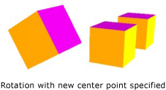
以指定的新中心進行的旋轉
若要「就地」旋轉模型,請指定模型真正的中心做為旋轉的中心。 因為幾何通常是以原點開始建立,所以您可以先調整模型的大小 (縮放模型),然後設定模型的方向 (旋轉模型),最後將模型移到想要的位置 (平移模型),通常都能在一組轉換之後得到預期的結果。
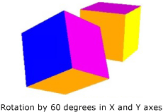
旋轉範例
軸角度旋轉適用於靜態轉換和一些動畫。 不過,如果考慮讓立方體模型繞著 X 軸旋轉 60 度,然後繞著 Z 軸旋轉 45 度。 您可以將這個轉換描述為兩個不連續的仿射轉換,或描述為矩陣。 不過,要順利以動畫顯示此種方式定義的旋轉很困難。 雖然以兩種方法計算的模型開始位置和結束位置都相同,但是模型所採取的中間位置則是具有計算不確定性。 四元數是一種用來計算旋轉開始和結束之間插補的替代方法。
四元數代表 3D 空間中的座標軸,以及繞該軸旋轉。 例如,某個四元數可能代表 (1,1,2) 軸和 50 度的旋轉。 四元數在定義旋轉的威力在於您可以對四元數執行兩個操作︰合成和插補。 套用至幾何的兩個四元陣列合表示「將幾何繞軸旋轉 2 by rotation2,然後將幾何繞軸旋轉 1 by rotation1」。藉由使用組合,您可以結合幾何上的兩個旋轉,以取得代表結果的單一四元數。 因為四元數插補可以計算兩個軸與方向之間的平滑合理路徑,所以可以在原始的四元數與合成的四元數之間進行插補,以達到兩個四元數之間的平滑轉換,讓您以動畫顯示轉換。 針對您想要建立動畫效果的模型,您可以使用 屬性的 來指定旋轉 QuaternionRotation3D 的 Rotation 目的地 Quaternion 。
使用轉換集合
建立場景時,常會對模型套用多個轉換。 將轉換新增至 Children 類別的 Transform3DGroup 集合,以方便將轉換分組,以套用至場景中的各種模型。 重複使用多個不同群組中的轉換通常很方便,因此您可以對每個執行個體套用一組不同的轉換來重複使用模型。 請注意,在集合中新增轉換的順序非常重要︰集合中的轉換會從第一個套用至最後一個。
以動畫顯示轉換
Windows Presentation Foundation (WPF) 3D 實作會參與與 2D 圖形相同的計時和動畫系統。 換句話說,若要建立 3D 場景的動畫效果,請以動畫顯示其模型的屬性。 您可以直接以動畫顯示基元的屬性,但是以動畫顯示變更模型位置或外觀的轉換通常更容易。 因為轉換可以套用至物件和個別模型,所以可以將一組動畫套用至 Model3DGroup Model3D 群組的子系,並將另一組動畫套用至一組物件。 如需 Windows Presentation Foundation (WPF) 計時和動畫系統的背景資訊,請參閱 動畫概觀 和 分鏡腳本概觀 。
若要在 Windows Presentation Foundation 中建立物件動畫,請建立時間軸、定義動畫(這在一段時間內確實是某些屬性值的變更),並指定要套用動畫的屬性。 這個屬性必須是 FrameworkElement 的屬性。 由於 3D 場景中的所有物件都是 Viewport3D 的子系,因此您想要套用至場景的任何動畫所設定的屬性都是 Viewport3D 的屬性。 請務必小心處理動畫的屬性路徑,因為語法可能很冗長。
假設您想要就地旋轉物件,但是也想要套用擺動運動,讓物件更多部分供人檢視。 您可以選擇對模型套用 RotateTransform3D,然後讓其旋轉軸從一個向量到另一個向量以動畫顯示。 下列程式碼範例示範如何將 Vector3DAnimation 套用至轉換 Rotation3D 的 Axis 屬性,假設 RotateTransform3D 是套 TransformGroup 用至具有 之模型的數個轉換之一。
//Define a rotation
RotateTransform3D myRotateTransform = new RotateTransform3D(new AxisAngleRotation3D(new Vector3D(0, 1, 0), 1));
'Define a rotation
Dim myRotateTransform As New RotateTransform3D(New AxisAngleRotation3D(New Vector3D(0, 1, 0), 1))
Vector3DAnimation myVectorAnimation = new Vector3DAnimation(new Vector3D(-1, -1, -1), new Duration(TimeSpan.FromMilliseconds(5000)));
myVectorAnimation.RepeatBehavior = RepeatBehavior.Forever;
Dim myVectorAnimation As New Vector3DAnimation(New Vector3D(-1, -1, -1), New Duration(TimeSpan.FromMilliseconds(5000)))
myVectorAnimation.RepeatBehavior = RepeatBehavior.Forever
您可以針對其他轉換屬性使用類似的語法來移動或縮放物件。 例如,您可以將 套用 Point3DAnimation 至縮放轉換上的 ScaleCenter 屬性,讓模型順暢地扭曲其圖形。
雖然上述範例會轉換 的屬性 GeometryModel3D ,但您也可以轉換場景中其他模型的屬性。 例如以動畫顯示套用至 Light 物件的平移,您可以建立能大幅變更模型外觀的移動光線和陰影效果。
因為觀景窗也是模型,所以同樣可以轉換觀景窗屬性。 雖然您可以轉換觀景窗位置或平面距離來變更場景的外觀 (實際上是轉換整個場景投影),但請注意,以這種方式達成的許多效果就觀者的「視覺感受」來說,會比對場景中的模型位置套用轉換來得少。
另請參閱
意見反應
即將登場:在 2024 年,我們將逐步淘汰 GitHub 問題作為內容的意見反應機制,並將它取代為新的意見反應系統。 如需詳細資訊,請參閱:https://aka.ms/ContentUserFeedback。
提交並檢視相關的意見反應
