幾何概觀
本概觀描述如何使用 Windows Presentation Foundation (WPF) Geometry 類別來描述圖形。 本主題也會對比物件和 Shape 元素之間的差異 Geometry 。
什麼是幾何?
衍生 Geometry 自它的類別和類別,例如 EllipseGeometry 、 PathGeometry 和 CombinedGeometry ,可讓您描述 2D 圖形的幾何。 這些幾何描繪有許多用途,像是定義圖形來繪製到螢幕或定義點擊測試和裁剪區域。 您甚至可以使用幾何來定義動畫路徑。
Geometry 物件可以是簡單物件,例如矩形和圓形,或從兩個或多個幾何物件建立的綜合物件。 您可以使用 和 StreamGeometry 類別來建立 PathGeometry 更複雜的幾何,讓您能夠描述弧線和曲線。
Geometry因為 是 的 Freezable 型別, Geometry 所以 物件提供數個特殊功能:它們可以宣告為 資源 、在多個物件之間共用、進行唯讀以改善效能、複製,以及讓執行緒安全。 如需物件所提供 Freezable 之不同功能的詳細資訊,請參閱 Freezable 物件概觀 。
幾何與圖形
和 GeometryShape 類別看起來很類似,因為它們都描述 2D 圖形(例如 比較 EllipseGeometry 和 Ellipse ),但有一個重要的差異。
一是類別 Geometry 繼承自 Freezable 類別, Shape 而 類別則繼承自 FrameworkElement 。 因為它們是元素, Shape 所以物件可以自行轉譯並參與版面配置系統,而 Geometry 物件則不能。
雖然 Shape 物件比 Geometry 物件更容易使用, Geometry 但物件比較多用途。 Shape雖然物件用來轉譯 2D 圖形, Geometry 但物件可用來定義 2D 圖形的幾何區域、定義裁剪的區域,或定義區域以進行點擊測試,例如。
路徑圖形
一個 Shape 是 類別 Path ,實際上會使用 Geometry 來描述其內容。 藉由使用 設定 Data 的 屬性 Path 並設定其 Fill 和 Stroke 屬性,即可轉譯 Geometry 。 Geometry
採用幾何的通用屬性
如前幾節所述,Geometry 物件可以與其他物件一起用於許多用途,例如繪製圖形、動畫以及裁剪。 下表列出數個 Geometry 類別,這些類別具有接受 物件的屬性。
| 類型 | 屬性 |
|---|---|
| DoubleAnimationUsingPath | PathGeometry |
| DrawingGroup | ClipGeometry |
| GeometryDrawing | Geometry |
| Path | Data |
| UIElement | Clip |
簡單幾何類型
所有幾何的基類都是抽象類別 Geometry 。 衍生自 類別的 Geometry 類別大致可以分成三個類別:簡單幾何、路徑幾何和複合幾何。
簡單的幾何類別包括 LineGeometry 、 RectangleGeometry 和 EllipseGeometry ,可用來建立基本的幾何圖形,例如線條、矩形和圓形。
LineGeometry藉由指定線條的起點和終點來定義 。
RectangleGeometry使用 結構來定義 Rect ,其會指定其相對位置和高度和寬度。 您可以藉由設定 RadiusX 和 RadiusY 屬性來建立圓角矩形。
EllipseGeometry是由中心點、x 半徑和 y 半徑所定義。 下列範例示範如何建立簡單的幾何以用於轉譯和裁剪。
這些相同的圖形,以及更複雜的圖形,可以使用 或 將幾何物件結合在一 PathGeometry 起來建立,但這些類別提供更簡單的方法來產生這些基本幾何圖形。
下列範例示範如何建立和轉譯 LineGeometry 。 如先前所述, Geometry 物件無法繪製本身,因此範例會使用 Path 圖形來轉譯線條。 因為線條沒有區域,因此設定 Fill 的 Path 屬性不會有任何作用;相反地,只會 Stroke 指定 和 StrokeThickness 屬性。 下圖顯示範例的輸出。
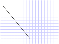
從 (10,20) 繪製到 (100,130) 的 LineGeometry
<Path Stroke="Black" StrokeThickness="1" >
  <Path.Data>
    <LineGeometry StartPoint="10,20" EndPoint="100,130" />
  </Path.Data>
</Path>
LineGeometry myLineGeometry = new LineGeometry();
myLineGeometry.StartPoint = new Point(10,20);
myLineGeometry.EndPoint = new Point(100,130);

Path myPath = new Path();
myPath.Stroke = Brushes.Black;
myPath.StrokeThickness = 1;
myPath.Data = myLineGeometry;
Dim myLineGeometry As New LineGeometry()
myLineGeometry.StartPoint = New Point(10,20)
myLineGeometry.EndPoint = New Point(100,130)

Dim myPath As New Path()
myPath.Stroke = Brushes.Black
myPath.StrokeThickness = 1
myPath.Data = myLineGeometry
下一個範例示範如何建立和轉譯 EllipseGeometry 。 範例會將 CenterEllipseGeometry 的 設定為 點 50,50 ,而 x 半徑和 y 半徑都設定為 50 ,這會建立直徑為 100 的圓形。 省略號的內部是藉由將值指派給 Path 元素的 Fill 屬性來繪製,在此案例中為 Gold 。 下圖顯示範例的輸出。
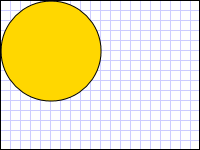
在 (50,50) 繪製的 EllipseGeometry
<Path Fill="Gold" Stroke="Black" StrokeThickness="1">
  <Path.Data>
    <EllipseGeometry Center="50,50" RadiusX="50" RadiusY="50" />
  </Path.Data>
</Path>
EllipseGeometry myEllipseGeometry = new EllipseGeometry();
myEllipseGeometry.Center = new Point(50, 50);
myEllipseGeometry.RadiusX = 50;
myEllipseGeometry.RadiusY = 50;

Path myPath = new Path();
myPath.Fill = Brushes.Gold;
myPath.Stroke = Brushes.Black;
myPath.StrokeThickness = 1;
myPath.Data = myEllipseGeometry;
Dim myEllipseGeometry As New EllipseGeometry()
myEllipseGeometry.Center = New Point(50, 50)
myEllipseGeometry.RadiusX = 50
myEllipseGeometry.RadiusY = 50

Dim myPath As New Path()
myPath.Fill = Brushes.Gold
myPath.Stroke = Brushes.Black
myPath.StrokeThickness = 1
myPath.Data = myEllipseGeometry
下列範例示範如何建立和轉譯 RectangleGeometry 。 矩形的位置和維度是由 Rect 結構所定義。 這個位置是50,50,而高度和寬度都是 25,可建立一個正方形。 下圖顯示範例的輸出。
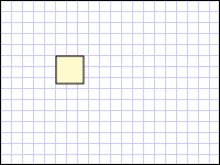
在 50,50 繪製的 RectangleGeometry
<Path Fill="LemonChiffon" Stroke="Black" StrokeThickness="1">
  <Path.Data>
    <RectangleGeometry Rect="50,50,25,25" />
  </Path.Data>
</Path>
RectangleGeometry myRectangleGeometry = new RectangleGeometry();
myRectangleGeometry.Rect = new Rect(50,50,25,25);

Path myPath = new Path();
myPath.Fill = Brushes.LemonChiffon;
myPath.Stroke = Brushes.Black;
myPath.StrokeThickness = 1;
myPath.Data = myRectangleGeometry;
Dim myRectangleGeometry As New RectangleGeometry()
myRectangleGeometry.Rect = New Rect(50,50,25,25)

Dim myPath As New Path()
myPath.Fill = Brushes.LemonChiffon
myPath.Stroke = Brushes.Black
myPath.StrokeThickness = 1
myPath.Data = myRectangleGeometry
下列範例示範如何使用 作為 EllipseGeometry 影像的剪輯區域。 物件 Image 是以 200 和 Height 150 的 來定義 Width 。 EllipseGeometryRadiusX 值為 100 的 , RadiusY 值為 75,而 Center 值為 100,75 則設定為 Clip 影像的 屬性。 只有橢圓形區域內的影像部分才會顯示。 下圖顯示範例的輸出。
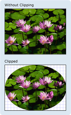
用來裁剪影像控制項的 EllipseGeometry
<Image
  Source="sampleImages\Waterlilies.jpg"
  Width="200" Height="150" HorizontalAlignment="Left">
  <Image.Clip>
    <EllipseGeometry
      RadiusX="100"
      RadiusY="75"
      Center="100,75"/>
  </Image.Clip>
</Image>
// Create the image to clip.
Image myImage = new Image();
Uri imageUri =
    new Uri(@"C:\\Documents and Settings\\All Users\\Documents\My Pictures\\Sample Pictures\\Water lilies.jpg", UriKind.Relative);
myImage.Source = new BitmapImage(imageUri);
myImage.Width = 200;
myImage.Height = 150;
myImage.HorizontalAlignment = HorizontalAlignment.Left;

// Use an EllipseGeometry to define the clip region.
EllipseGeometry myEllipseGeometry = new EllipseGeometry();
myEllipseGeometry.Center = new Point(100, 75);
myEllipseGeometry.RadiusX = 100;
myEllipseGeometry.RadiusY = 75;
myImage.Clip = myEllipseGeometry;
' Create the image to clip.
Dim myImage As New Image()
Dim imageUri As New Uri("C:\\Documents and Settings\\All Users\\Documents\My Pictures\\Sample Pictures\\Water lilies.jpg", UriKind.Relative)
myImage.Source = New BitmapImage(imageUri)
myImage.Width = 200
myImage.Height = 150
myImage.HorizontalAlignment = HorizontalAlignment.Left

' Use an EllipseGeometry to define the clip region.
Dim myEllipseGeometry As New EllipseGeometry()
myEllipseGeometry.Center = New Point(100, 75)
myEllipseGeometry.RadiusX = 100
myEllipseGeometry.RadiusY = 75
myImage.Clip = myEllipseGeometry
路徑幾何
類別 PathGeometry 及其輕量型對等 StreamGeometry 的 類別提供方法來描述由弧線、曲線和線條組成的多個複雜數位。
的核心 PathGeometry 是 物件的集合 PathFigure ,因此命名為 ,因為每個圖形都會描述 中的 PathGeometry 離散圖形。 每個 PathFigure 本身是由一或多個 PathSegment 物件所組成,每個物件都會描述圖形的區段。
區段的類型繁多。
| 區段類型 | 描述 | 範例 |
|---|---|---|
| ArcSegment | 在兩個點之間建立橢圓形弧線。 | 建立橢圓形弧線。 |
| BezierSegment | 在兩個點之間建立三次方貝茲曲線。 | 建立三次方貝茲曲線。 |
| LineSegment | 在兩個點之間建立線條。 | 在 PathGeometry 中建立 LineSegment |
| PolyBezierSegment | 建立一系列三次方貝茲曲線。 | PolyBezierSegment請參閱類型頁面。 |
| PolyLineSegment | 建立一系列的線條。 | PolyLineSegment請參閱類型頁面。 |
| PolyQuadraticBezierSegment | 建立一系列二次方貝茲曲線。 | PolyQuadraticBezierSegment請參閱頁面。 |
| QuadraticBezierSegment | 建立二次方貝茲曲線。 | 建立二次方貝茲曲線。 |
內的 PathFigure 區段會合並成單一幾何圖形,而每個區段的終點都是下一個線段的起點。 的 StartPointPathFigure 屬性會指定繪製第一個線段的點。 每個後續區段都會從前一個區段的結束點開始。 例如,將 屬性設定 StartPoint 為 ,並使用 的 屬性設定 10,150 來建立 LineSegmentPoint ,即可定義從 10,50 到 10,150 的垂直 10,50 線。
下列範例會建立由 單 PathFigure 一所組成的簡單 PathGeometry , LineSegment 並使用 專案加以顯示 Path 。 物件的 PathFigureStartPoint 會設定為 10,20 ,而 LineSegment 會以 的 100,130 結束點定義 。 下圖顯示 PathGeometry 此範例所建立的 。

包含單一 LineSegment 的 PathGeometry
<Path Stroke="Black" StrokeThickness="1">
  <Path.Data>
    <PathGeometry>
      <PathGeometry.Figures>
        <PathFigure StartPoint="10,20">
          <PathFigure.Segments>
            <LineSegment Point="100,130"/>
          </PathFigure.Segments>
        </PathFigure>
      </PathGeometry.Figures>
    </PathGeometry>
  </Path.Data>
</Path>
// Create a figure that describes a
// line from (10,20) to (100,130).
PathFigure myPathFigure = new PathFigure();
myPathFigure.StartPoint = new Point(10,20);
myPathFigure.Segments.Add(
    new LineSegment(new Point(100,130),
    true /* IsStroked */ ));

/// Create a PathGeometry to contain the figure.
PathGeometry myPathGeometry = new PathGeometry();
myPathGeometry.Figures.Add(myPathFigure);

// Display the PathGeometry.
Path myPath = new Path();
myPath.Stroke = Brushes.Black;
myPath.StrokeThickness = 1;
myPath.Data = myPathGeometry;
' Create a figure that describes a
' line from (10,20) to (100,130).
Dim myPathFigure As New PathFigure()
myPathFigure.StartPoint = New Point(10,20)
myPathFigure.Segments.Add(New LineSegment(New Point(100,130), True)) ' IsStroked

''' Create a PathGeometry to contain the figure.
Dim myPathGeometry As New PathGeometry()
myPathGeometry.Figures.Add(myPathFigure)

' Display the PathGeometry.
Dim myPath As New Path()
myPath.Stroke = Brushes.Black
myPath.StrokeThickness = 1
myPath.Data = myPathGeometry
值得將此範例與上述 LineGeometry 範例進行對比。 用於 的 PathGeometry 語法比用於簡單 LineGeometry 更詳細的語法,在此情況下使用 LineGeometry 類別可能更有意義,但 的詳細資訊語法 PathGeometry 允許極其複雜且複雜的幾何區域。
您可以使用 物件的組合 PathSegment 來建立更複雜的幾何。
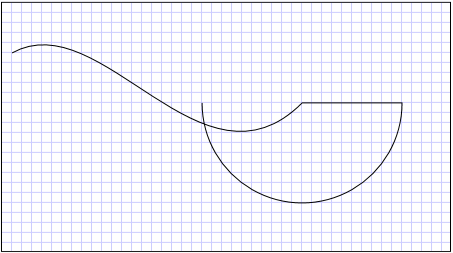
下一個 BezierSegment 範例會使用 、、 LineSegment 和 ArcSegment 來建立圖形。 此範例會先建立三次方貝茲曲線,其方式是定義四個點:起點,也就是上一段的終點、終點( Point3 ),以及兩個控制點( Point1 和 Point2 )。 三次方貝茲曲線的兩個控制點作用類似磁鐵,吸引原本為直線的部分,產生曲線。 第一個控制點 Point1 會影響曲線的開頭部分;第二個控制點 Point2 會影響曲線的結束部分。
接著,此範例會加入 LineSegment ,其繪製于前面 BezierSegment 前面其結束點到其 LineSegment 屬性所指定的點之間。
然後,此範例會將 ArcSegment 從前 LineSegment 一個端點繪製到其 Point 屬性所指定之點的 。 此範例也會指定弧線的 x 和 y 半徑 ()、旋轉角度 ( SizeRotationAngle )、指出所產生弧線角度的大小旗標 ( IsLargeArc ),以及指出弧線繪製方向的值( SweepDirection )。 下圖顯示此範例所建立的圖形。
PathGeometry
<Path Stroke="Black" StrokeThickness="1" >
  <Path.Data>
    <PathGeometry>
      <PathGeometry.Figures>
        <PathFigure StartPoint="10,50">
          <PathFigure.Segments>
            <BezierSegment
              Point1="100,0"
              Point2="200,200"
              Point3="300,100"/>
            <LineSegment Point="400,100" />
            <ArcSegment
              Size="50,50" RotationAngle="45"
              IsLargeArc="True" SweepDirection="Clockwise"
              Point="200,100"/>
          </PathFigure.Segments>
        </PathFigure>
      </PathGeometry.Figures>
    </PathGeometry>
  </Path.Data>
</Path>
// Create a figure.
PathFigure myPathFigure = new PathFigure();
myPathFigure.StartPoint = new Point(10,50);
myPathFigure.Segments.Add(
    new BezierSegment(
        new Point(100,0),
        new Point(200,200),
        new Point(300,100),
        true /* IsStroked */  ));
myPathFigure.Segments.Add(
    new LineSegment(
        new Point(400,100),
        true /* IsStroked */ ));
myPathFigure.Segments.Add(
    new ArcSegment(
        new Point(200,100),
        new Size(50,50),
        45,
        true, /* IsLargeArc */
        SweepDirection.Clockwise,
        true /* IsStroked */ ));

/// Create a PathGeometry to contain the figure.
PathGeometry myPathGeometry = new PathGeometry();
myPathGeometry.Figures.Add(myPathFigure);

// Display the PathGeometry.
Path myPath = new Path();
myPath.Stroke = Brushes.Black;
myPath.StrokeThickness = 1;
myPath.Data = myPathGeometry;
' Create a figure.
Dim myPathFigure As New PathFigure()
myPathFigure.StartPoint = New Point(10,50)
myPathFigure.Segments.Add(New BezierSegment(New Point(100,0), New Point(200,200), New Point(300,100), True)) ' IsStroked
myPathFigure.Segments.Add(New LineSegment(New Point(400,100), True)) ' IsStroked
myPathFigure.Segments.Add(New ArcSegment(New Point(200,100), New Size(50,50), 45, True, SweepDirection.Clockwise, True)) ' IsStroked  -  IsLargeArc

''' Create a PathGeometry to contain the figure.
Dim myPathGeometry As New PathGeometry()
myPathGeometry.Figures.Add(myPathFigure)

' Display the PathGeometry.
Dim myPath As New Path()
myPath.Stroke = Brushes.Black
myPath.StrokeThickness = 1
myPath.Data = myPathGeometry
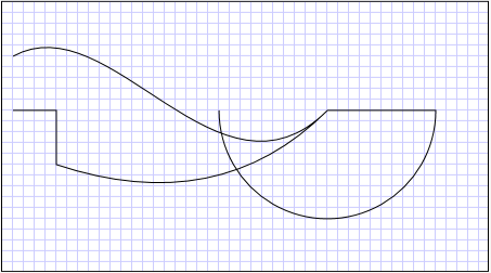
使用 內的 PathGeometry 多個 PathFigure 物件,即可建立更複雜的幾何。
下列範例會建立 具有兩 PathFigure 個 PathGeometry 物件的 ,每個物件都包含多個 PathSegment 物件。 PathFigure使用上述範例中的 ,以及 PathFigure 具有 PolyLineSegment 和 的 QuadraticBezierSegment 。 PolyLineSegment是使用點陣列來定義 ,而 QuadraticBezierSegment 是使用控制點和結束點來定義。 下圖顯示此範例所建立的圖形。
有多個圖形的 PathGeometry
<Path Stroke="Black" StrokeThickness="1" >
  <Path.Data>
    <PathGeometry>
      <PathGeometry.Figures>
        <PathFigure StartPoint="10,50">
          <PathFigure.Segments>
            <BezierSegment
              Point1="100,0"
              Point2="200,200"
              Point3="300,100"/>
            <LineSegment Point="400,100" />
            <ArcSegment
              Size="50,50" RotationAngle="45"
              IsLargeArc="True" SweepDirection="Clockwise"
              Point="200,100"/>
          </PathFigure.Segments>
        </PathFigure>

        <PathFigure StartPoint="10,100">
          <PathFigure.Segments>
            <PolyLineSegment Points="50,100 50,150" />
            <QuadraticBezierSegment Point1="200,200" Point2="300,100"/>
          </PathFigure.Segments>
        </PathFigure>
      </PathGeometry.Figures>
    </PathGeometry>
  </Path.Data>
</Path>
PathGeometry myPathGeometry = new PathGeometry();

// Create a figure.
PathFigure pathFigure1 = new PathFigure();
pathFigure1.StartPoint = new Point(10,50);
pathFigure1.Segments.Add(
    new BezierSegment(
        new Point(100,0),
        new Point(200,200),
        new Point(300,100),
        true /* IsStroked */ ));
pathFigure1.Segments.Add(
    new LineSegment(
        new Point(400,100),
        true /* IsStroked */ ));
pathFigure1.Segments.Add(
    new ArcSegment(
        new Point(200,100),
        new Size(50,50),
        45,
        true, /* IsLargeArc */
        SweepDirection.Clockwise,
        true /* IsStroked */ ));
myPathGeometry.Figures.Add(pathFigure1);

// Create another figure.
PathFigure pathFigure2 = new PathFigure();
pathFigure2.StartPoint = new Point(10,100);
Point[] polyLinePointArray =
    new Point[]{ new Point(50, 100), new Point(50, 150)};
PolyLineSegment myPolyLineSegment = new PolyLineSegment();
myPolyLineSegment.Points =
    new PointCollection(polyLinePointArray);
pathFigure2.Segments.Add(myPolyLineSegment);
pathFigure2.Segments.Add(
    new QuadraticBezierSegment(
        new Point(200,200),
        new Point(300,100),
        true /* IsStroked */ ));
myPathGeometry.Figures.Add(pathFigure2);

// Display the PathGeometry.
Path myPath = new Path();
myPath.Stroke = Brushes.Black;
myPath.StrokeThickness = 1;
myPath.Data = myPathGeometry;
Dim myPathGeometry As New PathGeometry()

' Create a figure.
Dim pathFigure1 As New PathFigure()
pathFigure1.StartPoint = New Point(10,50)
pathFigure1.Segments.Add(New BezierSegment(New Point(100,0), New Point(200,200), New Point(300,100), True)) ' IsStroked
pathFigure1.Segments.Add(New LineSegment(New Point(400,100), True)) ' IsStroked
pathFigure1.Segments.Add(New ArcSegment(New Point(200,100), New Size(50,50), 45, True, SweepDirection.Clockwise, True)) ' IsStroked  -  IsLargeArc
myPathGeometry.Figures.Add(pathFigure1)

' Create another figure.
Dim pathFigure2 As New PathFigure()
pathFigure2.StartPoint = New Point(10,100)
Dim polyLinePointArray() As Point = { New Point(50, 100), New Point(50, 150)}
Dim myPolyLineSegment As New PolyLineSegment()
myPolyLineSegment.Points = New PointCollection(polyLinePointArray)
pathFigure2.Segments.Add(myPolyLineSegment)
pathFigure2.Segments.Add(New QuadraticBezierSegment(New Point(200,200), New Point(300,100), True)) ' IsStroked
myPathGeometry.Figures.Add(pathFigure2)

' Display the PathGeometry.
Dim myPath As New Path()
myPath.Stroke = Brushes.Black
myPath.StrokeThickness = 1
myPath.Data = myPathGeometry
StreamGeometry
和 類別 PathGeometry 一樣,定義 StreamGeometry 可能包含曲線、弧線和線條的複雜幾何圖形。 PathGeometry不同于 ,的內容 StreamGeometry 不支援資料系結、動畫或修改。 StreamGeometry當您需要描述複雜的幾何,但不希望支援資料系結、動畫或修改的額外負荷時使用 。 由於其效率,類別 StreamGeometry 是描述裝飾項的好選擇。
如需範例,請參閱使用 StreamGeometry 建立圖形。
路徑標記語法
PathGeometry和 StreamGeometry 類型支援使用特殊系列移動和繪製命令的 Extensible Application Markup Language (XAML) 屬性語法。 如需詳細資訊,請參閱路徑標記語法。
複合幾何
您可以使用 、、 CombinedGeometry 或 呼叫靜態 Geometry 方法 Combine 來建立 GeometryGroup 複合幾何物件。
CombinedGeometry物件和 Combine 方法會執行布耳運算,以結合兩個幾何所定義的區域。 Geometry 沒有區域的物件會被捨棄。 只有兩個 Geometry 物件可以結合(雖然這兩個幾何也可能是複合幾何)。
類別 GeometryGroup 會建立其包含之物件的合併 Geometry ,而不結合其區域。 任何數目 Geometry 的物件都可以加入至 GeometryGroup 。 如需範例,請參閱建立複合圖案。
因為它們不會執行合併作業,所以使用 GeometryGroup 物件可提供比使用 CombinedGeometry 物件或 Combine 方法的效能優勢。
合併幾何
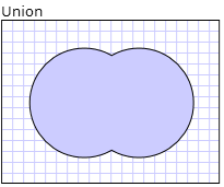
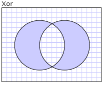
上一節提到 CombinedGeometry 物件和 Combine 方法會結合它們所包含的幾何所定義的區域。 列舉 GeometryCombineMode 會指定如何結合幾何。 屬性的 GeometryCombineMode 可能值為: Union 、、 IntersectExclude 、 和 Xor 。
在下列範例中, CombinedGeometry 會使用聯集的結合模式來定義 。 Geometry1和 Geometry2 都定義為相同半徑的圓形,但中心位移為 50。
<Path Stroke="Black" StrokeThickness="1" Fill="#CCCCFF">
  <Path.Data>

    <!-- Combines two geometries using the union combine mode. -->
    <CombinedGeometry GeometryCombineMode="Union">
      <CombinedGeometry.Geometry1>
        <EllipseGeometry RadiusX="50" RadiusY="50" Center="75,75" />
      </CombinedGeometry.Geometry1>
      <CombinedGeometry.Geometry2>
        <EllipseGeometry RadiusX="50" RadiusY="50" Center="125,75" />
      </CombinedGeometry.Geometry2>
    </CombinedGeometry>
  </Path.Data>
</Path>
在下列範例中, CombinedGeometry 會使用 的合併模式 Xor 來定義 。 Geometry1和 Geometry2 都定義為相同半徑的圓形,但中心位移為 50。
<Path Stroke="Black" StrokeThickness="1" Fill="#CCCCFF">
  <Path.Data>

    <!-- Combines two geometries using the XOR combine mode. -->
    <CombinedGeometry GeometryCombineMode="Xor">
      <CombinedGeometry.Geometry1>
        <EllipseGeometry RadiusX="50" RadiusY="50" Center="75,75" />
      </CombinedGeometry.Geometry1>
      <CombinedGeometry.Geometry2>
        <EllipseGeometry RadiusX="50" RadiusY="50" Center="125,75" />
      </CombinedGeometry.Geometry2>
    </CombinedGeometry>
  </Path.Data>
</Path>
Freezable 功能
因為類別繼承自 Freezable 類別,所以類別 Geometry 提供數個特殊功能: Geometry 物件可以宣告為 XAML 資源 ,在多個物件之間共用、進行唯讀,以改善效能、複製及讓執行緒安全。 如需物件所提供 Freezable 之不同功能的詳細資訊,請參閱 Freezable 物件概觀 。
其他幾何功能
類別 Geometry 也提供實用的公用程式方法,例如:
FillContains - 判斷 Geometry 是否包含另一個 Geometry 。
StrokeContains - 判斷 的 Geometry 筆劃是否包含指定的點。
如需其方法的完整清單,請參閱 類別 Geometry 。
另請參閱
意見反應
即將登場:在 2024 年,我們將逐步淘汰 GitHub 問題作為內容的意見反應機制,並將它取代為新的意見反應系統。 如需詳細資訊,請參閱:https://aka.ms/ContentUserFeedback。
提交並檢視相關的意見反應
