Drawing package requirements
You can convert uploaded drawing packages into map data by using the Azure Maps Conversion service. This article describes the drawing package requirements for the Conversion API. To view a sample package, you can download the sample Drawing package.
Prerequisites
The drawing package includes drawings saved in DWG format, which is the native file format for Autodesk's AutoCAD® software.
You can choose any CAD software to produce the drawings in the drawing package.
The Conversion service converts the drawing package into map data. The Conversion service works with the AutoCAD DWG file format AC1032.
Glossary of terms
For easy reference, here are some terms and definitions that are important as you read this article.
| Term | Definition |
|---|---|
| Layer | An AutoCAD DWG layer from the drawing file. |
| Entity | An AutoCAD DWG entity from the drawing file. |
| Xref | A file in AutoCAD DWG file format, attached to the primary drawing as an external reference. |
| Level | An area of a building at a set elevation. For example, the floor of a building. |
| Feature | An instance of an object produced from the Conversion service that combines a geometry with metadata information. |
| Feature classes | A common blueprint for features. For example, a unit is a feature class, and an office is a feature. |
Drawing package structure
A drawing package is a .zip archive that contains the following files:
- DWG files in AutoCAD DWG file format.
- A manifest.json file that describes the DWG files in the drawing package.
The drawing package must be zipped into a single archive file, with the .zip extension. The DWG files can be organized in any way inside the package, but the manifest file must live at the root directory of the zipped package. The next sections detail the requirements for the DWG files, manifest file, and the content of these files. To view a sample package, you can download the sample drawing package.
DWG file conversion process
The Conversion service does the following on each DWG file:
- Extracts feature classes:
- Levels
- Units
- Zones
- Openings
- Walls
- Vertical penetrations
- Produces a Facility feature.
- Produces a minimal set of default Category features referenced by other features:
- room
- structure
- wall
- opening.door
- zone
- facility
DWG file requirements
A single DWG file is required for each level of the facility. All data of a single level must be contained in a single DWG file. Any external references (xrefs) must be bound to the parent drawing. For example, a facility with three levels has three DWG files in the drawing package.
Each DWG file must adhere to the following requirements:
- The DWG file must define the Exterior and Unit layers. It can optionally define the following layers: Wall, Door, UnitLabel, Zone, and ZoneLabel.
- The DWG file can't contain features from multiple levels.
- The DWG file can't contain features from multiple facilities.
- The DWG must reference the same measurement system and unit of measurement as other DWG files in the drawing package.
DWG layer requirements
Each DWG layer must adhere to the following rules:
- A layer must exclusively contain features of a single class. For example, units and walls can’t be in the same layer.
- A single class of features can be represented by multiple layers.
- Self-intersecting polygons are permitted, but are automatically repaired. When they repaired, the Conversion service raises a warning. It's advisable to manually inspect the repaired results, because they might not match the expected results.
- Each layer has a supported list of entity types. Any other entity types in a layer will be ignored. For example, text entities aren't supported on the wall layer.
The following table outlines the supported entity types and converted map features for each layer. If a layer contains unsupported entity types, then the Conversion service ignores those entities.
| Layer | Entity types | Converted Features |
|---|---|---|
| Exterior | POLYGON, POLYLINE (closed), CIRCLE, or ELLIPSE (closed) | Levels |
| Unit | POLYGON, POLYLINE (closed), CIRCLE, or ELLIPSE (closed) | Units and Vertical penetrations |
| Wall | POLYGON, POLYLINE (closed), CIRCLE, or ELLIPSE (closed), Structures | |
| Door | POLYGON, POLYLINE, LINE, CIRCULARARC, CIRCLE | Openings |
| Zone | POLYGON, POLYLINE (closed), CIRCLE, or ELLIPSE (closed) | Zones |
| UnitLabel | Text (single line) | Not applicable. This layer can only add properties to the unit features from the Units layer. For more information, see the UnitLabel layer. |
| ZoneLabel | Text (single line) | Not applicable. This layer can only add properties to zone features from the ZonesLayer. For more information, see the ZoneLabel layer. |
The following sections describe the requirements for each layer.
Exterior layer
The DWG file for each level must contain a layer to define that level's perimeter. This layer is referred to as the exterior layer. For example, if a facility contains two levels, then it needs to have two DWG files, with an exterior layer for each file.
No matter how many entity drawings are in the exterior layer, the resulting facility dataset contains only one level feature for each DWG file. Additionally:
- Exteriors must be drawn as POLYGON, POLYLINE (closed), CIRCLE, or ELLIPSE (closed).
- Exteriors may overlap, but are dissolved into one geometry.
- Resulting level feature must be at least 4 square meters.
- Resulting level feature must not be greater 400,000 square meters.
If the layer contains multiple overlapping PolyLines, they're dissolved into a single Level feature. Instead, if the layer contains multiple non-overlapping PolyLines, the resulting Level feature has a multi-polygonal representation.
You can see an example of the Exterior layer as the outline layer in the sample drawing package.
Unit layer
The DWG file for each level defines a layer containing units. Units are navigable spaces in the building, such as offices, hallways, stairs, and elevators. If the VerticalPenetrationCategory property is defined, navigable units that span multiple levels, such as elevators and stairs, are converted to Vertical Penetration features. Vertical penetration features that overlap each other are assigned one setid.
The Units layer should adhere to the following requirements:
- Units must be drawn as POLYGON, POLYLINE (closed), CIRCLE, or ELLIPSE (closed).
- Units must fall inside the bounds of the facility exterior perimeter.
- Units must not partially overlap.
- Units must not contain any self-intersecting geometry.
Name a unit by creating a text object in the UnitLabel layer, and then place the object inside the bounds of the unit. For more information, see the UnitLabel layer.
You can see an example of the Units layer in the sample drawing package.
Wall layer
The DWG file for each level can contain a layer that defines the physical extents of walls, columns, and other building structure.
- Walls must be drawn as POLYGON, POLYLINE (closed), CIRCLE, or ELLIPSE (closed).
- The wall layer or layers should only contain geometry that's interpreted as building structure.
You can see an example of the Walls layer in the sample drawing package.
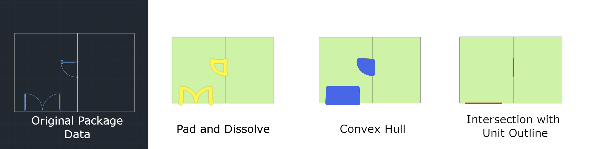
Door layer
You can include a DWG layer that contains doors. Each door must overlap the edge of a unit from the Unit layer.
Door openings in an Azure Maps dataset are represented as a single-line segment that overlaps multiple unit boundaries. The following images show how Azure Maps converts door layer geometry into opening features in a dataset.
Zone layer
The DWG file for each level can contain a Zone layer that defines the physical extents of zones. A zone is a non-navigable space that can be named and rendered. Zones can span multiple levels and are grouped together using the zoneSetId property.
- Zones must be drawn as POLYGON, POLYLINE (closed), or ELLIPSE (closed).
- Zones can overlap.
- Zones can fall inside or outside the facility's exterior perimeter.
Name a zone by creating a text object in the ZoneLabel layer, and placing the text object inside the bounds of the zone. For more information, see ZoneLabel layer.
You can see an example of the Zone layer in the sample drawing package.
UnitLabel layer
The DWG file for each level can contain a UnitLabel layer. The UnitLabel layer adds a name property to units extracted from the Unit layer. Units with a name property can have more details specified in the manifest file.
- Unit labels must be single-line text entities.
- Unit labels must fall entirely inside the bounds of their unit.
- Units must not contain multiple text entities in the UnitLabel layer.
You can see an example of the UnitLabel layer in the sample drawing package.
ZoneLabel layer
The DWG file for each level can contain a ZoneLabel layer. This layer adds a name property to zones extracted from the Zone layer. Zones with a name property can have more details specified in the manifest file.
- Zones labels must be single-line text entities.
- Zones labels must fall inside the bounds of their zone.
- Zones must not contain multiple text entities in the ZoneLabel layer.
You can see an example of the ZoneLabel layer in the sample drawing package.
Manifest file requirements
The zip folder must contain a manifest file at the root level of the directory, and the file must be named manifest.json. It describes the DWG files to allow the Conversion service to parse their content. Only the files identified by the manifest are ingested. Files that are in the zip folder, but aren't properly listed in the manifest, are ignored.
Although there are requirements when you use the manifest objects, not all objects are required. The following table shows the required and optional objects for version 1.1 of the Conversion service.
Note
Unless otherwise specified, all properties with a string property type allow for one thousand characters.
| Object | Required | Description |
|---|---|---|
version |
true | Manifest schema version. Currently, only version 1.1 is supported. |
directoryInfo |
true | Outlines the facility geographic and contact information. It can also be used to outline an occupant geographic and contact information. |
buildingLevels |
true | Specifies the levels of the buildings and the files containing the design of the levels. |
georeference |
true | Contains numerical geographic information for the facility drawing. |
dwgLayers |
true | Lists the names of the layers, and each layer lists the names of its own features. |
unitProperties |
false | Can be used to insert more metadata for the unit features. |
zoneProperties |
false | Can be used to insert more metadata for the zone features. |
The next sections detail the requirements for each object.
directoryInfo
| Property | Type | Required | Description |
|---|---|---|---|
name |
string | true | Name of building. |
streetAddress |
string | false | Address of building. |
unit |
string | false | Unit in building. |
locality |
string | false | Name of a city, town, area, neighborhood, or region. |
adminDivisions |
JSON array of strings | false | An array containing address designations. For example: (Country, State) Use ISO 3166 country codes and ISO 3166-2 state/territory codes. |
postalCode |
string | false | The mail sorting code. |
hoursOfOperation |
string | false | Adheres to the OSM Opening Hours format. |
phone |
string | false | Phone number associated with the building. |
website |
string | false | Website associated with the building. |
nonPublic |
bool | false | Flag specifying if the building is open to the public. |
anchorLatitude |
numeric | false | Latitude of a facility anchor (pushpin). |
anchorLongitude |
numeric | false | Longitude of a facility anchor (pushpin). |
anchorHeightAboveSeaLevel |
numeric | false | Height of the facility's ground floor above sea level, in meters. |
defaultLevelVerticalExtent numeric |
false | Default height (thickness) of a level of this facility to use when a level's verticalExtent is undefined. |
buildingLevels
The buildingLevels object contains a JSON array of buildings levels.
| Property | Type | Required | Description |
|---|---|---|---|
levelName |
string | true | Descriptive level name. For example: Floor 1, Lobby, Blue Parking, or Basement. |
ordinal |
integer | true | Determines the vertical order of levels. Every facility must have a level with ordinal 0. |
heightAboveFacilityAnchor |
numeric | false | Level height above the anchor in meters. |
verticalExtent |
numeric | false | Floor-to-ceiling height (thickness) of the level in meters. |
filename |
string | true | File system path of the CAD drawing for a building level. It must be relative to the root of the building's zip file. |
georeference
| Property | Type | Required | Description |
|---|---|---|---|
lat |
numeric | true | Decimal representation of degrees latitude at the facility drawing's origin. The origin coordinates must be in WGS84 Web Mercator (EPSG:3857). |
lon |
numeric | true | Decimal representation of degrees longitude at the facility drawing's origin. The origin coordinates must be in WGS84 Web Mercator (EPSG:3857). |
angle |
numeric | true | The clockwise angle, in degrees, between true north and the drawing's vertical (Y) axis. |
dwgLayers
| Property | Type | Required | Description |
|---|---|---|---|
exterior |
array of strings | true | Names of layers that define the exterior building profile. |
unit |
array of strings | false | Names of layers that define units. |
wall |
array of strings | false | Names of layers that define walls. |
door |
array of strings | false | Names of layers that define doors. |
unitLabel |
array of strings | false | Names of layers that define names of units. |
zone |
array of strings | false | Names of layers that define zones. |
zoneLabel |
array of strings | false | Names of layers that define names of zones. |
unitProperties
The unitProperties object contains a JSON array of unit properties.
| Property | Type | Required | Description |
|---|---|---|---|
unitName |
string | true | Name of unit to associate with this unitProperty record. This record is only valid when a label matching unitName is found in the unitLabel layers. |
categoryName |
string | false | Purpose of the unit. A list of values that the provided rendering styles can make use of is documented in categories.json. |
occupants |
array of directoryInfo objects | false | List of occupants for the unit. |
nameAlt |
string | false | Alternate name of the unit. |
nameSubtitle |
string | false | Subtitle of the unit. |
addressRoomNumber |
string | false | Room, unit, apartment, or suite number of the unit. |
verticalPenetrationCategory |
string | false | When this property is defined, the resulting feature is a vertical penetration (VRT) rather than a unit. You can use vertical penetrations to go to other vertical penetration features in the levels above or below it. Vertical penetration is a Category name. If this property is defined, the categoryName property is overridden with verticalPenetrationCategory. |
verticalPenetrationDirection |
string | false | If verticalPenetrationCategory is defined, optionally define the valid direction of travel. The permitted values are: lowToHigh, highToLow, both, and closed. The default value is both. The value is case-sensitive. |
nonPublic |
bool | false | Indicates if the unit is open to the public. |
isRoutable |
bool | false | When this property is set to false, you can't go to or through the unit. The default value is true. |
isOpenArea |
bool | false | Allows the navigating agent to enter the unit without the need for an opening attached to the unit. By default, this value is set to true for units with no openings, and false for units with openings. Manually setting isOpenArea to false on a unit with no openings results in a warning, because the resulting unit isn't reachable by a navigating agent. |
zoneProperties
The zoneProperties object contains a JSON array of zone properties.
| Property | Type | Required | Description |
|---|---|---|---|
| zoneName | string | true | Name of zone to associate with zoneProperty record. This record is only valid when a label matching zoneName is found in the zoneLabel layer of the zone. |
| categoryName | string | false | Purpose of the zone. A list of values that the provided rendering styles can make use of is documented in categories.json. |
| zoneNameAlt | string | false | Alternate name of the zone. |
| zoneNameSubtitle | string | false | Subtitle of the zone. |
| zoneSetId | string | false | Set ID to establish a relationship among multiple zones so that they can be queried or selected as a group. For example, zones that span multiple levels. |
Sample drawing package manifest
The following is the manifest file for the sample drawing package. Go to the Sample drawing package for Azure Maps Creator on GitHub to download the entire package.
Manifest file
{
    "version": "1.1",
    "directoryInfo": {
        "name": "Contoso Building",
        "streetAddress": "Contoso Way",
        "unit": "1",
        "locality": "Contoso eastside",
        "postalCode": "98052",
        "adminDivisions": [
            "Contoso city",
            "Contoso state",
            "Contoso country"
        ],
        "hoursOfOperation": "Mo-Fr 08:00-17:00 open",
        "phone": "1 (425) 555-1234",
        "website": "www.contoso.com",
        "nonPublic": false,
        "anchorLatitude": 47.636152,
        "anchorLongitude": -122.132600,
        "anchorHeightAboveSeaLevel": 1000,
        "defaultLevelVerticalExtent": 3
    },
    "buildingLevels": {
        "levels": [
            {
                "levelName": "Basement",
                "ordinal": -1,
                "filename": "./Basement.dwg"
            }, {
                "levelName": "Ground",
                "ordinal": 0,
                "verticalExtent": 5,
                "filename": "./Ground.dwg"
            }, {
                "levelName": "Level 2",
                "ordinal": 1,
                "heightAboveFacilityAnchor": 3.5,
                "filename": "./Level_2.dwg"
            }
        ]
    },
    "georeference": {
        "lat": 47.636152,
        "lon": -122.132600,
        "angle": 0
    },
    "dwgLayers": {
        "exterior": [
            "OUTLINE", "WINDOWS"
        ],
        "unit": [
            "UNITS"
        ],
        "wall": [
            "WALLS"
        ],
        "door": [
            "DOORS"
        ],
        "unitLabel": [
            "UNITLABELS"
        ],
        "zone": [
            "ZONES"
        ],
        "zoneLabel": [
            "ZONELABELS"
        ]
    },
    "unitProperties": [
        {
            "unitName": "B01",
            "categoryName": "room.office",
            "occupants": [
                {
                    "name": "Joe's Office",
                    "phone": "1 (425) 555-1234"
                }
            ],
            "nameAlt": "Basement01",
            "nameSubtitle": "01",
            "addressRoomNumber": "B01",
            "nonPublic": true,
            "isRoutable": true,
            "isOpenArea": true
        },
        {
            "unitName": "B02"
        },
        {
            "unitName": "B05",
            "categoryName": "room.office"
        },
        {
            "unitName": "STRB01",
            "verticalPenetrationCategory": "verticalPenetration.stairs",
            "verticalPenetrationDirection": "both"
        },
        {
            "unitName": "ELVB01",
            "verticalPenetrationCategory": "verticalPenetration.elevator",
            "verticalPenetrationDirection": "high_to_low"
        }
    ],
    "zoneProperties":
    [
        {
            "zoneName": "WifiB01",
            "categoryName": "Zone",
            "zoneNameAlt": "MyZone",
            "zoneNameSubtitle": "Wifi",
            "zoneSetId": "1234"
        },
        {
            "zoneName": "Wifi101",
            "categoryName": "Zone",
            "zoneNameAlt": "MyZone",
            "zoneNameSubtitle": "Wifi",
            "zoneSetId": "1234"
        }
    ]
}
You can convert uploaded drawing packages into map data by using the Azure Maps Conversion service. This article describes the drawing package requirements for the Conversion API. To view a sample package, you can download the sample drawing package v2.
For a guide on how to prepare your drawing package, see Drawing Package Guide.
Changes and Revisions
- Added support for user defined feature classes.
- Simplified requirements of DWG layers.
Prerequisites
The drawing package includes drawings saved in DWG format, which is the native file format for Autodesk's AutoCAD® software.
You can choose any CAD software to produce the drawings in the drawing package.
The Conversion service converts the drawing package into map data. The Conversion service works with the AutoCAD DWG file format AC1032.
Glossary of terms
For easy reference, here are some terms and definitions that are important as you read this article.
| Term | Definition |
|---|---|
| Layer | An AutoCAD DWG layer from the drawing file. |
| Entity | An AutoCAD DWG entity from the drawing file. |
| Xref | A file in AutoCAD DWG file format, attached to the primary drawing as an external reference. |
| Level | An area of a facility at a set elevation. For example, the floor of a facility. |
| Feature | An instance of an object produced from the Conversion service that combines a geometry with metadata information. |
| Feature classes | A common blueprint for features. |
Drawing package structure
A drawing package is a ZIP archive that contains the following files:
- DWG files in AutoCAD DWG file format.
- A manifest.json file that describes the DWG files in the drawing package.
The drawing package must be compressed into a single archive file, with the .zip extension. The DWG files can be organized in any way inside the drawing package, but the manifest file must be in the root directory. The next sections explain the conversion process and requirements for both the DWG and manifest files, and the content of these files. To view a sample package, you can download the sample drawing package v2.
DWG file conversion process
The Azure Maps Conversion service converts DWG file(s) of a facility to map data representing a facility and features of a facility.
The Azure Maps Conversion service creates:
- Facility Feature: The top-level feature of a facility that all levels of a facility are associated to.
- Level features: One Level feature is created for each floor of a facility. All features on a level are associated with a level.
- User defined features: DWG layers are mapped to a user defined feature class and become instances of the feature class.
DWG file requirements
Each DWG file must adhere to these requirements:
- The DWG file can't contain features from multiple facilities.
- The DWG file can't contain features from multiple levels. For example, a facility with three levels has three DWG files in the drawing package.
- All data of a single level must be contained in a single DWG file. Any external references (xrefs) must be bound to the parent drawing.
- The DWG file must define layer(s) representing the boundary of that level.
- The DWG must reference the same measurement system and unit of measurement as other DWG files in the drawing package.
- The DWG file must be aligned when stacked on top of another level from the same facility.
DWG layer requirements
Feature classes
One or more DWG layer(s) can be mapped to a user defined feature class. One instance of the feature is created from an entity on the mapped layer. For example, DWG layers chair, table, and couch are mapped to a feature class called furniture. A furniture feature is created for every entity from the defined layers. Additionally:
- All layers should be separated to represent different feature types of the facility.
- All entities must fall inside the bounds of the level perimeter.
- Supported AutoCAD entity types: TEXT, MTEXT, POINT, ARC, CIRCLE, LINE, POLYLINE, ELLIPSE.
Feature class properties
Text entities that fall within the bounds of a closed shape can be associated to that feature as a property. For example, a room feature class might have text that describes the room name and another the room type sample drawing package v2. Additionally:
- Only TEXT and MTEXT entities are associated to the feature as a property. All other entity types are ignored.
- The TEXT and MTEXT justification point must fall within the bounds of the closed shape.
- If more than one TEXT property is within the bounds of the closed shape and both are mapped to one property, one is randomly selected.
Facility level
The DWG file for each level must contain a layer to define that level's perimeter. For example, if a facility contains two levels, then it needs to have two DWG files, each with a layer that defines that level's perimeter.
No matter how many entity drawings are in the level perimeter layer, the resulting facility dataset contains only one level feature for each DWG file. Additionally:
- Level perimeters must be drawn as POLYGON, POLYLINE (closed), CIRCLE, or ELLIPSE (closed).
- Level perimeters may overlap but are dissolved into one geometry.
- The resulting level feature must be at least 4 square meters.
- The resulting level feature must not be greater than 400,000 square meters.
If the layer contains multiple overlapping POLYLINES, they're combined into a single Level feature. Instead, if the layer contains multiple nonoverlapping POLYLINES, the resulting Level feature has a multi-polygonal representation.
You can see an example of the Level perimeter layer as the GROS$ layer in the sample drawing package v2.
Manifest file requirements
The drawing package must contain a manifest file at the root level and the file must be named manifest.json. It describes the DWG files allowing the Conversion service to parse their content. Only the files identified by the manifest are used. Files that are in the drawing package, but aren't properly listed in the manifest, are ignored.
The file paths in the buildingLevels object of the manifest file must be relative to the root of the drawing package. The DWG file name must exactly match the name of the facility level. For example, a DWG file for the "Basement" level is Basement.dwg. A DWG file for level 2 is named as level_2.dwg. Filenames can't contain spaces, you can use an underscore to replace any spaces.
Although there are requirements when you use the manifest objects, not all objects are required. The following table shows the required and optional objects for the 2023-03-01-preview Conversion service.
Note
Unless otherwise specified, all string properties are limited to one thousand characters.
Manifest JSON file
| Property | Type | Required | Description |
|---|---|---|---|
version |
string | TRUE | Manifest schema version. Currently version "2.0" |
buildingLevels |
BuildingLevels object | TRUE | Specifies the levels of the facility and the files containing the design of the levels. |
featureClasses |
Array of featureClass objects | TRUE | List of feature class objects that define how layers are read from the DWG drawing file. |
georeference |
Georeference object | FALSE | Contains numerical geographic information for the facility drawing. |
facilityName |
string | FALSE | The name of the facility. |
The next sections detail the requirements for each object.
buildingLevels
| Property | Type | Required | Description |
|---|---|---|---|
dwgLayers |
Array of strings | TRUE | Names of layers that define the exterior profile of the facility. |
levels |
Array of level objects | TRUE | A level refers to a unique floor in the facility defined in a DWG file, the height of each level and vertical order in which they appear. |
level
| Property | Type | Required | Description |
|---|---|---|---|
levelName |
string | TRUE | The name of the level. For example: Floor 1, Lobby, Blue Parking, or Basement. |
ordinal |
integer | TRUE | Defines the vertical order of levels. All ordinal values must be unique within a facility. |
filename |
string | TRUE | The path and name of the DWG file representing the level in a facility. The path must be relative to the root of the drawing package. |
verticalExtent |
number | FALSE | Floor-to-ceiling vertical height (thickness) of the level in meters. |
featureClass
| Property | Type | Required | Description |
|---|---|---|---|
dwgLayers |
Array of strings | TRUE | The name of each layer that defines the feature class. Each entity on the specified layer is converted to an instance of the feature class. The dwgLayer name that a feature is converted from ends up as a property of that feature. |
featureClassName |
String | TRUE | The name of the feature class. Typical examples include room, workspace or wall. |
featureClassProperties |
Array of featureClassProperty objects | FALSE | Specifies text layers in the DWG file associated to the feature as a property. For example, a label that falls inside the bounds of a space, such as a room number. |
featureClassProperty
| Property | Type | Required | Description |
|---|---|---|---|
dwgLayers |
Array of strings | TRUE | The name of each layer that defines the feature class property. Each entity on the specified layer is converted to a property. Only the DWG TEXT and MTEXT entities are converted to properties. All other entities are ignored. |
featureClassPropertyName |
String | TRUE | Name of the feature class property, for example, spaceName or spaceUseType. |
georeference
| Property | Type | Required | Description |
|---|---|---|---|
lat |
number | TRUE | Decimal representation of degrees latitude at the facility drawing's origin. The origin coordinates must be in WGS84 Web Mercator (EPSG:3857). |
lon |
number | TRUE | Decimal representation of degrees longitude at the facility drawing's origin. The origin coordinates must be in WGS84 Web Mercator (EPSG:3857). |
angle |
number | TRUE | The clockwise angle, in degrees, between true north and the drawing's vertical (Y) axis. |
Sample drawing package manifest
The JSON in this example shows the manifest file for the sample drawing package. Go to the sample drawing package v2 for Azure Maps Creator on GitHub to download the entire package.
Manifest file
{
  "version": "2.0",
  "buildingLevels": {
    "dwgLayers": [
      "GROS$"
    ],
    "levels": [
      {
        "filename": "Ground.dwg",
        "levelName": "level 1",
        "ordinal": 0
      },
      {
        "filename": "Level_2.dwg",
        "levelName": "level 2",
        "ordinal": 1
      }
    ]
  },
  "georeference": {
    "lat": 47.63529901,
    "lon": -122.13355885,
    "angle": 0
  },
  "featureClasses": [
    {
      "featureClassName": "room",
      "dwgLayers": [
        "RM$"
      ],
      "featureClassProperties": [
        {
          "featureClassPropertyName": "name",
          "dwgLayers": [
            "A-IDEN-NUMR-EXST"
          ]
        },
        {
          "featureClassPropertyName": "roomType",
          "dwgLayers": [
            "A-IDEN-NAME-EXST"
          ]
        }
      ]
    },
    {
      "featureClassName": "wall",
      "dwgLayers": [
        "A-WALL-EXST",
        "A-WALL-CORE-EXST",
        "A-GLAZ-SILL-EXST",
        "A-GLAZ-SHEL-SILL-EXST",
        "A-GLAZ-SHEL-EXST",
        "A-GLAZ-EXST"
      ]
    },
    {
      "featureClassName": "workspace",
      "dwgLayers": [
        "A-BOMA"
      ]
    },
    {
      "featureClassName": "workspaceFurniture",
      "dwgLayers": [
        "A-FURN-SYTM-EXST"
      ]
    },
    {
      "featureClassName": "buildingFurniture",
      "dwgLayers": [
        "A-FURN-FREE-EXST"
      ]
    }
  ],
  "facilityName": "Contoso Building"
}
Next steps
For a guide on how to prepare your drawing package, see the drawing package guide.
Feedback
Coming soon: Throughout 2024 we will be phasing out GitHub Issues as the feedback mechanism for content and replacing it with a new feedback system. For more information see: https://aka.ms/ContentUserFeedback.
Submit and view feedback for