Note
Access to this page requires authorization. You can try signing in or changing directories.
Access to this page requires authorization. You can try changing directories.
This tutorial shows you a simple and effective way to implement high availability and disaster recovery (HA/DR) for Java using Oracle WebLogic Server (WLS) on Azure Virtual Machines (VMs). The solution illustrates how to achieve a low Recovery Time Objective (RTO) and Recovery Point Objective (RPO) using a simple database driven Jakarta EE application running on WLS. HA/DR is a complex topic, with many possible solutions. The best solution depends on your unique requirements. For other ways to implement HA/DR, see the resources at the end of this article.
In this tutorial, you learn how to:
- Use Azure optimized best practices to achieve high availability and disaster recovery.
- Set up a Microsoft Azure SQL Database failover group in paired regions.
- Set up paired WLS clusters on Azure VMs.
- Set up an Azure Traffic Manager.
- Configure WLS clusters for high availability and disaster recovery.
- Test failover from primary to secondary.
The following diagram illustrates the architecture you build:

Azure Traffic Manager checks the health of your regions and routes the traffic accordingly to the application tier. Both the primary region and the secondary region have a full deployment of the WLS cluster. However, only the primary region is actively servicing network requests from the users. The secondary region is passive and activated to receive traffic only when the primary region experiences a service disruption. Azure Traffic Manager uses the health check feature of the Azure Application Gateway to implement this conditional routing. The primary WLS cluster is running and the secondary cluster is shut down. The geo-failover RTO of the application tier depends on the time for starting VMs and running the secondary WLS cluster. The RPO depends on the Azure SQL Database because the data is persisted and replicated in the Azure SQL Database failover group.
The database tier consists of an Azure SQL Database failover group with a primary server and a secondary server. The primary server is in active read-write mode and connected to the primary WLS cluster. The secondary server is in passive ready-only mode and connected to the secondary WLS cluster. A geo-failover switches all secondary databases in the group to the primary role. For geo-failover RPO and RTO of Azure SQL Database, see Overview of Business Continuity.
This article was written with the Azure SQL Database service because the article relies on the high availability (HA) features of that service. Other database choices are possible, but you must consider the HA features of whatever database you choose. For more information, including information on how to optimize the configuration of data sources for replication, see Configuring Data Sources for Oracle Fusion Middleware Active-Passive Deployment.
Prerequisites
- An Azure subscription. If you don't have an Azure subscription, create a free account before you begin.
- Make sure you have either the
Ownerrole or theContributorandUser Access Administratorroles in the subscription. You can verify the assignment by following the steps in List Azure role assignments using the Azure portal. - Prepare a local machine with Windows, Linux, or macOS installed.
- Install and set up Git.
- Install a Java SE implementation, version 17 or later - for example, the Microsoft build of OpenJDK.
- Install Maven, version 3.9.3 or later.
Set up an Azure SQL Database failover group in paired regions
In this section, you create an Azure SQL Database failover group in paired regions for use with your WLS clusters and app. In a later section, you configure WLS to store its session data and transaction log (TLOG) data to this database. This practice is consistent with Oracle's Maximum Availability Architecture (MAA). This guidance provides an Azure adaptation for MAA. For more information on MAA, see Oracle Maximum Availability Architecture.
First, create the primary Azure SQL Database by following the Azure portal steps in Quickstart: Create a single database - Azure SQL Database. Follow the steps up to, but not including, the "Clean up resources" section. Use the following directions as you go through the article, then return to this article after you create and configure the Azure SQL Database:
When you reach the section Create a single database, use the following steps:
- In step 4 for creating new resource group, save aside the Resource group name value - for example, myResourceGroup.
- In step 5 for database name, save aside the Database name value - for example, mySampleDatabase.
- In step 6 for creating the server, use the following steps:
- Save aside the unique server name - for example, sqlserverprimary-ejb120623.
- For Location, select (US) East US.
- For Authentication method, select Use SQL authentication.
- Save aside the Server admin login value - for example, azureuser.
- Save aside the Password value.
- In step 8, for Workload environment, select Development. Look at the description and consider other options for your workload.
- In step 11, for Backup storage redundancy, select Locally-redundant backup storage. Consider other options for your backups. For more information, see the Backup storage redundancy section of Automated backups in Azure SQL Database.
- In step 14, in the Firewall rules configuration, for Allow Azure services and resources to access this server, select Yes.
When you reach the section Query the database, use the following steps:
In step 3, enter your SQL authentication server admin sign-in information to sign in.
Note
If sign-in fails with an error message similar to Client with IP address 'xx.xx.xx.xx' is not allowed to access the server, select Allowlist IP xx.xx.xx.xx on server <your-sqlserver-name> at the end of the error message. Wait until the server firewall rules complete updating, then select OK again.
After you run the sample query in step 5, clear the editor and create tables.
Enter the following query to create schema for TLOG.
create table TLOG_msp1_WLStore (ID DECIMAL(38) NOT NULL, TYPE DECIMAL(38) NOT NULL, HANDLE DECIMAL(38) NOT NULL, RECORD VARBINARY(MAX) NOT NULL, PRIMARY KEY (ID));
create table TLOG_msp2_WLStore (ID DECIMAL(38) NOT NULL, TYPE DECIMAL(38) NOT NULL, HANDLE DECIMAL(38) NOT NULL, RECORD VARBINARY(MAX) NOT NULL, PRIMARY KEY (ID));
create table TLOG_msp3_WLStore (ID DECIMAL(38) NOT NULL, TYPE DECIMAL(38) NOT NULL, HANDLE DECIMAL(38) NOT NULL, RECORD VARBINARY(MAX) NOT NULL, PRIMARY KEY (ID));
create table wl_servlet_sessions (wl_id VARCHAR(100) NOT NULL, wl_context_path VARCHAR(100) NOT NULL, wl_is_new CHAR(1), wl_create_time DECIMAL(20), wl_is_valid CHAR(1), wl_session_values VARBINARY(MAX), wl_access_time DECIMAL(20), wl_max_inactive_interval INTEGER, PRIMARY KEY (wl_id, wl_context_path));
After a successful run, you should see the message Query succeeded: Affected rows: 0.
These database tables are used for storing transaction log (TLOG) and session data for your WLS clusters and app. For more information, see Using a JDBC TLOG Store and Using a Database for Persistent Storage (JDBC Persistence).
Next, create an Azure SQL Database failover group by following the Azure portal steps in Configure a failover group for Azure SQL Database. You just need the following sections: Create failover group and Test planned failover. Use the following steps as you go through the article, then return to this article after you create and configure the Azure SQL Database failover group:
When you reach the section Create failover group, use the following steps:
- In step 5 for creating the failover group, select the option to create a new secondary server and then use the following steps:
- Enter and save aside the failover group name - for example, failovergroupname-ejb120623.
- Enter and save aside the unique server name - for example, sqlserversecondary-ejb120623.
- Enter the same server admin and password as your primary server.
- For Location, select a different region than the one you used for the primary database.
- Make sure Allow Azure services to access server is selected.
- In step 5 for configuring the Databases within the group, select the database you created in the primary server - for example, mySampleDatabase.
- In step 5 for creating the failover group, select the option to create a new secondary server and then use the following steps:
After you complete all the steps in the section Test planned failover, keep the failover group page open and use it for the failover test of the WLS clusters later.
Note
This article guides you to create an Azure SQL Database single database with SQL authentication for simplicity because the HA/DR setup this article focuses on is already very complex. A more secure practice is to use Microsoft Entra authentication for Azure SQL for authenticating the database server connection. For information on how to configure the database connection with Microsoft Entra authentication, see Configure passwordless database connections for Java apps on Oracle WebLogic Server.
Set up paired WLS clusters on Azure VMs
In this section, you create two WLS clusters on Azure VMs using the Oracle WebLogic Server Cluster on Azure VMs offer. The cluster in East US is primary and is configured as the active cluster later. The cluster in West US is secondary and is configured as the passive cluster later.
Set up the primary WLS cluster
First, open the Oracle WebLogic Server Cluster on Azure VMs offer in your browser and select Create. You should see the Basics pane of the offer.
Use the following steps to fill out the Basics pane:
- Ensure that the value shown for Subscription is the same one that has the roles listed in the prerequisites section.
- In the Resource group field, select Create new and fill in a unique value for the resource group - for example, wls-cluster-eastus-ejb120623.
- Under Instance details, for Region, select East US.
- Under Credentials for Virtual Machines and WebLogic, provide a password for admin account of VM and WebLogic Administrator, respectively. Save aside the username and password for WebLogic Administrator. For better security, consider using SSH Public Key as the VM authentication type.
- Leave the defaults for other fields.
- Select Next to go to the TLS/SSL Configuration pane.

Leave the defaults in the TLS/SSL Configuration pane, select Next to go to Azure Application Gateway pane, and then use the following steps.
- For Connect to Azure Application Gateway?, select Yes.
- For Select desired TLS/SSL certificate option, select Generate a self-signed certificate.
- Select Next to go to the Networking pane.

You should see all fields pre-populated with the defaults in the Networking pane. Use the following steps to save the network configuration:
Select Edit virtual network. Save aside the address space of the virtual network - for example, 10.1.4.0/23.
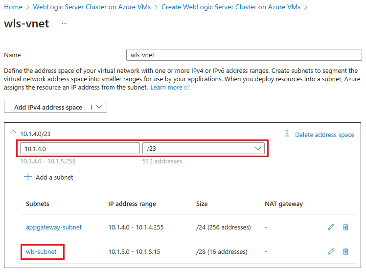
Select
wls-subnetto edit the subnet. Under Subnet details, save aside the starting address and subnet size - for example, 10.1.5.0 and /28.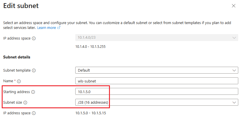
If you make any modifications, save the changes.
Return to Networking pane.
Select Next to go to the Database pane.


The following steps show you how to fill out the Database pane:
- For Connect to database?, select Yes.
- For Choose database type, select Microsoft SQL Server (Support passwordless connection) .
- For JNDI Name, enter jdbc/WebLogicCafeDB.
- For DataSource Connection String, replace the placeholders with the values you saved aside in the preceding section for the primary SQL Database - for example, jdbc:sqlserver://sqlserverprimary-ejb120623.database.windows.net:1433;database=mySampleDatabase.
- For Global transaction protocol, select None.
- For Database username, replace the placeholders with the values you saved aside in the preceding section for the primary SQL Database - for example, azureuser@sqlserverprimary-ejb120623.
- Enter the server admin sign-in password that you saved aside previously for Database Password. Enter the same value for Confirm password.
- Leave the defaults for the other fields.
- Select Review + create.
- Wait until Running final validation... successfully completes, then select Create.

Note
This article guides you to connect to an Azure SQL Database with SQL authentication for simplicity because the HA/DR setup this article focuses on is already very complex. A more secure practice is to use Microsoft Entra authentication for Azure SQL for authenticating the database server connection. For information on how to configure the database connection with Microsoft Entra authentication, see Configure passwordless database connections for Java apps on Oracle WebLogic Server.
After a while, you should see the Deployment page where Deployment is in progress is displayed.
Note
If you see any problems during Running final validation..., fix them and try again.
Depending on network conditions and other activity in your selected region, the deployment can take up to 50 minutes to complete. After that, you should see the text Your deployment is complete displayed on the deployment page.
In the meantime, you can set up the secondary WLS cluster in parallel.
Set up the secondary WLS cluster
Follow the same steps in as in the section Set up the primary WLS cluster to set up the secondary WLS cluster in West US region, except for the following differences:
In the Basics pane, use the following steps:
- In the Resource group field, select Create new and fill in a different unique value for the resource group - for example, wls-cluster-westtus-ejb120623.
- Under Instance details, for Region, select West US.
In the Networking pane, use the following steps:
For Edit virtual network, enter same address space of the virtual network as your primary WLS cluster - for example, 10.1.4.0/23.
Note
You should see a warning message similar to the following one: Address space '10.1.4.0/23 (10.1.4.0 - 10.1.5.255)' overlaps with address space '10.1.4.0/23 (10.1.4.0 - 10.1.5.255)' of virtual network 'wls-vnet'. Virtual networks with overlapping address space cannot be peered. If you intend to peer these virtual networks, change address space '10.1.4.0/23 (10.1.4.0 - 10.1.5.255)'. You can ignore this message because you need two WLS clusters with the same network configuration.
For
wls-subnet, enter same starting address and subnet size as your primary WLS cluster - for example, 10.1.5.0 and /28.
In the Database pane, use the following steps:
- For DataSource Connection String, replace the placeholders with the values you saved aside in the preceding section for the secondary SQL Database - for example, jdbc:sqlserver://sqlserversecondary-ejb120623.database.windows.net:1433;database=mySampleDatabase.
- For Database username, replace the placeholders with the values you saved aside in the preceding section for the secondary SQL Database - for example, azureuser@sqlserversecondary-ejb120623.
Mirror the network settings for the two clusters
During the phase of resuming pending transactions in the secondary WLS cluster after a failover, WLS checks the ownership of the TLOG store. To successfully pass the check, all managed servers in the secondary cluster must have same private IP address as the primary cluster.
This section shows you how to mirror the network settings from the primary cluster to the secondary cluster.
First, use the following steps to configure network settings for the primary cluster after its deployment completes:
In Overview pane of the Deployment page, select Go to resource group.
Select the network interface
adminVM_NIC_with_pub_ip.- Under Settings, select IP configurations.
- Select
ipconfig1. - Under Private IP address settings, select Static for Allocation. Save aside the private IP address.
- Select Save.
Return to the resource group of the primary WLS cluster, then repeat step 3 for the network interfaces
mspVM1_NIC_with_pub_ip,mspVM2_NIC_with_pub_ip, andmspVM3_NIC_with_pub_ip.Wait until all updates complete. You can select the notifications icon in the Azure portal to open the Notifications pane for status monitoring.

Return to the resource group of the primary WLS cluster, then copy the name for the resource with type Private endpoint - for example, 7e8c8bsaep. Use that name to find the remaining network interface - for example, 7e8c8bsaep.nic.c0438c1a-1936-4b62-864c-6792eec3741a. Select it and follow the preceding steps to get its private IP address.
Then, use the following steps to configure the network settings for the secondary cluster after its deployment completes:
In the Overview pane of the Deployment page, select Go to resource group.
For the network interfaces
adminVM_NIC_with_pub_ip,mspVM1_NIC_with_pub_ip,mspVM2_NIC_with_pub_ip, andmspVM3_NIC_with_pub_ip, follow the preceding steps to update the private IP address allocation to Static.Wait until all updates complete.
For the network interfaces
mspVM1_NIC_with_pub_ip,mspVM2_NIC_with_pub_ip, andmspVM3_NIC_with_pub_ip, follow the preceding steps but update the private IP address to the same value used with the primary cluster. Wait until the current update of network interface completes before proceeding to next one.Note
You can't change the private IP address of the network interface that is part of a private endpoint. To easily mirror the private IP addresses of network interfaces for managed servers, consider updating the private IP address for
adminVM_NIC_with_pub_ipto an IP address that isn't used. Depending on the allocation of private IP addresses in your two clusters, you might need to update the private IP address in the primary cluster as well.
The following table shows an example of mirroring the network settings for two clusters:
| Cluster | Network interface | Private IP address (before) | Private IP address (after) | Update sequence |
|---|---|---|---|---|
| Primary | 7e8c8bsaep.nic.c0438c1a-1936-4b62-864c-6792eec3741a |
10.1.5.4 |
10.1.5.4 |
|
| Primary | adminVM_NIC_with_pub_ip |
10.1.5.7 |
10.1.5.7 |
|
| Primary | mspVM1_NIC_with_pub_ip |
10.1.5.5 |
10.1.5.5 |
|
| Primary | mspVM2_NIC_with_pub_ip |
10.1.5.8 |
10.1.5.9 |
1 |
| Primary | mspVM3_NIC_with_pub_ip |
10.1.5.6 |
10.1.5.6 |
|
| Secondary | 1696b0saep.nic.2e19bf46-9799-4acc-b64b-a2cd2f7a4ee1 |
10.1.5.8 |
10.1.5.8 |
|
| Secondary | adminVM_NIC_with_pub_ip |
10.1.5.5 |
10.1.5.4 |
4 |
| Secondary | mspVM1_NIC_with_pub_ip |
10.1.5.7 |
10.1.5.5 |
5 |
| Secondary | mspVM2_NIC_with_pub_ip |
10.1.5.6 |
10.1.5.9 |
2 |
| Secondary | mspVM3_NIC_with_pub_ip |
10.1.5.4 |
10.1.5.6 |
3 |
Check the set of private IP addresses for all managed servers, which consists of the backend pool of the Azure Application Gateway you deployed in each cluster. If it's updated, use the following steps to update the Azure Application Gateway backend pool accordingly:
- Open the resource group of the cluster.
- Find the resource myAppGateway with the type Application gateway. Select it to open it.
- In the Settings section, select Backend pools, then select
myGatewayBackendPool. - Change the Backend targets values with the updated private IP address or addresses, then select Save. Wait until it completes.
- In the Settings section, select Health probes, then select HTTPhealthProbe.
- Make sure I want to test the backend health before adding the health probe is selected, then select Test. You should see that the Status value of the backend pool
myGatewayBackendPoolis marked as healthy. If it isn't, check whether private IP addresses are updated as expected and the VMs are running, then test the health probe again. You must troubleshoot and resolve the issue before you continue.
In the following example, the Azure Application Gateway backend pool for each cluster is updated:
| Cluster | Azure Application Gateway backend pool | Backend targets (before) | Backend targets (after) |
|---|---|---|---|
| Primary | myGatewayBackendPool |
(10.1.5.5, 10.1.5.8, 10.1.5.6) |
(10.1.5.5, 10.1.5.9, 10.1.5.6) |
| Secondary | myGatewayBackendPool |
(10.1.5.7, 10.1.5.6, 10.1.5.4) |
(10.1.5.5, 10.1.5.9, 10.1.5.6) |
To automate the network settings mirroring, consider using Azure CLI. For more information, see Get started with Azure CLI.
Verify the deployments of the clusters
You deployed an Azure Application Gateway and a WLS admin server in each cluster. The Azure Application Gateway acts as load balancer for all managed servers in the cluster. The WLS admin server provides a web console for cluster configuration.
Use the following steps to verify whether the Azure Application Gateway and WLS admin console in each cluster work before moving to next step:
- Return to the Deployment page, then select Outputs.
- Copy the value of the property appGatewayURL. Append the string weblogic/ready and then open that URL in a new browser tab. You should see an empty page without any error message. If you don't, you must troubleshoot and resolve the issue before you continue.
- Copy and save aside the value of the property adminConsole. Open it in a new browser tab. You should see the sign-in page of the WebLogic Server Administration Console. Sign in to the console with the user name and password for WebLogic administrator you saved aside previously. If you aren't able to sign in, you must troubleshoot and resolve the issue before you continue.
Use the following steps to get the IP address of the Azure Application Gateway for each cluster. You use these values when you set up the Azure Traffic Manager later.
- Open the resource group where your cluster is deployed - for example, select Overview to switch back to the Overview pane of the deployment page. Then, select Go to resource group.
- Find the resource
gwipwith the type Public IP address, then select it to open it. Look for the IP address field and save aside its value.
Set up an Azure Traffic Manager
In this section, you create an Azure Traffic Manager for distributing traffic to your public facing applications across the global Azure regions. The primary endpoint points to the Azure Application Gateway in the primary WLS cluster, and the secondary endpoint points to the Azure Application Gateway in the secondary WLS cluster.
Create an Azure Traffic Manager profile by following Quickstart: Create a Traffic Manager profile using the Azure portal. Skip the Prerequisites section. You just need the following sections: Create a Traffic Manager profile, Add Traffic Manager endpoints, and Test Traffic Manager profile. Use the following steps as you go through these sections, then return to this article after you create and configure the Azure Traffic Manager.
When you reach the section Create a Traffic Manager profile, in step 2 Create Traffic Manager profile, use the following steps:
- Save aside the unique Traffic Manager profile name for Name - for example,
tmprofile-ejb120623. - Save aside the new resource group name for Resource group - for example,
myResourceGroupTM1.
- Save aside the unique Traffic Manager profile name for Name - for example,
When you reach the section Add Traffic Manager endpoints, use the following steps:
Perform this extra action after the step Select the profile from the search results.
Under Settings, select Configuration.
For DNS time to live (TTL), enter 10.
Under Endpoint monitor settings, for Path, enter /weblogic/ready.
Under Fast endpoint failover settings, use the following values:
- For Probing internal, enter 10.
- For Tolerated number of failures, enter 3.
- For Probe timeout, 5.
Select Save. Wait until it completes.
In step 4 for adding the primary endpoint
myPrimaryEndpoint, use the following steps:For Target resource type, select Public IP address.
Select the Choose public IP address dropdown and enter the IP address of Application Gateway deployed in the East US WLS cluster that you saved aside previously. You should see one entry matched. Select it for Public IP address.
In step 6 for adding a failover / secondary endpoint
myFailoverEndpoint, use the following steps:For Target resource type, select Public IP address.
Select the Choose public IP address dropdown and enter the IP address of Application Gateway deployed in the West US 2 WLS cluster that you saved aside previously. You should see one entry matched. Select it for Public IP address.
Wait for a while. Select Refresh until the Monitor status value for both endpoints is Online.
When you reach the section Test Traffic Manager profile, use the following steps:
In section Check the DNS name, in step 3, save aside the DNS name of your Traffic Manager profile - for example,
http://tmprofile-ejb120623.trafficmanager.net.In section View Traffic Manager in action, use the following steps:
In step 1 and 3, append /weblogic/ready to the DNS name of your Traffic Manager profile in your web browser - for example,
http://tmprofile-ejb120623.trafficmanager.net/weblogic/ready. You should see an empty page without any error message.After completing all steps, make sure to enable your primary endpoint by referencing step 2, but replace Disabled with Enabled. Then return to Endpoints page.
Now you have both endpoints Enabled and Online in the Traffic Manager profile. Keep the page open and you use it for monitoring the endpoint status later.
Configure the WLS clusters for high availability and disaster recovery
In this section, you configure WLS clusters for high availability and disaster recovery.
Prepare the sample app
In this section, you build and package a sample CRUD Java/JakartaEE application that you later deploy and run on WLS clusters for failover testing.
The app uses WebLogic Server JDBC session persistence to store HTTP session data. The datasource jdbc/WebLogicCafeDB stores the session data to enable failover and load balancing across a cluster of WebLogic Servers. It configures a persistence schema to persist application data coffee in the same datasource jdbc/WebLogicCafeDB.
Use the following steps to build and package the sample:
Use the following commands to clone the sample repository and check out the tag corresponding to this article:
git clone https://github.com/Azure-Samples/azure-cafe.git
cd azure-cafe
git checkout 20231206
If you see a message about
Detached HEAD, it's safe to ignore.Use the following commands to navigate to the sample directory, and then compile and package the sample:
cd weblogic-cafe
mvn clean package
When the package is successfully generated, you can find it at <parent-path-to-your-local-clone>/azure-cafe/weblogic-cafe/target/weblogic-cafe.war. If you don't see the package, you must troubleshoot and resolve the issue before you continue.
Deploy the sample app
Now use the following steps to deploy the sample app to the clusters, starting from the primary cluster:
- Open the adminConsole of the cluster in a new tab of your web browser. Sign in to the WebLogic Server Administration Console with the username and password of the WebLogic Administrator you saved aside previously.
- Locate Domain structure > wlsd > Deployments in the navigation pane. Select Deployments.
- Select Lock & Edit > Install > Upload your file(s) > Choose File. Select the weblogic-cafe.war file that you prepared previously.
- Select Next > Next > Next. Select
cluster1with option All servers in the cluster for the deployment targets. Select Next > Finish. Select Activate Changes. - Switch to the Control tab and select weblogic-cafe from the deployments table. Select Start with the option Servicing all requests > Yes. Wait for a while and refresh the page until you see that the state of the deployment weblogic-cafe is Active. Switch to the Monitoring tab and verify that the context root of the deployed application is /weblogic-cafe. Keep the WLS admin console open so you can use it later for further configuration.
Repeat the same steps in WebLogic Server Administration Console, but for the secondary cluster in the West US region.
Update the front end host
Use the following steps to make your WLS clusters aware of the Azure Traffic Manager. Because the Azure Traffic Manager is the entry point for user requests, update the Front Host of the WebLogic Server cluster to the DNS name of the Traffic Manager profile, starting from the primary cluster.
- Make sure you're signed in to WebLogic Server Administration Console.
- Navigate to Domain structure > wlsd > Environment > Clusters in the navigation pane. Select Clusters.
- Select
cluster1from the clusters table. - Select Lock & Edit > HTTP. Remove the current value for Frontend Host, and enter the DNS name of the Traffic Manager profile you saved aside previously, without the leading http:// - for example, tmprofile-ejb120623.trafficmanager.net. Select Save > Activate Changes.
Repeat the same steps in the WebLogic Server Administration Console, but for the secondary cluster in the West US region.
Configure the Transaction Log Store
Next, configure the JDBC Transaction Log Store for all managed servers of clusters, starting from the primary cluster. This practice is described in Using Transaction Log Files to Recover Transactions.
Use the following steps on the primary WLS cluster in the US East region:
- Make sure you're signed in to the WebLogic Server Administration Console.
- Navigate to Domain structure > wlsd > Environment > Servers in the navigation pane. Select Servers.
- You should see servers msp1, msp2, and msp3 listed in the servers table.
- Select
msp1> Services > Lock & Edit. Under Transaction Log Store, select JDBC. - For Type > Data Source, select jdbc/WebLogicCafeDB.
- Confirm that the value for Prefix Name is TLOG_msp1_, which is the default value. If the value is different, change it to TLOG_msp1_.
- Select Save.
- Select Servers > msp2, and repeat the same steps, except that the default value for Prefix Name is TLOG_msp2_.
- Select Servers > msp3, and repeat the same steps, except that the default value for Prefix Name is TLOG_msp3_.
- Select Activate Changes.
Repeat the same steps in WebLogic Server Administration Console, but for the secondary cluster in the West US region.
Restart the managed servers of the primary cluster
Then, use the following steps to restart all the managed servers of the primary cluster for the changes to take effect:
- Ensure that you're signed in to WebLogic Server Administration Console.
- Navigate to Domain structure > wlsd > Environment > Servers in the navigation pane. Select Servers.
- Select the Control tab. Select msp1, msp2, and msp3. Select Shutdown with the option When work completes > Yes. Select the refresh icon. Wait until the Status of Last Action value is TASK COMPLETED. You should see that the State value for the selected servers is SHUTDOWN. Select the refresh icon again to stop status monitoring.
- Select msp1, msp2, and msp3 again. Select Start > Yes. Select the refresh icon. Wait until the Status of Last Action value is TASK COMPLETED. You should see that the State value for the selected servers is RUNNING. Select the refresh icon again to stop status monitoring.
Stop the VMs in the secondary cluster
Now, use the following steps to stop all VMs in the secondary cluster to make it passive:
- Open the Azure portal home in a new tab of your browser, then select All resources. In the Filter for any field... box, enter the resource group name where the secondary cluster is deployed - for example, wls-cluster-westus-ejb120623.
- Select Type equals all to open the Type filter. For Value, enter Virtual machine. You should see one entry matched. Select it for Value. Select Apply. You should see 4 VMs listed, including adminVM, mspVM1, mspVM2, and mspVM3.
- Select to open each of the VMs. Select Stop and confirm for each VM.
- Select the notifications icon from the Azure portal to open the Notifications pane.
- Monitor the event Stopping virtual machine for each VM until the value becomes Successfully stopped virtual machine. Keep the page open so you can use it for the failover test later.
Now, switch to the browser tab where you monitor the endpoints' status of the Traffic Manager. Refresh the page until you see that the endpoint myFailoverEndpoint is Degraded and the endpoint myPrimaryEndpoint is Online.
Note
A production-ready HA/DR solution would probably want to achieve a lower RTO by leaving the VMs running but only stopping the WLS software running on the VMs. Then, in the event of failover, the VMs would already be running and the WLS software would take less time to start. This article chose to stop the VMs because the software deployed by Oracle WebLogic Server Cluster on Azure VMs automatically starts the WLS software when the VMs start.
Verify the app
Since the primary cluster is up and running, it acts as the active cluster and handles all user requests routed by your Traffic Manager profile.
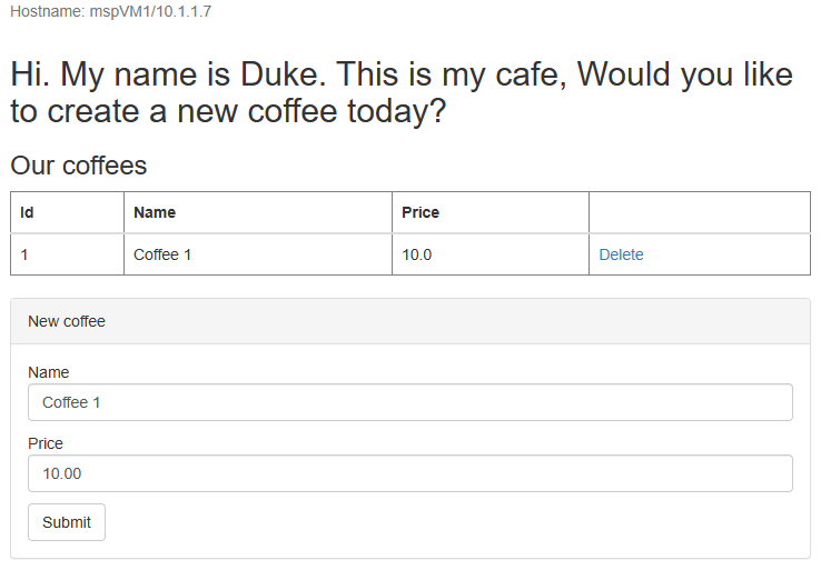
Open the DNS name of your Azure Traffic Manager profile in a new tab of the browser, appending the context root /weblogic-cafe of the deployed app - for example, http://tmprofile-ejb120623.trafficmanager.net/weblogic-cafe. Create a new coffee with name and price - for example, Coffee 1 with price 10. This entry is persisted into both the application data table and the session table of the database. The UI that you see should be similar to the following screenshot:

If your UI doesn't look similar, troubleshoot and resolve the problem before you continue.
Keep the page open so you can use it for failover testing later.
Test failover from primary to secondary
To test failover, you manually fail your primary database server and cluster over to the secondary database server and cluster, and then fail back using the Azure portal in this section.
Failover to the secondary site
First, use the following steps to shut down the VMs in the primary cluster:
- Find the name of your resource group where the primary WLS cluster is deployed - for example, wls-cluster-eastus-ejb120623. Then follow the steps in the Stop VMs in the secondary cluster section, but change the target resource group to your primary WLS cluster, to stop all VMs in that cluster.
- Switch to the browser tab of your Traffic Manager, refresh the page until you see that the Monitor status value of the endpoint myPrimaryEndpoint becomes Degraded.
- Switch to the browser tab of the sample app and refresh the page. You should see 504 Gateway Time-out or 502 Bad Gateway because none of endpoints is accessible.
Next, use the following steps to failover the Azure SQL Database from the primary server to the secondary server:
- Switch to the browser tab of your Azure SQL Database failover group.
- Select Failover > Yes.
- Wait until it completes.
Then, use the following steps to start all servers in the secondary cluster:
- Switch to the browser tab where you stopped all the VMs in the secondary cluster.
- Select the VM
adminVM. Select Start. - Monitor the event Starting virtual machine for
adminVMin the Notifications pane, and wait until the value becomes Started virtual machine. - Switch to the browser tab of the WebLogic Server Administration Console for the secondary cluster, then refresh the page until you see the welcome page for sign in.
- Switch back to the browser tab where all the VMs in the secondary cluster are listed. For the VMs
mspVM1,mspVM2, andmspVM3, select each one to open it and then select Start. - For the VMs
mspVM1,mspVM2, andmspVM3, monitor the event Starting virtual machine in the Notifications pane, and wait until the values become Started virtual machine.
Finally, use the following steps to verify the sample app after the endpoint myFailoverEndpoint is in the Online state:
Switch to the browser tab of your Traffic Manager, then refresh the page until you see that the Monitor status value of the endpoint
myFailoverEndpointenters the Online state.Switch to the browser tab of the sample app and refresh the page. You should see the same data persisted in the application data table and the session table displayed in the UI, as shown in the following screenshot:
If you don't observe this behavior, it might be because the Traffic Manager is taking time to update DNS to point to the failover site. The problem could also be that your browser cached the DNS name resolution result that points to the failed site. Wait for a while and refresh the page again.
Note
A production-ready HA/DR solution would account for continually copying the WLS configuration from the primary to the secondary clusters on a regular schedule. For information on how to do this, see the references to the Oracle documentation at the end of this article.
To automate the failover, consider using alerts on Traffic Manager metrics and Azure Automation. For more information, see the Alerts on Traffic Manager metrics section of Traffic Manager metrics and alerts and Use an alert to trigger an Azure Automation runbook.
Fail back to the primary site
Use the same steps in the Failover to the secondary site section to fail back to the primary site including database server and cluster, except for the following differences:
- First, shut down the VMs in the secondary cluster. You should see that endpoint myFailoverEndpoint becomes Degraded.
- Next, failover the Azure SQL Database from the secondary server to the primary server.
- Then, start all servers in the primary cluster.
- Finally, verify the sample app after the endpoint myPrimaryEndpoint is Online.
Clean up resources
If you're not going to continue to use the WLS clusters and other components, use the following steps to delete the resource groups to clean up the resources used in this tutorial:
- Enter the resource group name of Azure SQL Database servers - for example,
myResourceGroup- in the search box at the top of the Azure portal, and select the matched resource group from the search results. - Select Delete resource group.
- In Enter resource group name to confirm deletion, enter the resource group name.
- Select Delete.
- Repeat steps 1-4 for the resource group of the Traffic Manager - for example,
myResourceGroupTM1. - Repeat steps 1-4 for the resource group of the primary WLS cluster - for example,
wls-cluster-eastus-ejb120623. - Repeat steps 1-4 for the resource group of the secondary WLS cluster - for example,
wls-cluster-westus-ejb120623.
Next steps
In this tutorial, you set up an HA/DR solution consisting of an active-passive application infrastructure tier with an active-passive database tier, and in which both tiers span two geographically different sites. At the first site, both the application infrastructure tier and the database tier are active. At the second site, the secondary domain is shut down, and the secondary database is on standby.
Continue to explore the following references for more options to build HA/DR solutions and run WLS on Azure: