Note
Access to this page requires authorization. You can try signing in or changing directories.
Access to this page requires authorization. You can try changing directories.
At the core of IoT Plug and Play, is a device model that describes a device's capabilities to an IoT Plug and Play-enabled application. This model is structured as a set of interfaces that define:
- Properties that represent the read-only or writable state of a device or other entity. For example, a device serial number may be a read-only property and a target temperature on a thermostat may be a writable property.
- Telemetry fields that define the data emitted by a device, whether the data is a regular stream of sensor readings, an occasional error, or an information message.
- Commands that describe a function or operation that can be done on a device. For example, a command could reboot a gateway or take a picture using a remote camera.
To learn more about how IoT Plug and Play uses device models, see IoT Plug and Play device developer guide and IoT Plug and Play service developer guide.
To define a model, you use the Digital Twins Definition Language (DTDL). DTDL uses a JSON variant called JSON-LD. The following snippet shows the model for a thermostat device that:
- Has a unique model ID:
dtmi:com:example:Thermostat;1. - Sends temperature telemetry.
- Has a writable property to set the target temperature.
- Has a read-only property to report the maximum temperature since the last reboot.
- Responds to a command that requests maximum, minimum and average temperatures over a time period.
{
  "@context": "dtmi:dtdl:context;2",
  "@id": "dtmi:com:example:Thermostat;1",
  "@type": "Interface",
  "displayName": "Thermostat",
  "description": "Reports current temperature and provides desired temperature control.",
  "contents": [
    {
      "@type": [
        "Telemetry",
        "Temperature"
      ],
      "name": "temperature",
      "displayName": "Temperature",
      "description": "Temperature in degrees Celsius.",
      "schema": "double",
      "unit": "degreeCelsius"
    },
    {
      "@type": [
        "Property",
        "Temperature"
      ],
      "name": "targetTemperature",
      "schema": "double",
      "displayName": "Target Temperature",
      "description": "Allows to remotely specify the desired target temperature.",
      "unit": "degreeCelsius",
      "writable": true
    },
    {
      "@type": [
        "Property",
        "Temperature"
      ],
      "name": "maxTempSinceLastReboot",
      "schema": "double",
      "unit": "degreeCelsius",
      "displayName": "Max temperature since last reboot.",
      "description": "Returns the max temperature since last device reboot."
    },
    {
      "@type": "Command",
      "name": "getMaxMinReport",
      "displayName": "Get Max-Min report.",
      "description": "This command returns the max, min and average temperature from the specified time to the current time.",
      "request": {
        "name": "since",
        "displayName": "Since",
        "description": "Period to return the max-min report.",
        "schema": "dateTime"
      },
      "response": {
        "name": "tempReport",
        "displayName": "Temperature Report",
        "schema": {
          "@type": "Object",
          "fields": [
            {
              "name": "maxTemp",
              "displayName": "Max temperature",
              "schema": "double"
            },
            {
              "name": "minTemp",
              "displayName": "Min temperature",
              "schema": "double"
            },
            {
              "name": "avgTemp",
              "displayName": "Average Temperature",
              "schema": "double"
            },
            {
              "name": "startTime",
              "displayName": "Start Time",
              "schema": "dateTime"
            },
            {
              "name": "endTime",
              "displayName": "End Time",
              "schema": "dateTime"
            }
          ]
        }
      }
    }
  ]
}
The thermostat model has a single interface. Later examples in this article show more complex models that use components and inheritance.
This article describes how to design and author your own models and covers topics such as data types, model structure, and tools.
To learn more, see the Digital Twins Definition Language specification.
Note
IoT Central currently supports DTDL v2 with an IoT Central extension.
Model structure
Properties, telemetry, and commands are grouped into interfaces. This section describes how you can use interfaces to describe simple and complex models by using components and inheritance.
Model IDs
Every interface has a unique digital twin model identifier (DTMI). Complex models use DTMIs to identify components. Applications can use the DTMIs that devices send to locate model definitions in a repository.
DTMIs should use the following the naming convention:
- The DTMI prefix is
dtmi:. - The DTMI suffix is version number for the model such as
;2. - The body of the DTMI maps to the folder and file in the model repository where the model is stored. The version number is part of the file name.
For example, the model identified by the DTMI dtmi:com:Example:Thermostat;2 is stored in the dtmi/com/example/thermostat-2.json file.
The following snippet shows the outline of an interface definition with its unique DTMI:
{
  "@context": "dtmi:dtdl:context;2",
  "@id": "dtmi:com:example:Thermostat;2",
  "@type": "Interface",
  "displayName": "Thermostat",
  "description": "Reports current temperature and provides desired temperature control.",
  "contents": [
    ...
  ]
}
No components
A simple model, such as the thermostat shown previously, doesn't use embedded or cascaded components. Telemetry, properties, and commands are defined in the contents node of the interface.
The following example shows part of a simple model that doesn't use components:
{
  "@context": "dtmi:dtdl:context;2",
  "@id": "dtmi:com:example:Thermostat;1",
  "@type": "Interface",
  "displayName": "Thermostat",
  "description": "Reports current temperature and provides desired temperature control.",
  "contents": [
    {
      "@type": [
        "Telemetry",
        "Temperature"
      ],
      "name": "temperature",
      "displayName": "Temperature",
      "description": "Temperature in degrees Celsius.",
      "schema": "double",
      "unit": "degreeCelsius"
    },
    {
      "@type": [
        "Property",
...
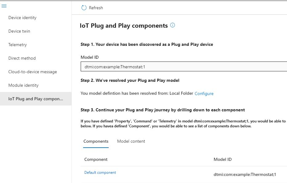
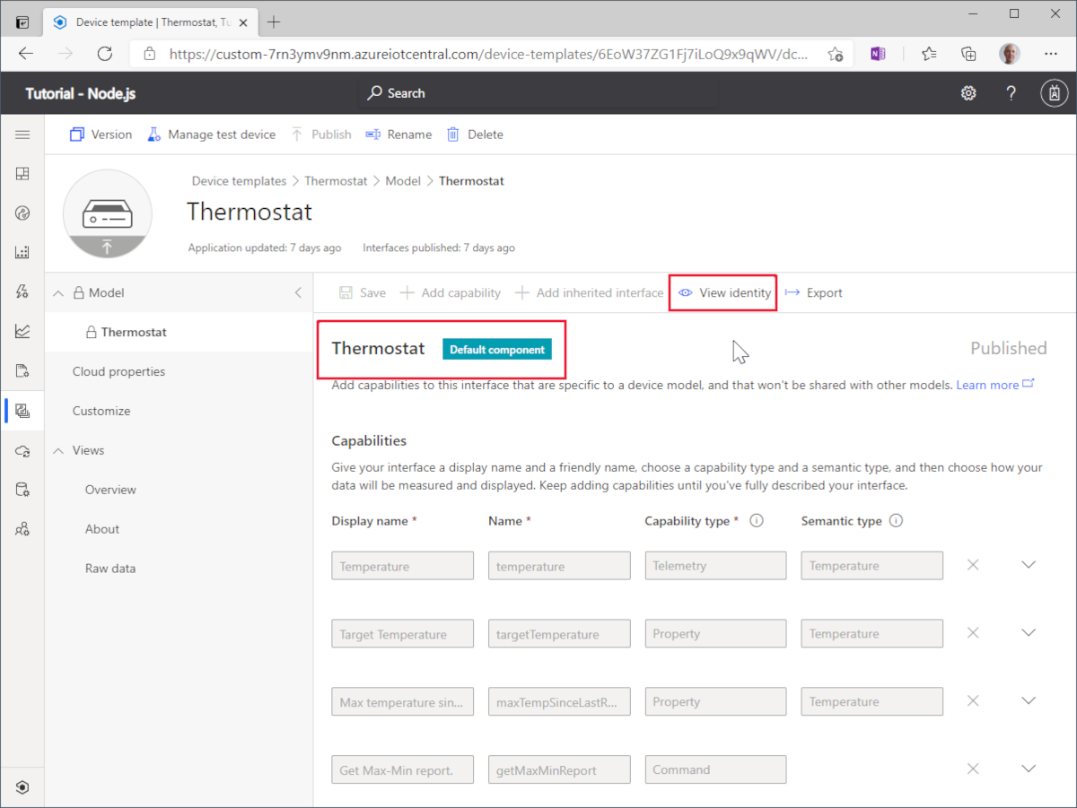
Tools such as Azure IoT Explorer and the IoT Central device template designer label a standalone interface like the thermostat as a default component.
The following screenshot shows how the model displays in the Azure IoT Explorer tool:
The following screenshot shows how the model displays as the default component in the IoT Central device template designer. Select View identity to see the DTMI of the model:
The model ID is stored in a device twin property as the following screenshot shows:

A DTDL model without components is a useful simplification for a device or an IoT Edge module with a single set of telemetry, properties, and commands. A model that doesn't use components makes it easy to migrate an existing device or module to be an IoT Plug and Play device or module - you create a DTDL model that describes your actual device or module without the need to define any components.
Tip
A module can be a device module or an IoT Edge module.
Reuse
There are two ways to reuse interface definitions.
- Use multiple components in a model to reference other interface definitions.
- Use inheritance to extend existing interface definitions.
Multiple components
Components let you build a model interface as an assembly of other interfaces.
For example, the Thermostat interface is defined as a model. You can incorporate this interface as one or more components when you define the Temperature Controller model. In the following example, these components are called thermostat1 and thermostat2.
For a DTDL model with multiple components, there are two or more component sections. Each section has @type set to Component and explicitly refers to a schema as shown in the following snippet:
{
  "@context": "dtmi:dtdl:context;2",
  "@id": "dtmi:com:example:TemperatureController;1",
  "@type": "Interface",
  "displayName": "Temperature Controller",
  "description": "Device with two thermostats and remote reboot.",
  "contents": [
    {
      "@type": [
        "Telemetry",
        "DataSize"
      ],
      "name": "workingSet",
      "displayName": "Working Set",
      "description": "Current working set of the device memory in KiB.",
      "schema": "double",
      "unit": "kibibyte"
    },
    {
      "@type": "Property",
      "name": "serialNumber",
      "displayName": "Serial Number",
      "description": "Serial number of the device.",
      "schema": "string"
    },
    {
      "@type": "Command",
      "name": "reboot",
      "displayName": "Reboot",
      "description": "Reboots the device after waiting the number of seconds specified.",
      "request": {
        "name": "delay",
        "displayName": "Delay",
        "description": "Number of seconds to wait before rebooting the device.",
        "schema": "integer"
      }
    },
    {
      "@type" : "Component",
      "schema": "dtmi:com:example:Thermostat;1",
      "name": "thermostat1",
      "displayName": "Thermostat One",
      "description": "Thermostat One of Two."
    },
    {
      "@type" : "Component",
      "schema": "dtmi:com:example:Thermostat;1",
      "name": "thermostat2",
      "displayName": "Thermostat Two",
      "description": "Thermostat Two of Two."
    },
    {
      "@type": "Component",
      "schema": "dtmi:azure:DeviceManagement:DeviceInformation;1",
      "name": "deviceInformation",
      "displayName": "Device Information interface",
      "description": "Optional interface with basic device hardware information."
    }
  ]
}
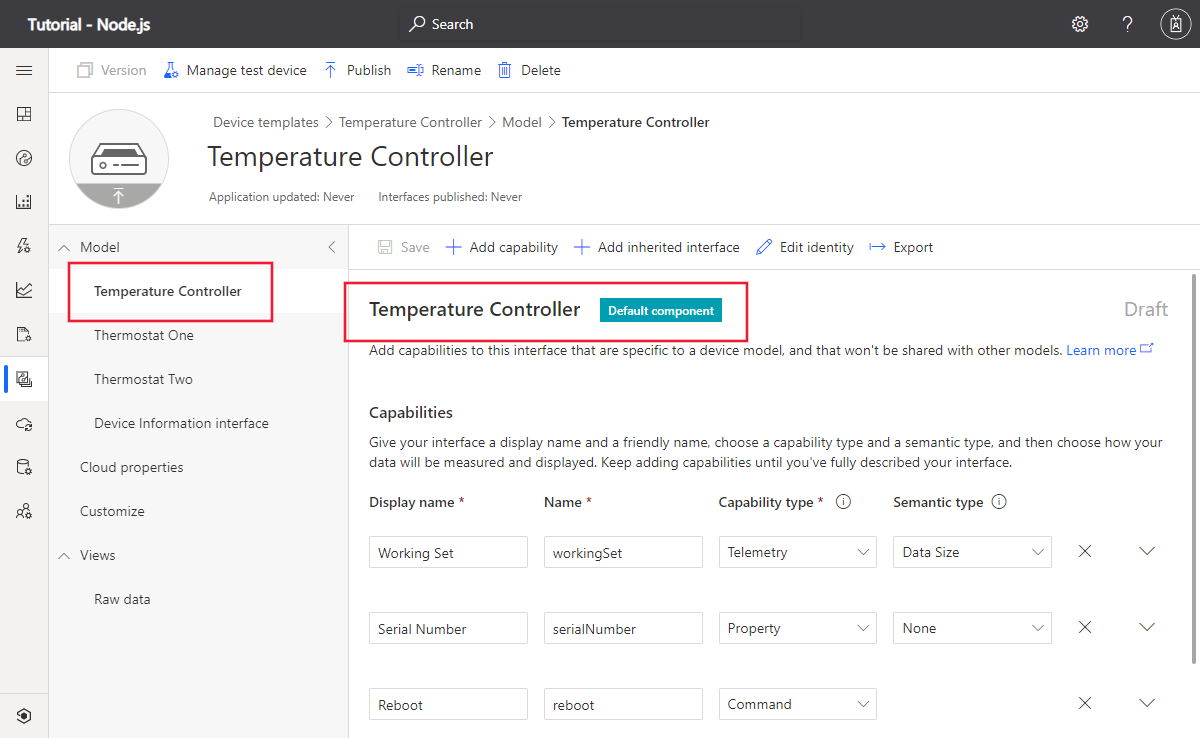
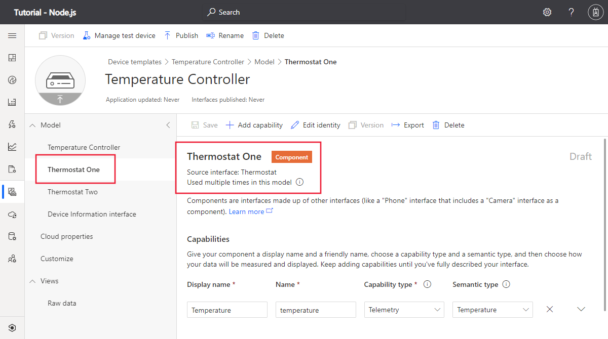
This model has three components defined in the contents section - two Thermostat components and a DeviceInformation component. The contents section also includes property, telemetry, and command definitions.
The following screenshots show how this model appears in IoT Central. The property, telemetry, and command definitions in the temperature controller appear in the top-level Default component. The property, telemetry, and command definitions for each thermostat appear in the component definitions:
To learn how to write device code that interacts with components, see IoT Plug and Play device developer guide.
To learn how to write service code that interacts with components on a device, see IoT Plug and Play service developer guide.
Inheritance
Inheritance lets you reuse capabilities in a base interfaces to extend the capabilities of an interface. For example, several device models can share common capabilities such as a serial number:
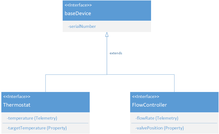
The following snippet shows a DTML model that uses the extends keyword to define the inheritance relationship shown in the previous diagram:
[
  {
    "@context": "dtmi:dtdl:context;2",
    "@id": "dtmi:com:example:Thermostat;1",
    "@type": "Interface",
    "contents": [
      {
        "@type": "Telemetry",
        "name": "temperature",
        "schema": "double",
        "unit": "degreeCelsius"
      },
      {
        "@type": "Property",
        "name": "targetTemperature",
        "schema": "double",
        "unit": "degreeCelsius",
        "writable": true
      }
    ],
    "extends": [
      "dtmi:com:example:baseDevice;1"
    ]
  },
  {
    "@context": "dtmi:dtdl:context;2",
    "@id": "dtmi:com:example:baseDevice;1",
    "@type": "Interface",
    "contents": [
      {
        "@type": "Property",
        "name": "SerialNumber",
        "schema": "double",
        "writable": false
      }
    ]
  }
]
The following screenshot shows this model in the IoT Central device template environment:
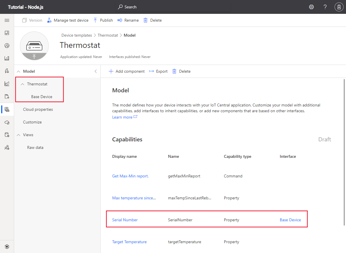
When you write device or service-side code, your code doesn't need to do anything special to handle inherited interfaces. In the example shown in this section, your device code reports the serial number as if it's part of the thermostat interface.
Tips
You can combine components and inheritance when you create a model. The following diagram shows a thermostat model inheriting from a baseDevice interface. The baseDevice interface has a component, that itself inherits from another interface:
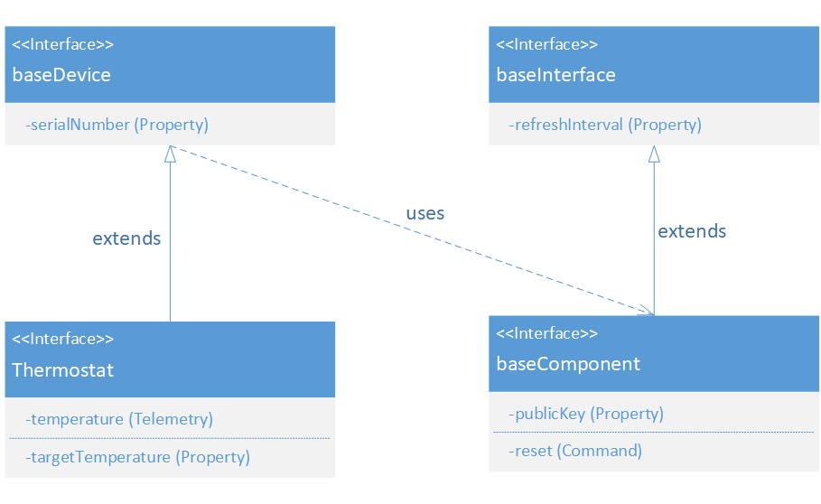
The following snippet shows a DTML model that uses the extends and component keywords to define the inheritance relationship and component usage shown in the previous diagram:
[
  {
    "@context": "dtmi:dtdl:context;2",
    "@id": "dtmi:com:example:Thermostat;1",
    "@type": "Interface",
    "contents": [
      {
        "@type": "Telemetry",
        "name": "temperature",
        "schema": "double",
        "unit": "degreeCelsius"
      },
      {
        "@type": "Property",
        "name": "targetTemperature",
        "schema": "double",
        "unit": "degreeCelsius",
        "writable": true
      }
    ],
    "extends": [
      "dtmi:com:example:baseDevice;1"
    ]
  },
  {
    "@context": "dtmi:dtdl:context;2",
    "@id": "dtmi:com:example:baseDevice;1",
    "@type": "Interface",
    "contents": [
      {
        "@type": "Property",
        "name": "SerialNumber",
        "schema": "double",
        "writable": false
      },
      {
        "@type" : "Component",
        "schema": "dtmi:com:example:baseComponent;1",
        "name": "baseComponent"
      }
    ]
  }
]
Data types
Use data types to define telemetry, properties, and command parameters. Data types can be primitive or complex. Complex data types use primitives or other complex types. The maximum depth for complex types is five levels.
Primitive types
The following table shows the set of primitive types you can use:
| Primitive type | Description |
|---|---|
boolean |
A boolean value |
date |
A full-date as defined in section 5.6 of RFC 3339 |
dateTime |
A date-time as defined in RFC 3339 |
double |
An IEEE 8-byte floating point |
duration |
A duration in ISO 8601 format |
float |
An IEEE 4-byte floating point |
integer |
A signed 4-byte integer |
long |
A signed 8-byte integer |
string |
A UTF8 string |
time |
A full-time as defined in section 5.6 of RFC 3339 |
The following snippet shows an example telemetry definition that uses the double type in the schema field:
{
  "@type": "Telemetry",
  "name": "temperature",
  "displayName": "Temperature",
  "schema": "double"
}
Complex data types
Complex data types are one of array, enumeration, map, object, or one of the geospatial types.
Arrays
An array is an indexable data type where all elements are the same type. The element type can be a primitive or complex type.
The following snippet shows an example telemetry definition that uses the Array type in the schema field. The elements of the array are booleans:
{
  "@type": "Telemetry",
  "name": "ledState",
  "schema": {
    "@type": "Array",
    "elementSchema": "boolean"
  }
}
Enumerations
An enumeration describes a type with a set of named labels that map to values. The values can be either integers or strings, but the labels are always strings.
The following snippet shows an example telemetry definition that uses the Enum type in the schema field. The values in the enumeration are integers:
{
  "@type": "Telemetry",
  "name": "state",
  "schema": {
    "@type": "Enum",
    "valueSchema": "integer",
    "enumValues": [
      {
        "name": "offline",
        "displayName": "Offline",
        "enumValue": 1
      },
      {
        "name": "online",
        "displayName": "Online",
        "enumValue": 2
      }
    ]
  }
}
Maps
A map is a type with key-value pairs where the values all have the same type. The key in a map must be a string. The values in a map can be any type, including another complex type.
The following snippet shows an example property definition that uses the Map type in the schema field. The values in the map are strings:
{
  "@type": "Property",
  "name": "modules",
  "writable": true,
  "schema": {
    "@type": "Map",
    "mapKey": {
      "name": "moduleName",
      "schema": "string"
    },
    "mapValue": {
      "name": "moduleState",
      "schema": "string"
    }
  }
}
Objects
An object type is made up of named fields. The types of the fields in an object map can be primitive or complex types.
The following snippet shows an example telemetry definition that uses the Object type in the schema field. The fields in the object are dateTime, duration, and string types:
{
  "@type": "Telemetry",
  "name": "monitor",
  "schema": {
    "@type": "Object",
    "fields": [
      {
        "name": "start",
        "schema": "dateTime"
      },
      {
        "name": "interval",
        "schema": "duration"
      },
      {
        "name": "status",
        "schema": "string"
      }
    ]
  }
}
Geospatial types
DTDL provides a set of geospatial types, based on GeoJSON, for modeling geographic data structures: point, multiPoint, lineString, multiLineString, polygon, and multiPolygon. These types are predefined nested structures of arrays, objects, and enumerations.
The following snippet shows an example telemetry definition that uses the point type in the schema field:
{
  "@type": "Telemetry",
  "name": "location",
  "schema": "point"
}
Because the geospatial types are array-based, they can't currently be used in property definitions.
Semantic types
The data type of a property or telemetry definition specifies the format of the data that a device exchanges with a service. The semantic type provides information about telemetry and properties that an application can use to determine how to process or display a value. Each semantic type has one or more associated units. For example, celsius and fahrenheit are units for the temperature semantic type. IoT Central dashboards and analytics can use the semantic type information to determine how to plot telemetry or property values and display units. To learn how you can use the model parser to read the semantic types, see Understand the Digital Twins model parser.
The following snippet shows an example telemetry definition that includes semantic type information. The semantic type Temperature is added to the @type array, and the unit value, degreeCelsius is one of the valid units for the semantic type:
{
  "@type": [
    "Telemetry",
    "Temperature"
  ],
  "name": "temperature",
  "schema": "double",
  "unit": "degreeCelsius"
}
Localization
Applications, such as IoT Central, use information in the model to dynamically build a UI around the data exchanged with an IoT Plug and Play device. For example, tiles on a dashboard can display names and descriptions for telemetry, properties, and commands.
The optional description and displayName fields in the model hold strings intended for use in a UI. These fields can hold localized strings that an application can use to render a localized UI.
The following snippet shows an example temperature telemetry definition that includes localized strings:
{
  "@type": [
    "Telemetry",
    "Temperature"
  ],
  "description": {
    "en": "Temperature in degrees Celsius.",
    "it": "Temperatura in gradi Celsius."
  },
  "displayName": {
    "en": "Temperature",
    "it": "Temperatura"
  },
  "name": "temperature",
  "schema": "double",
  "unit": "degreeCelsius"
}
Adding localized strings is optional. The following example has only a single, default language:
{
  "@type": [
    "Telemetry",
    "Temperature"
  ],
  "description": "Temperature in degrees Celsius.",
  "displayName": "Temperature",
  "name": "temperature",
  "schema": "double",
  "unit": "degreeCelsius"
}
Lifecycle and tools
The four lifecycle stages for a device model are author, publish, use, and version:
Author
DTML device models are JSON documents that you can create in a text editor. However, in IoT Central you can use the device template GUI environment to create a DTML model. In IoT Central you can:
- Create interfaces that define properties, telemetry, and commands.
- Use components to assemble multiple interfaces together.
- Define inheritance relationships between interfaces.
- Import and export DTML model files.
To learn more, see Define a new IoT device type in your Azure IoT Central application.
There's a DTDL authoring extension for VS Code that supports both DTDL v2 and DTDL v3.
To install the DTDL extension for VS Code, go to DTDL editor for Visual Studio Code. You can also search for DTDL in the Extensions view in VS Code.
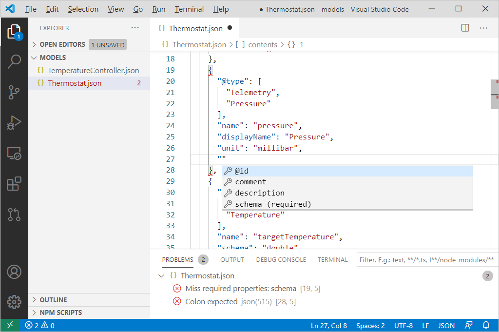
After you install the extension, use it to help you author DTDL model files in VS Code:
The extension provides syntax validation in DTDL model files, highlighting errors as shown on the following screenshot:
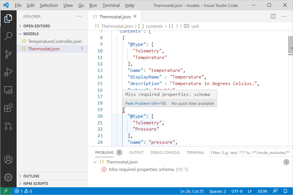
Use intellisense and autocomplete when you're editing DTDL models:
Create a new DTDL interface. The DTDL: Create Interface command creates a JSON file with a new interface. The interface includes example telemetry, property, and command definitions.
Use
Applications, such as IoT Central, use device models. In IoT Central, a model is part of the device template that describes the capabilities of the device. IoT Central uses the device template to dynamically build a UI for the device, including dashboards and analytics.
Note
IoT Central defines some extensions to the DTDL language. To learn more, see IoT Central extension.
A custom solution can use the Digital Twins model parser to understand the capabilities of a device that implements the model. To learn more, see Use IoT Plug and Play models in an IoT solution.
Version
To ensure devices and server-side solutions that use models continue to work, published models are immutable.
The DTMI includes a version number that you can use to create multiple versions of a model. Devices and server-side solutions can use the specific version they were designed to use.
IoT Central implements more versioning rules for device models. If you version a device template and its model in IoT Central, you can migrate devices from previous versions to later versions. However, migrated devices can't use new capabilities without a firmware upgrade. To learn more, see Edit a device template.
Publish
As of February 2024, the Azure Certified Device program is retired. Therefore, Microsoft is no longer accepting submissions of DTDL models to the Azure IoT plug and play models repository.
If you want to set up your own model repository, you can use the Azure IoT plug and play models tools repository. This repository includes the code for the dmr-client CLI tool that can validate, import, and expand DTDL models. This tool also lets you index model repositories that follow the device model repository conventions.
Limits and constraints
The following list summarizes some key constraints and limits on models:
- Currently, the maximum depth for arrays, maps, and objects is five levels.
- You can't use arrays in property definitions.
- You can extend interfaces to a depth of 10 levels.
- An interface can extend at most two other interfaces.
- A component can't contain another component.
Understand the Digital Twins model parser
The Digital Twins Definition Language (DTDL) is described in the DTDL Specification. Users can use the Digital Twins Model Parser NuGet package to validate and query a DTDL v2 or v3 model. The DTDL model can be defined in multiple files.
Install the DTDL model parser
The parser is available in NuGet.org with the ID: DTDLParser. To install the parser, use any compatible NuGet package manager such as the one in Visual Studio or in the dotnet CLI.
dotnet add package DTDLParser
Note
At the time of writing, the parser version is 1.0.52.
Use the parser to validate and inspect a model
The DTDLParser is a library that you can use to:
- Determine whether one or more models are valid according to the language v2 or v3 specifications.
- Identify specific modeling errors.
- Inspect model contents.
A model can be composed of one or more interfaces described in JSON files. You can use the parser to load all the files that define a model and then validate all the files as a whole, including any references between the files.
The DTDLParser for .NET repository includes the following samples that illustrate the use of the parser:
- DTDLParserResolveSample shows how to parse an interface with external references, resolve the dependencies using the
Azure.IoT.ModelsRepositoryclient. - DTDLParserJSInteropSample shows how to use the DTDL Parser from JavaScript running in the browser, using .NET JSInterop.
The DTDLParser for .NET repository also includes a collection of tutorials that show you how to use the parser to validate and inspect models.
The model parser API enables many scenarios to automate or validate tasks that depend on DTDL models. For example, you could dynamically build a UI from the information in the model.
Next steps
Now that you learned about device modeling, here are some more resources: