Note
Access to this page requires authorization. You can try signing in or changing directories.
Access to this page requires authorization. You can try changing directories.
To host multiple websites, you can use another network interface associated with a virtual machine. Azure Load Balancer supports deployment of load-balancing to support the high availability of the websites.
In this tutorial, you learn how to:
- Create and configure a virtual network, subnet, and NAT gateway.
- Create two Windows server virtual machines
- Create a secondary NIC and network configurations for each virtual machine
- Create two Internet Information Server (IIS) websites on each virtual machine
- Bind the websites to the network configurations
- Create and configure an Azure Load Balancer
- Test the load balancer
Prerequisites
- An Azure account with an active subscription. Create an account for free.
Create a virtual network and bastion host
In this section, you create a virtual network with a resource subnet, an Azure Bastion subnet, and an Azure Bastion host.
Important
Hourly pricing starts from the moment that Bastion is deployed, regardless of outbound data usage. For more information, see Pricing and SKUs. If you're deploying Bastion as part of a tutorial or test, we recommend that you delete this resource after you finish using it.
In the portal, search for and select Virtual networks.
On the Virtual networks page, select + Create.
On the Basics tab of Create virtual network, enter or select the following information:
Setting Value Project details Subscription Select your subscription. Resource group Select load-balancer-rg from the dropdown or Create new if it doesn't exist.
Enter load-balancer-rg in Name.
Select OK.Instance details Name Enter lb-vnet. Region Select (US) East US. Select the Security tab or Next button at the bottom of the page.
Under Azure Bastion, enter or select the following information:
Setting Value Azure Bastion Enable Azure Bastion Select checkbox. Azure Bastion host name Enter lb-vnet-bastion. Azure Bastion public IP address Select Create new.
Enter lb-vnet-bastion-ip in Name.
Select OK.Select the IP addresses tab, or Next at the bottom of the page.
On Create virtual network page, enter or select the following information:
Setting Value IPv4 address space Enter 10.0.0.0/16 (65,356 addresses). Subnets Select the default subnet link to edit. Edit subnet Subnet purpose Leave the default Default. Name Enter backend-subnet. Starting address Enter 10.0.0.0. Subnet size Enter /24(256 addresses). Security NAT Gateway Select lb-nat-gateway. Select Save.
Select Review + create at the bottom of the screen, and when validation passes, select Create.
Important
Hourly pricing starts from the moment that Bastion is deployed, regardless of outbound data usage. For more information, see Pricing and SKUs. If you're deploying Bastion as part of a tutorial or test, we recommend that you delete this resource after you finish using it.
Create NAT gateway
In this section, you create a NAT gateway for outbound internet access for resources in the virtual network. For other options for outbound rules, check out Network Address Translation (SNAT) for outbound connections
In the search box at the top of the portal, enter NAT gateway. Select NAT gateways in the search results.
Select + Create.
In the Basics tab of Create network address translation (NAT) gateway enter or select the following information:
Setting Value Project details Subscription Select your subscription. Resource group Select Create a new resource group.
Enter load-balancer-rg in Name.
Select OK.Instance details NAT gateway name Enter lb-nat-gateway. Region Select East US. SKU Select Standard. Availability zone Select None. TCP idle timeout (minutes) Enter 15. Select the Outbound IP tab or select the Next button at the bottom of the page.
Select Add public IP addresses or prefixes.
On the Manage public IP addresses and prefixes page, select Create a public IP address and enter nat-gw-public-ip in Name.
Select OK and Save.
Select the blue Review + create button at the bottom of the page, or select the Review + create tab.
Select Create.
Create virtual machines
In this section, you create two virtual machines to host the IIS websites.
In the search box at the top of the portal, enter Virtual machine. Select Virtual machines in the search results.
In Virtual machines, select + Create then Azure virtual machine.
In Create virtual machine, enter or select the following information:
Setting Value Project Details Subscription Select your Azure subscription Resource Group Select load-balancer-rg Instance details Virtual machine name Enter myVM1 Region Select (US) East US Availability Options Select Availability zones Availability zone Select 1 Security type Leave the default of Standard. Image Select Windows Server 2022 Datacenter - Gen2 Size Choose VM size or take default setting Administrator account Username Enter a username Password Enter a password Confirm password Reenter password Inbound port rules Public inbound ports Select None Select the Networking tab, or select Next: Disks, then Next: Networking.
In the Networking tab, select or enter:
Setting Value Network interface Virtual network Select myVNet. Subnet Select backend-subnet(10.1.0.0/24) Public IP Select None. NIC network security group Select Advanced Configure network security group Select Create new.
In Create network security group, enter myNSG in Name.
In Inbound rules, select +Add an inbound rule.
In Service, select HTTP.
In Priority, enter 100.
In Name, enter myNSGrule.
Select Add.
Select OK.Select Review + create.
Review the settings, and then select Create.
Follow the steps 1 to 7 to create another VM with the following values and all the other settings the same as myVM1:
Setting VM 2 Name myVM2 Availability zone 2 Network security group Select the existing myNSG
Note
Azure provides a default outbound access IP for VMs that either aren't assigned a public IP address or are in the backend pool of an internal basic Azure load balancer. The default outbound access IP mechanism provides an outbound IP address that isn't configurable.
The default outbound access IP is disabled when one of the following events happens:
- A public IP address is assigned to the VM.
- The VM is placed in the backend pool of a standard load balancer, with or without outbound rules.
- An Azure NAT Gateway resource is assigned to the subnet of the VM.
VMs that you create by using virtual machine scale sets in flexible orchestration mode don't have default outbound access.
For more information about outbound connections in Azure, see Default outbound access in Azure and Use Source Network Address Translation (SNAT) for outbound connections.
Create secondary network configurations
In this section, you change the private IP address of the existing NIC of each virtual machine to Static. Next, you add a new NIC resource to each virtual machine with a Static private IP address configuration.
For more information on configuring floating IP in the virtual machine configuration, see Floating IP Guest OS configuration.
In the search box at the top of the portal, enter Virtual machine. Select Virtual machines in the search results.
Select myVM1.
Stop the virtual machine if it's running.
Select Networking in Settings.
In Networking, select the name of the network interface next to Network interface. The network interface begins with the name of the VM and has a random number assigned. In this example, myVM1266.
In the network interface page, select IP configurations in Settings.
In IP configurations, select ipconfig1.
Select Static in Assignment in the ipconfig1 configuration.
Select Save.
Return to the Overview page of myVM1.
Select Networking in Settings.
In the Networking page, select Attach network interface.
In Attach network interface, select Create and attach network interface.
In Create network interface, enter or select the following information:
Setting Value Project details Resource group Select load-balancer-rg. Network interface Name Enter myVM1NIC2 Subnet Select backend-subnet (10.1.0.0/24). NIC network security group Select Advanced. Configure network security group Select myNSG. Private IP address assignment Select Static. Private IP address Enter 10.1.0.6. Select Create.
Start the virtual machine.
Repeat steps 1 through 16 for myVM2, replacing the following information:
Setting myVM2 Name myVM2NIC2 Private IP address 10.1.0.7
Configure virtual machines
You connect to myVM1 and myVM2 with Azure Bastion and configure the secondary network configuration in this section. You add a route for the gateway for the secondary network configuration. Then you install IIS on each virtual machine and customize the websites to display the hostname of the virtual machine.
In the search box at the top of the portal, enter Virtual machine. Select Virtual machines in the search results.
Select myVM1.
Start myVM1.
In Overview, select Connect then Bastion.
Enter the username and password you entered when you created the virtual machine.
Select Allow for Bastion to use the clipboard.
On the server desktop, navigate to Start > Windows Administrative Tools > Windows PowerShell > Windows PowerShell.
In the PowerShell window, execute the
route printcommand, which returns output similar to the following output for a virtual machine with two attached network interfaces:=========================================================================== Interface List 4...60 45 bd 9c c7 00 ......Microsoft Hyper-V Network Adapter 11...60 45 bd 8d 44 fa ......Microsoft Hyper-V Network Adapter #3 1...........................Software Loopback Interface 1 =========================================================================== IPv4 Route Table =========================================================================== Active Routes: Network Destination Netmask Gateway Interface Metric 0.0.0.0 0.0.0.0 10.1.0.1 10.1.0.4 10 10.1.0.0 255.255.255.0 On-link 10.1.0.4 266 10.1.0.0 255.255.255.0 On-link 10.1.0.6 266 10.1.0.4 255.255.255.255 On-link 10.1.0.4 266 10.1.0.6 255.255.255.255 On-link 10.1.0.6 266 10.1.0.255 255.255.255.255 On-link 10.1.0.4 266 10.1.0.255 255.255.255.255 On-link 10.1.0.6 266 127.0.0.0 255.0.0.0 On-link 127.0.0.1 331 127.0.0.1 255.255.255.255 On-link 127.0.0.1 331 127.255.255.255 255.255.255.255 On-link 127.0.0.1 331 168.63.129.16 255.255.255.255 10.1.0.1 10.1.0.4 11 169.254.169.254 255.255.255.255 10.1.0.1 10.1.0.4 11 224.0.0.0 240.0.0.0 On-link 127.0.0.1 331 224.0.0.0 240.0.0.0 On-link 10.1.0.4 266 224.0.0.0 240.0.0.0 On-link 10.1.0.6 266 255.255.255.255 255.255.255.255 On-link 127.0.0.1 331 255.255.255.255 255.255.255.255 On-link 10.1.0.4 266 255.255.255.255 255.255.255.255 On-link 10.1.0.6 266 =========================================================================== Persistent Routes: None IPv6 Route Table =========================================================================== Active Routes: If Metric Network Destination Gateway 1 331 ::1/128 On-link 4 266 fe80::/64 On-link 11 266 fe80::/64 On-link 11 266 fe80::382:8783:5d2:f71e/128 On-link 4 266 fe80::1575:ced8:3e94:f23a/128 On-link 1 331 ff00::/8 On-link 4 266 ff00::/8 On-link 11 266 ff00::/8 On-link =========================================================================== Persistent Routes: NoneIn this example, Microsoft Hyper-V Network Adapter #3 (interface 13) is the secondary network interface that doesn't have a default gateway assigned to it.
In the PowerShell window, execute the
ipconfig /allcommand to see which IP address is assigned to the secondary network interface. In this example, 10.1.0.6 is assigned to interface 13. No default gateway address is returned for the secondary network interface.Connection-specific DNS Suffix . : pbu0t5vjr3sevaritkncspakhd.ax.internal.cloudapp.net Description . . . . . . . . . . . : Microsoft Hyper-V Network Adapter #3 Physical Address. . . . . . . . . : 60-45-BD-A1-75-FB DHCP Enabled. . . . . . . . . . . : Yes Autoconfiguration Enabled . . . . : Yes Link-local IPv6 Address . . . . . : fe80::dfb3:b93e:3516:c5b6%12(Preferred) IPv4 Address. . . . . . . . . . . : 10.1.0.6(Preferred) Subnet Mask . . . . . . . . . . . : 255.255.255.0 Lease Obtained. . . . . . . . . . : Monday, December 12, 2022 7:42:31 PM Lease Expires . . . . . . . . . . : Friday, January 19, 2159 2:17:19 AM Default Gateway . . . . . . . . . : DHCP Server . . . . . . . . . . . : 168.63.129.16 DHCPv6 IAID . . . . . . . . . . . : 207635901 DHCPv6 Client DUID. . . . . . . . : 00-01-00-01-2B-28-C9-C0-60-45-BD-9B-ED-AE DNS Servers . . . . . . . . . . . : 168.63.129.16 NetBIOS over Tcpip. . . . . . . . : EnabledTo route all traffic for addresses outside the subnet to the gateway, execute the following command:
route -p add 0.0.0.0 MASK 0.0.0.0 10.1.0.1 METRIC 5015 IF 13In this example, 10.1.0.1 is the default gateway for the virtual network you created previously.
Execute the following commands or copy and paste the code into the PowerShell window to install and configure IIS and the test websites:
## Install IIS and the management tools. ##
Install-WindowsFeature -Name Web-Server -IncludeManagementTools

## Set the binding for the Default website to 10.1.0.4:80. ##
$para1 = @{
    Name = 'Default Web Site'
    BindingInformation = '10.1.0.4:80:'
    Protocol = 'http'
}
New-IISSiteBinding @para1

## Remove the default site binding. ##
$para2 = @{
    Name = 'Default Web Site'
    BindingInformation = '*:80:'
}
Remove-IISSiteBinding @para2

## Remove the default htm file. ##
Remove-Item c:\inetpub\wwwroot\iisstart.htm

## Add a new htm file that displays the Contoso website. ##
$para3 = @{
    Path = 'c:\inetpub\wwwroot\iisstart.htm'
    Value = $("Hello World from www.contoso.com" + "-" + $env:computername)
}
Add-Content @para3

## Create folder to host website. ##
$para4 = @{
    Path = 'c:\inetpub\'
    Name = 'fabrikam'
    Type = 'directory'
}
New-Item @para4

 ## Create a new website and site binding for the second IP address 10.1.0.6. ##
$para5 = @{
    Name = 'Fabrikam'
    PhysicalPath = 'c:\inetpub\fabrikam'
    BindingInformation = '10.1.0.6:80:'
}
New-IISSite @para5

## Add a new htm file that displays the Fabrikam website. ##
$para6 = @{
    Path = 'C:\inetpub\fabrikam\iisstart.htm'
    Value = $("Hello World from www.fabrikam.com" + "-" + $env:computername)

}
Add-Content @para6
Close the Bastion connection to myVM1.
Repeat steps 1 through 12 for myVM2. Use the following PowerShell code for myVM2 for the IIS install.
## Install IIS and the management tools. ##
Install-WindowsFeature -Name Web-Server -IncludeManagementTools

## Set the binding for the Default website to 10.1.0.5:80. ##
$para1 = @{
    Name = 'Default Web Site'
    BindingInformation = '10.1.0.5:80:'
    Protocol = 'http'
}
New-IISSiteBinding @para1

## Remove the default site binding. ##
$para2 = @{
    Name = 'Default Web Site'
    BindingInformation = '*:80:'
}
Remove-IISSiteBinding @para2

## Remove the default htm file. ##
Remove-Item C:\inetpub\wwwroot\iisstart.htm

## Add a new htm file that displays the Contoso website. ##
$para3 = @{
    Path = 'c:\inetpub\wwwroot\iisstart.htm'
    Value = $("Hello World from www.contoso.com" + "-" + $env:computername)
}
Add-Content @para3

## Create folder to host website. ##
$para4 = @{
    Path = 'c:\inetpub\'
    Name = 'fabrikam'
    Type = 'directory'
}
New-Item @para4

## Create a new website and site binding for the second IP address 10.1.0.7. ##
$para5 = @{
    Name = 'Fabrikam'
    PhysicalPath = 'c:\inetpub\fabrikam'
    BindingInformation = '10.1.0.7:80:'
}
New-IISSite @para5

## Add a new htm file that displays the Fabrikam website. ##
$para6 = @{
    Path = 'C:\inetpub\fabrikam\iisstart.htm'
    Value = $("Hello World from www.fabrikam.com" + "-" + $env:computername)
}
Add-Content @para6
Create load balancer
You create a zone redundant load balancer that load balances virtual machines in this section.
With zone-redundancy, one or more availability zones can fail and the data path survives as long as one zone in the region remains healthy.
During the creation of the load balancer, you configure:
- Two frontend IP addresses, one for each website.
- Backend pools
- Inbound load-balancing rules
In the search box at the top of the portal, enter Load balancer. Select Load balancers in the search results.
In the Load balancer page, select Create.
In the Basics tab of the Create load balancer page, enter, or select the following information:
Setting Value Project details Subscription Select your subscription. Resource group Select load-balancer-rg. Instance details Name Enter myLoadBalancer Region Select East US. SKU Leave the default Standard. Type Select Public. Tier Leave the default Regional. Select Next: Frontend IP configuration.
In Frontend IP configuration, select + Add a frontend IP configuration.
Enter or select the following information in Add frontend IP configuration:
Setting Value Name Enter Frontend-contoso. IP version Select IPv4. IP type Select IP address. Public IP address Select Create new.
Enter myPublicIP-contoso for Name
Select Zone-redundant in Availability zone.
Leave the default of Microsoft Network for Routing preference.
Select OK.Note
IPv6 isn't currently supported with Routing Preference or Cross-region load-balancing (Global Tier).
For more information on IP prefixes, see Azure Public IP address prefix.
In regions with Availability Zones, you can select no-zone (default option), a specific zone, or zone-redundant. The choice depends on your specific domain failure requirements. In regions without Availability Zones, this field won't appear.
For more information on availability zones, see Availability zones overview.Select Add.
Select + Add a frontend IP configuration.
Enter or select the following information in Add frontend IP configuration:
Setting Value Name Enter Frontend-fabrikam. IP version Select IPv4. IP type Select IP address. Public IP address Select Create new.
Enter myPublicIP-fabrikam for Name
Select Zone-redundant in Availability zone.
Leave the default of Microsoft Network for Routing preference.
Select OK.Select Add.
Select Next: Backend pools.
In the Backend pools tab, select + Add a backend pool.
Enter or select the following information in Add a backend pool:
Setting Value Name Enter myBackendPool-contoso. Virtual network Select myVNet. Backend Pool Configuration Select NIC. In IP configurations, select + Add.
Select myVM1 and myVM2 that correspond with ipconfig1 (10.1.0.4) and ipconfig1 (10.1.0.5).
Select Add.
Select Save.
Select + Add a backend pool.
Enter or select the following information in Add a backend pool:
Setting Value Name Enter myBackendPool-fabrikam. Virtual network Select myVNet. Backend Pool Configuration Select NIC. In IP configurations, select + Add.
Select myVM1 and myVM2 that correspond with ipconfig1 (10.1.0.6) and ipconfig1 (10.1.0.7).
Select Add.
Select Save.
Select Next: Inbound rules.
In Load balancing rule in the Inbound rules tab, select + Add a load balancing rule.
In Add load balancing rule, enter or select the following information:
Setting Value Name Enter myHTTPRule-contoso IP Version Select IPv4. Frontend IP address Select Frontend-contoso. Backend pool Select myBackendPool-contoso. Protocol Select TCP. Port Enter 80. Backend port Enter 80. Health probe Select Create new.
In Name, enter myHealthProbe-contoso.
Select TCP in Protocol.
Leave the rest of the defaults, and select OK.Session persistence Select None. Idle timeout (minutes) Enter or select 15. TCP reset Select Enabled. Floating IP Select Disabled. Outbound source network address translation (SNAT) Leave the default of (Recommended) Use outbound rules to provide backend pool members access to the internet. Select Add.
Select Add a load balancing rule.
In Add load balancing rule, enter or select the following information:
Setting Value Name Enter myHTTPRule-fabrikam IP Version Select IPv4. Frontend IP address Select Frontend-fabrikam. Backend pool Select myBackendPool-fabrikam. Protocol Select TCP. Port Enter 80. Backend port Enter 80. Health probe Select Create new.
In Name, enter myHealthProbe-fabrikam.
Select TCP in Protocol.
Leave the rest of the defaults, and select OK.Session persistence Select None. Idle timeout (minutes) Enter or select 15. TCP reset Select Enabled. Floating IP Select Disabled. Outbound source network address translation (SNAT) Leave the default of (Recommended) Use outbound rules to provide backend pool members access to the internet. Select Add.
Select the blue Review + create button at the bottom of the page.
Select Create.
Note
In this example, we created a NAT gateway to provide outbound Internet access. The outbound rules tab in the configuration is bypassed as it's optional and isn't needed with the NAT gateway. For more information on Azure NAT gateway, see What is Azure Virtual Network NAT? For more information about outbound connections in Azure, see Source Network Address Translation (SNAT) for outbound connections
Test load balancer
In this section, you discover the public IP address for each website. You enter the IP into a browser to test the websites you created earlier.
In the search box at the top of the portal, enter Public IP. Select Public IP addresses in the search results.
Select myPublicIP-contoso.
Copy the IP address in the overview page of myPublicIP-contoso.
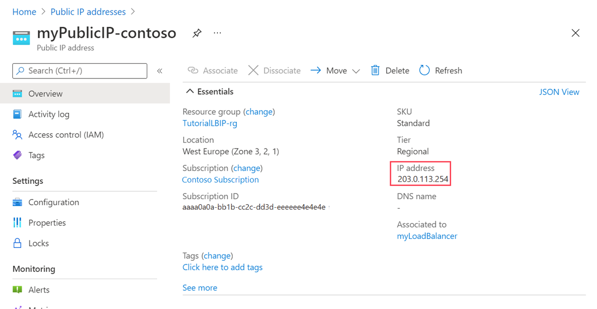
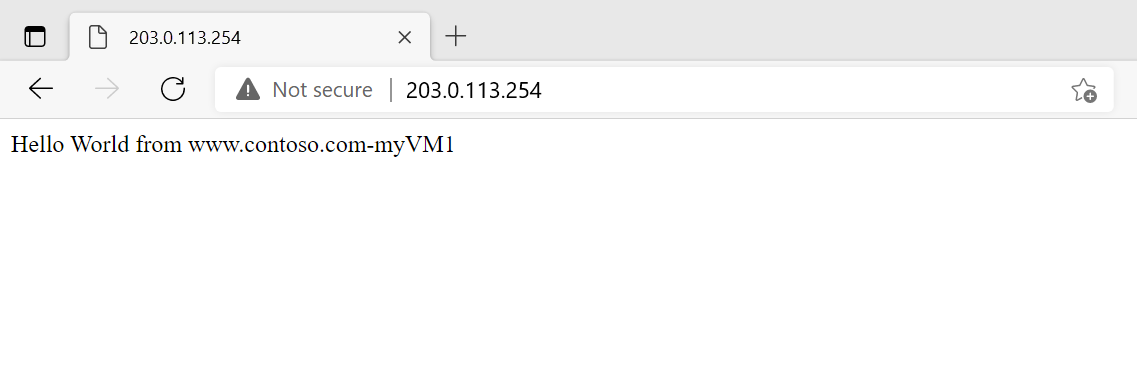
Open a web browser and paste the public IP address into the address bar.
Return to Public IP addresses. Select myPublicIP-fabrikam.
Copy the IP address in the overview page of myPublicIP-fabrikam.
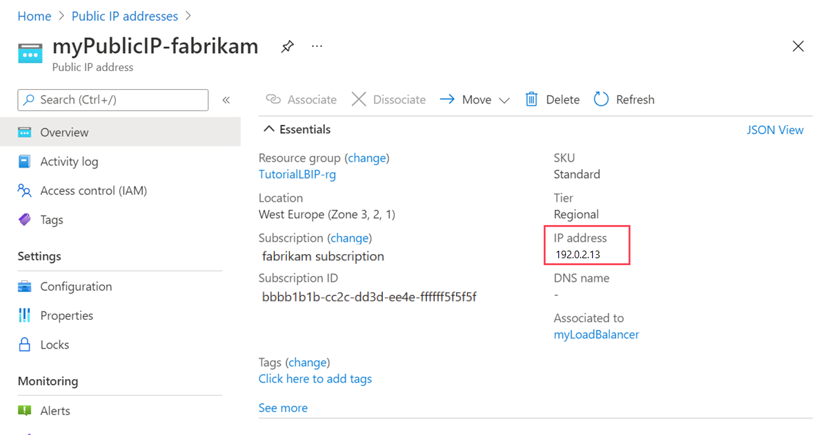
Open a web browser and paste the public IP address into the address bar.
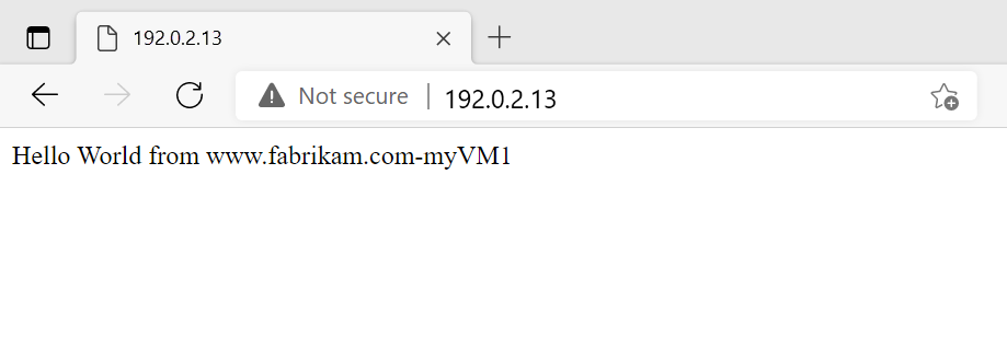
To test the load balancer, refresh the browser or shut down one of the virtual machines.
Clean up resources
If you're not going to continue to use this application, delete the virtual machines and load balancer with the following steps:
In the search box at the top of the portal, enter Resource group. Select Resource groups in the search results.
Select load-balancer-rg in Resource groups.
Select Delete resource group.
Enter load-balancer-rg in TYPE THE RESOURCE GROUP NAME:. Select Delete.
Load balance on multiple IP configurations
To achieve the scenario outlined in this article complete the following steps:
Install and Configure the Azure CLI by following the steps in the linked article and log into your Azure account.
Create a resource group called contosofabrikam as follows:
az group create contosofabrikam westcentralusCreate an availability set to for the two VMs. For this scenario, use the following command:
az vm availability-set create --resource-group contosofabrikam --location westcentralus --name myAvailabilitySetCreate a virtual network called myVNet and a subnet called mySubnet:
az network vnet create --resource-group contosofabrikam --name myVnet --address-prefixes 10.0.0.0/16 --location westcentralus --subnet-name MySubnet --subnet-prefix 10.0.0.0/24Create the load balancer called mylb:
az network lb create --resource-group contosofabrikam --location westcentralus --name mylbCreate two dynamic public IP addresses for the frontend IP configurations of your load balancer:
az network public-ip create --resource-group contosofabrikam --location westcentralus --name PublicIp1 --domain-name-label contoso --allocation-method Dynamic

az network public-ip create --resource-group contosofabrikam --location westcentralus --name PublicIp2 --domain-name-label fabrikam --allocation-method Dynamic
Create the two frontend IP configurations, contosofe and fabrikamfe respectively:
az network lb frontend-ip create --resource-group contosofabrikam --lb-name mylb --public-ip-name PublicIp1 --name contosofe
az network lb frontend-ip create --resource-group contosofabrikam --lb-name mylb --public-ip-name PublicIp2 --name fabrikamfe
Create your backend address pools - contosopool and fabrikampool, a probe - HTTP, and your load balancing rules - HTTPruleContoso and HTTPruleFabrikam:
az network lb address-pool create --resource-group contosofabrikam --lb-name mylb --name contosopool
azure network lb address-pool create --resource-group contosofabrikam --lb-name mylb --name fabrikampool

az network lb probe create --resource-group contosofabrikam --lb-name mylb --name HTTP --protocol "http" --interval 15 --count 2 --path index.html

az network lb rule create --resource-group contosofabrikam --lb-name mylb --name HTTPruleContoso --protocol tcp --probe-name http--frontend-port 5000 --backend-port 5000 --frontend-ip-name contosofe --backend-address-pool-name contosopool
az network lb rule create --resource-group contosofabrikam --lb-name mylb --name HTTPruleFabrikam --protocol tcp --probe-name http --frontend-port 5000 --backend-port 5000 --frontend-ip-name fabrikamfe --backend-address-pool-name fabrikampool
Check the output to verify your load balancer was created correctly by running the following command:
az network lb show --resource-group contosofabrikam --name mylbCreate a public IP, myPublicIp, and storage account, mystorageaccont1 for your first virtual machine VM1 as follows:
az network public-ip create --resource-group contosofabrikam --location westcentralus --name myPublicIP --domain-name-label mypublicdns345 --allocation-method Dynamic

az storage account create --location westcentralus --resource-group contosofabrikam --kind Storage --sku-name GRS mystorageaccount1
Create the network interfaces for VM1 and add a second IP configuration, VM1-ipconfig2, and create the VM as follows:
az network nic create --resource-group contosofabrikam --location westcentralus --subnet-vnet-name myVnet --subnet-name mySubnet --name VM1Nic1 --ip-config-name NIC1-ipconfig1
az network nic create --resource-group contosofabrikam --location westcentralus --subnet-vnet-name myVnet --subnet-name mySubnet --name VM1Nic2 --ip-config-name VM1-ipconfig1 --public-ip-name myPublicIP --lb-address-pool-ids "/subscriptions/<your subscription ID>/resourceGroups/contosofabrikam/providers/Microsoft.Network/loadBalancers/mylb/backendAddressPools/contosopool"
az network nic ip-config create --resource-group contosofabrikam --nic-name VM1Nic2 --name VM1-ipconfig2 --lb-address-pool-ids "/subscriptions/<your subscription ID>/resourceGroups/contosofabrikam/providers/Microsoft.Network/loadBalancers/mylb/backendAddressPools/fabrikampool"
az vm create --resource-group contosofabrikam --name VM1 --location westcentralus --os-type linux --nic-names VM1Nic1,VM1Nic2  --vnet-name VNet1 --vnet-subnet-name Subnet1 --availability-set myAvailabilitySet --vm-size Standard_DS3_v2 --storage-account-name mystorageaccount1 --image-urn canonical:UbuntuServer:16.04.0-LTS:latest --admin-username <your username>  --admin-password <your password>
Repeat steps 10-11 for your second VM:
az network public-ip create --resource-group contosofabrikam --location westcentralus --name myPublicIP2 --domain-name-label mypublicdns785 --allocation-method Dynamic
az storage account create --location westcentralus --resource-group contosofabrikam --kind Storage --sku-name GRS mystorageaccount2
az network nic create --resource-group contosofabrikam --location westcentralus --subnet-vnet-name myVnet --subnet-name mySubnet --name VM2Nic1
az network nic create --resource-group contosofabrikam --location westcentralus --subnet-vnet-name myVnet --subnet-name mySubnet --name VM2Nic2 --ip-config-name VM2-ipconfig1 --public-ip-name myPublicIP2 --lb-address-pool-ids "/subscriptions/<your subscription ID>/resourceGroups/contosofabrikam/providers/Microsoft.Network/loadBalancers/mylb/backendAddressPools/contosopool"
az network nic ip-config create --resource-group contosofabrikam --nic-name VM2Nic2 --name VM2-ipconfig2 --lb-address-pool-ids "/subscriptions/<your subscription ID>/resourceGroups/contosofabrikam/providers/Microsoft.Network/loadBalancers/mylb/backendAddressPools/fabrikampool"
az vm create --resource-group contosofabrikam --name VM2 --location westcentralus --os-type linux --nic-names VM2Nic1,VM2Nic2 --vnet-name VNet1 --vnet-subnet-name Subnet1 --availability-set myAvailabilitySet --vm-size Standard_DS3_v2 --storage-account-name mystorageaccount2 --image-urn canonical:UbuntuServer:16.04.0-LTS:latest --admin-username <your username>  --admin-password <your password>
Finally, you must configure DNS resource records to point to the respective frontend IP address of the Load Balancer. You can host your domains in Azure DNS. For more information about using Azure DNS with Load Balancer, see Using Azure DNS with other Azure services
Load balance on multiple IP configurations
Note
We recommend that you use the Azure Az PowerShell module to interact with Azure. To get started, see Install Azure PowerShell. To learn how to migrate to the Az PowerShell module, see Migrate Azure PowerShell from AzureRM to Az.
Use the following steps to create a load balancer that can balance traffic across multiple IP configurations on a single virtual machine (VM) with Azure PowerShell. This example uses two VMs, but you can use this same process for any number of VMs.
Install Azure PowerShell. See How to install and configure Azure PowerShell for information about installing the latest version of Azure PowerShell, selecting your subscription, and signing in to your account.
Create a resource group using the following settings:
$location = "westcentralus".
$myResourceGroup = "contosofabrikam"
For more information, see Step 2 of Create a Resource Group.
Create an Availability Set to contain your VMs. For this scenario, use the following command:
New-AzAvailabilitySet -ResourceGroupName "contosofabrikam" -Name "myAvailset" -Location "West Central US"Follow instructions steps 3 through 5 in Create a Windows VM article to prepare the creation of a VM with a single NIC. Execute step 6.1, and use the following instead of step 6.2:
$availset = Get-AzAvailabilitySet -ResourceGroupName "contosofabrikam" -Name "myAvailset"
New-AzVMConfig -VMName "VM1" -VMSize "Standard_DS1_v2" -AvailabilitySetId $availset.Id
Then complete Create a Windows VM steps 6.3 through 6.8.
Add a second IP configuration to each of the VMs. Follow the instructions in Assign multiple IP addresses to virtual machines article. Use the following configuration settings:
$NicName = "VM1-NIC2"
$RgName = "contosofabrikam"
$NicLocation = "West Central US"
$IPConfigName4 = "VM1-ipconfig2"
$Subnet1 = Get-AzVirtualNetworkSubnetConfig -Name "mySubnet" -VirtualNetwork $myVnet
You don't need to associate the secondary IP configurations with public IPs in this tutorial. Edit the command to remove the public IP association part.
Complete steps 4 through 6 again for VM2. Be sure to replace the VM name to
VM2in code examples. You don't need to create a virtual network for the second VM. You can create a new subnet based on your use case.Create two public IP addresses and store them in the appropriate variables as shown:
$publicIP1 = New-AzPublicIpAddress -Name PublicIp1 -ResourceGroupName contosofabrikam -Location 'West Central US' -AllocationMethod Dynamic -DomainNameLabel contoso
$publicIP2 = New-AzPublicIpAddress -Name PublicIp2 -ResourceGroupName contosofabrikam -Location 'West Central US' -AllocationMethod Dynamic -DomainNameLabel fabrikam

$publicIP1 = Get-AzPublicIpAddress -Name PublicIp1 -ResourceGroupName contosofabrikam
$publicIP2 = Get-AzPublicIpAddress -Name PublicIp2 -ResourceGroupName contosofabrikam
Create two frontend IP configurations:
$frontendIP1 = New-AzLoadBalancerFrontendIpConfig -Name contosofe -PublicIpAddress $publicIP1
$frontendIP2 = New-AzLoadBalancerFrontendIpConfig -Name fabrikamfe -PublicIpAddress $publicIP2
Create your backend address pools, a probe, and your load balancing rules:
$beaddresspool1 = New-AzLoadBalancerBackendAddressPoolConfig -Name contosopool
$beaddresspool2 = New-AzLoadBalancerBackendAddressPoolConfig -Name fabrikampool

$healthProbe = New-AzLoadBalancerProbeConfig -Name HTTP -RequestPath 'index.html' -Protocol http -Port 80 -IntervalInSeconds 15 -ProbeCount 2

$lbrule1 = New-AzLoadBalancerRuleConfig -Name HTTPc -FrontendIpConfiguration $frontendIP1 -BackendAddressPool $beaddresspool1 -Probe $healthprobe -Protocol Tcp -FrontendPort 80 -BackendPort 80
$lbrule2 = New-AzLoadBalancerRuleConfig -Name HTTPf -FrontendIpConfiguration $frontendIP2 -BackendAddressPool $beaddresspool2 -Probe $healthprobe -Protocol Tcp -FrontendPort 80 -BackendPort 80
Once you have these resources created, create your load balancer:
$mylb = New-AzLoadBalancer -ResourceGroupName contosofabrikam -Name mylb -Location 'West Central US' -FrontendIpConfiguration $frontendIP1 -LoadBalancingRule $lbrule -BackendAddressPool $beAddressPool -Probe $healthProbeAdd the second backend address pool and frontend IP configuration to your newly created load balancer:
$mylb = Get-AzLoadBalancer -Name "mylb" -ResourceGroupName $myResourceGroup | Add-AzLoadBalancerBackendAddressPoolConfig -Name fabrikampool | Set-AzLoadBalancer

$mylb | Add-AzLoadBalancerFrontendIpConfig -Name fabrikamfe -PublicIpAddress $publicIP2 | Set-AzLoadBalancer

Add-AzLoadBalancerRuleConfig -Name HTTP -LoadBalancer $mylb -FrontendIpConfiguration $frontendIP2 -BackendAddressPool $beaddresspool2 -Probe $healthProbe -Protocol Tcp -FrontendPort 80 -BackendPort 80 | Set-AzLoadBalancer
The following commands get the NICs and then add both IP configurations of each secondary NIC to the backend address pool of the load balancer:
$nic1 = Get-AzNetworkInterface -Name "VM1-NIC2" -ResourceGroupName "MyResourcegroup";
$nic2 = Get-AzNetworkInterface -Name "VM2-NIC2" -ResourceGroupName "MyResourcegroup";

$nic1.IpConfigurations[0].LoadBalancerBackendAddressPools.Add($mylb.BackendAddressPools[0]);
$nic1.IpConfigurations[1].LoadBalancerBackendAddressPools.Add($mylb.BackendAddressPools[1]);
$nic2.IpConfigurations[0].LoadBalancerBackendAddressPools.Add($mylb.BackendAddressPools[0]);
$nic2.IpConfigurations[1].LoadBalancerBackendAddressPools.Add($mylb.BackendAddressPools[1]);

$mylb = $mylb | Set-AzLoadBalancer

$nic1 | Set-AzNetworkInterface
$nic2 | Set-AzNetworkInterface
Finally, you must configure DNS resource records to point to the respective frontend IP address of the Load Balancer. You can host your domains in Azure DNS. For more information about using Azure DNS with Load Balancer, see Using Azure DNS with other Azure services.
Next steps
Advance to the next article to learn how to create a cross-region load balancer: