Note
Access to this page requires authorization. You can try signing in or changing directories.
Access to this page requires authorization. You can try changing directories.
This article describes the data plane analysis of the test setup. You can also review the test setup configuration and the control plane analysis of the test setup.
Data plane analysis examines the path taken by packets that traverse from one local network (LAN or virtual network) to another within a topology. The data path between two local networks isn't necessarily symmetrical. Therefore, in this article, we analyze a forwarding path from a local network to another network that's separate from the reverse path.
Data path from the hub virtual network
Path to the spoke virtual network
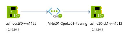
Virtual network peering emulates network bridge functionality between the two virtual networks that are peered. Traceroute output from a hub virtual network to a VM in the spoke virtual network is shown here:
C:\Users\rb>tracert 10.11.30.4

Tracing route to 10.11.30.4 over a maximum of 30 hops

  1     2 ms     1 ms     1 ms  10.11.30.4

Trace complete.
The following figure shows the graphical connection view of the hub virtual network and the spoke virtual network from the perspective of Azure Network Watcher:
Path to the branch virtual network
Traceroute output from a hub virtual network to a VM in the branch virtual network is shown here:
C:\Users\rb>tracert 10.11.30.68

Tracing route to 10.11.30.68 over a maximum of 30 hops

  1     1 ms     1 ms     1 ms  10.10.30.142
  2     *        *        *     Request timed out.
  3     2 ms     2 ms     2 ms  10.11.30.68

Trace complete.
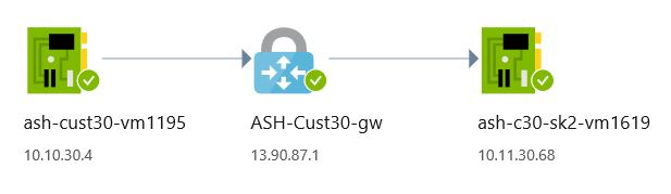
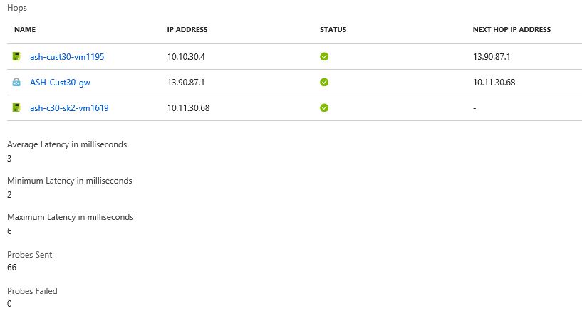
In this traceroute, the first hop is the VPN gateway in Azure VPN Gateway of the hub virtual network. The second hop is the VPN gateway of the branch virtual network. The IP address of the VPN gateway of the branch virtual network isn't advertised in the hub virtual network. The third hop is the VM on the branch virtual network.
The following figure shows the graphical connection view of the hub virtual network and the branch virtual network from the perspective of Network Watcher:
For the same connection, the following figure shows the grid view in Network Watcher:
Path to on-premises Location 1
Traceroute output from a hub virtual network to a VM in on-premises Location 1 is shown here:
C:\Users\rb>tracert 10.2.30.10

Tracing route to 10.2.30.10 over a maximum of 30 hops

  1     2 ms     2 ms     2 ms  10.10.30.132
  2     *        *        *     Request timed out.
  3     *        *        *     Request timed out.
  4     2 ms     2 ms     2 ms  10.2.30.10

Trace complete.
In this traceroute, the first hop is the Azure ExpressRoute gateway tunnel endpoint to a Microsoft Enterprise edge router (MSEE). The second and third hops are the customer edge (CE) router and the on-premises Location 1 LAN IPs. These IP addresses aren't advertised in the hub virtual network. The fourth hop is the VM in the on-premises Location 1.
Path to on-premises Location 2
Traceroute output from a hub virtual network to a VM in on-premises Location 2 is shown here:
C:\Users\rb>tracert 10.1.31.10

Tracing route to 10.1.31.10 over a maximum of 30 hops

  1    76 ms    75 ms    75 ms  10.10.30.134
  2     *        *        *     Request timed out.
  3     *        *        *     Request timed out.
  4    75 ms    75 ms    75 ms  10.1.31.10

Trace complete.
In this traceroute, the first hop is the ExpressRoute gateway tunnel endpoint to an MSEE. The second and third hops are the CE router and the on-premises Location 2 LAN IPs. These IP addresses aren't advertised in the hub virtual network. The fourth hop is the VM on the on-premises Location 2.
Path to the remote virtual network
Traceroute output from a hub virtual network to a VM in the remote virtual network is shown here:
C:\Users\rb>tracert 10.17.30.4

Tracing route to 10.17.30.4 over a maximum of 30 hops

  1     2 ms     2 ms     2 ms  10.10.30.132
  2     *        *        *     Request timed out.
  3    69 ms    68 ms    69 ms  10.17.30.4

Trace complete.
In this traceroute, the first hop is the ExpressRoute gateway tunnel endpoint to an MSEE. The second hop is the remote virtual network's gateway IP. The second hop IP range isn't advertised in the hub virtual network. The third hop is the VM on the remote virtual network.
Data path from the spoke virtual network
The spoke virtual network shares the network view of the hub virtual network. Through virtual network peering, the spoke virtual network uses the remote gateway connectivity of the hub virtual network as if it's directly connected to the spoke virtual network.
Path to the hub virtual network
Traceroute output from the spoke virtual network to a VM in the hub virtual network is shown here:
C:\Users\rb>tracert 10.10.30.4

Tracing route to 10.10.30.4 over a maximum of 30 hops

  1    <1 ms    <1 ms    <1 ms  10.10.30.4

Trace complete.
Path to the branch virtual network
Traceroute output from the spoke virtual network to a VM in the branch virtual network is shown here:
C:\Users\rb>tracert 10.11.30.68

Tracing route to 10.11.30.68 over a maximum of 30 hops

  1     1 ms    <1 ms    <1 ms  10.10.30.142
  2     *        *        *     Request timed out.
  3     3 ms     2 ms     2 ms  10.11.30.68

Trace complete.
In this traceroute, the first hop is the VPN gateway of the hub virtual network. The second hop is the VPN gateway of the branch virtual network. The IP address of the VPN gateway of the branch virtual network isn't advertised within the hub/spoke virtual network. The third hop is the VM on the branch virtual network.
Path to on-premises Location 1
Traceroute output from the spoke virtual network to a VM in on-premises Location 1 is shown here:
C:\Users\rb>tracert 10.2.30.10

Tracing route to 10.2.30.10 over a maximum of 30 hops

  1    24 ms     2 ms     3 ms  10.10.30.132
  2     *        *        *     Request timed out.
  3     *        *        *     Request timed out.
  4     3 ms     2 ms     2 ms  10.2.30.10

Trace complete.
In this traceroute, the first hop is the hub virtual network's ExpressRoute gateway tunnel endpoint to an MSEE. The second and third hops are the CE router and the on-premises Location 1 LAN IPs. These IP addresses aren't advertised in the hub/spoke virtual network. The fourth hop is the VM in the on-premises Location 1.
Path to on-premises Location 2
Traceroute output from the spoke virtual network to a VM in on-premises Location 2 is shown here:
C:\Users\rb>tracert 10.1.31.10

Tracing route to 10.1.31.10 over a maximum of 30 hops

  1    76 ms    75 ms    76 ms  10.10.30.134
  2     *        *        *     Request timed out.
  3     *        *        *     Request timed out.
  4    75 ms    75 ms    75 ms  10.1.31.10

Trace complete.
In this traceroute, the first hop is the hub virtual network's ExpressRoute gateway tunnel endpoint to an MSEE. The second and third hops are the CE router and the on-premises Location 2 LAN IPs. These IP addresses aren't advertised in the hub/spoke virtual networks. The fourth hop is the VM in the on-premises Location 2.
Path to the remote virtual network
Traceroute output from the spoke virtual network to a VM in the remote virtual network is shown here:
C:\Users\rb>tracert 10.17.30.4

Tracing route to 10.17.30.4 over a maximum of 30 hops

  1     2 ms     1 ms     1 ms  10.10.30.133
  2     *        *        *     Request timed out.
  3    71 ms    70 ms    70 ms  10.17.30.4

Trace complete.
In this traceroute, the first hop is the hub virtual network's ExpressRoute gateway tunnel endpoint to an MSEE. The second hop is the remote virtual network's gateway IP. The second hop IP range isn't advertised in the hub/spoke virtual network. The third hop is the VM on the remote virtual network.
Data path from the branch virtual network
Path to the hub virtual network
Traceroute output from the branch virtual network to a VM in the hub virtual network is shown here:
C:\Windows\system32>tracert 10.10.30.4

Tracing route to 10.10.30.4 over a maximum of 30 hops

  1    <1 ms    <1 ms    <1 ms  10.11.30.100
  2     *        *        *     Request timed out.
  3     4 ms     3 ms     3 ms  10.10.30.4

Trace complete.
In this traceroute, the first hop is the VPN gateway of the branch virtual network. The second hop is the VPN gateway of the hub virtual network. The IP address of the VPN gateway of the hub virtual network isn't advertised in the remote virtual network. The third hop is the VM on the hub virtual network.
Path to the spoke virtual network
Traceroute output from the branch virtual network to a VM in the spoke virtual network is shown here:
C:\Users\rb>tracert 10.11.30.4

Tracing route to 10.11.30.4 over a maximum of 30 hops

  1     1 ms    <1 ms     1 ms  10.11.30.100
  2     *        *        *     Request timed out.
  3     4 ms     3 ms     2 ms  10.11.30.4

Trace complete.
In this traceroute, the first hop is the VPN gateway of the branch virtual network. The second hop is the VPN gateway of the hub virtual network. The IP address of the VPN gateway of the hub virtual network isn't advertised in the remote virtual network. The third hop is the VM on the spoke virtual network.
Path to on-premises Location 1
Traceroute output from the branch virtual network to a VM in on-premises Location 1 is shown here:
C:\Users\rb>tracert 10.2.30.10

Tracing route to 10.2.30.10 over a maximum of 30 hops

  1     1 ms    <1 ms    <1 ms  10.11.30.100
  2     *        *        *     Request timed out.
  3     3 ms     2 ms     2 ms  10.2.30.125
  4     *        *        *     Request timed out.
  5     3 ms     3 ms     3 ms  10.2.30.10

Trace complete.
In this traceroute, the first hop is the VPN gateway of the branch virtual network. The second hop is the VPN gateway of the hub virtual network. The IP address of the VPN gateway of the hub virtual network isn't advertised in the remote virtual network. The third hop is the VPN tunnel termination point on the primary CE router. The fourth hop is an internal IP address of on-premises Location 1. This LAN IP address isn't advertised outside the CE router. The fifth hop is the destination VM in the on-premises Location 1.
Path to on-premises Location 2 and the remote virtual network
As we discussed in the control plane analysis, the branch virtual network has no visibility either to on-premises Location 2 or to the remote virtual network per the network configuration. The following ping results confirm:
C:\Users\rb>ping 10.1.31.10

Pinging 10.1.31.10 with 32 bytes of data:

Request timed out.
...
Request timed out.

Ping statistics for 10.1.31.10:
    Packets: Sent = 4, Received = 0, Lost = 4 (100% loss),

C:\Users\rb>ping 10.17.30.4

Pinging 10.17.30.4 with 32 bytes of data:

Request timed out.
...
Request timed out.

Ping statistics for 10.17.30.4:
    Packets: Sent = 4, Received = 0, Lost = 4 (100% loss),
Data path from on-premises Location 1
Path to the hub virtual network
Traceroute output from on-premises Location 1 to a VM in the hub virtual network is shown here:
C:\Users\rb>tracert 10.10.30.4

Tracing route to 10.10.30.4 over a maximum of 30 hops

  1    <1 ms    <1 ms    <1 ms  10.2.30.3
  2    <1 ms    <1 ms    <1 ms  192.168.30.0
  3    <1 ms    <1 ms    <1 ms  192.168.30.18
  4     *        *        *     Request timed out.
  5     2 ms     2 ms     2 ms  10.10.30.4

Trace complete.
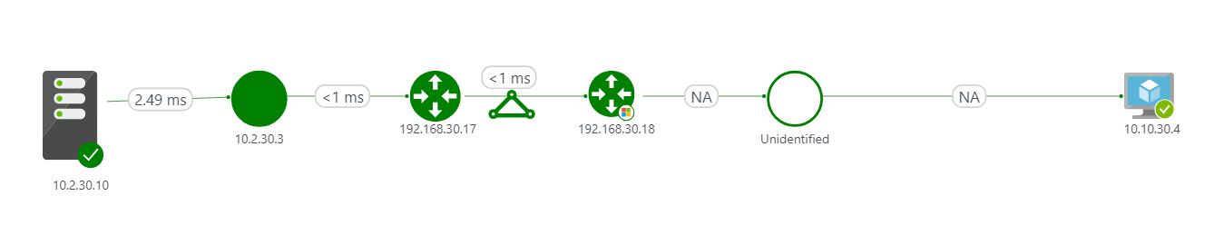
In this traceroute, the first two hops are part of the on-premises network. The third hop is the primary MSEE interface that faces the CE router. The fourth hop is the ExpressRoute gateway of the hub virtual network. The IP range of the ExpressRoute gateway of the hub virtual network isn't advertised to the on-premises network. The fifth hop is the destination VM.
Network Watcher provides only an Azure-centric view. For an on-premises perspective, use Connection Monitor in Azure Network Watcher. Connection Monitor provides agents that you can install on servers in networks outside Azure for data path analysis.
Note
The topology views in this section were captured by using Azure Network Performance Monitor and are included for historical reference. Network Performance Monitor no longer accepts new tests in an existing workspace or new workspaces. For current analysis, use Connection Monitor. For more information, see Migrate to Connection Monitor from Network Performance Monitor.
The following figure shows the topology view of the on-premises Location 1 VM connectivity to the VM on the hub virtual network via ExpressRoute:
As discussed earlier, the test setup uses a site-to-site VPN as backup connectivity for ExpressRoute between the on-premises Location 1 and the hub virtual network. To test the backup data path, let's induce an ExpressRoute link failure between the on-premises Location 1 primary CE router and the corresponding MSEE. To induce an ExpressRoute link failure, shut down the CE interface that faces the MSEE:
C:\Users\rb>tracert 10.10.30.4

Tracing route to 10.10.30.4 over a maximum of 30 hops

  1    <1 ms    <1 ms    <1 ms  10.2.30.3
  2    <1 ms    <1 ms    <1 ms  192.168.30.0
  3     3 ms     2 ms     3 ms  10.10.30.4

Trace complete.
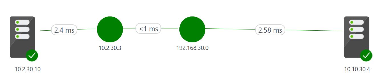
The topology view of the on-premises Location 1 VM connectivity is shown in the following figure. This connectivity is established to the VM on the hub virtual network. The connectivity is achieved via site-to-site VPN connectivity when ExpressRoute connectivity is down:
Path to the spoke virtual network
Traceroute output from on-premises Location 1 to a VM in the spoke virtual network is shown here:
Let's bring back the ExpressRoute primary connectivity to do the data path analysis toward the spoke virtual network:
C:\Users\rb>tracert 10.11.30.4

Tracing route to 10.11.30.4 over a maximum of 30 hops

  1    <1 ms    <1 ms    <1 ms  10.2.30.3
  2    <1 ms    <1 ms    <1 ms  192.168.30.0
  3    <1 ms    <1 ms    <1 ms  192.168.30.18
  4     *        *        *     Request timed out.
  5     3 ms     2 ms     2 ms  10.11.30.4

Trace complete.
Bring up the primary ExpressRoute 1 connectivity for the remainder of the data path analysis.
Path to the branch virtual network
Traceroute output from on-premises Location 1 to a VM in the branch virtual network is shown here:
C:\Users\rb>tracert 10.11.30.68

Tracing route to 10.11.30.68 over a maximum of 30 hops

  1    <1 ms    <1 ms    <1 ms  10.2.30.3
  2    <1 ms    <1 ms    <1 ms  192.168.30.0
  3     3 ms     2 ms     2 ms  10.11.30.68

Trace complete.
Path to on-premises Location 2
As we discuss in the control plane analysis, the on-premises Location 1 has no visibility to on-premises Location 2 per the network configuration. The following ping results confirm:
C:\Users\rb>ping 10.1.31.10

Pinging 10.1.31.10 with 32 bytes of data:

Request timed out.
...
Request timed out.

Ping statistics for 10.1.31.10:
    Packets: Sent = 4, Received = 0, Lost = 4 (100% loss),
Path to the remote virtual network
Traceroute output from on-premises Location 1 to a VM in the remote virtual network is shown here:
C:\Users\rb>tracert 10.17.30.4

Tracing route to 10.17.30.4 over a maximum of 30 hops

  1    <1 ms    <1 ms    <1 ms  10.2.30.3
  2     2 ms     5 ms     7 ms  192.168.30.0
  3    <1 ms    <1 ms    <1 ms  192.168.30.18
  4     *        *        *     Request timed out.
  5    69 ms    70 ms    69 ms  10.17.30.4

Trace complete.
Data path from on-premises Location 2
Path to the hub virtual network
Traceroute output from on-premises Location 2 to a VM in the hub virtual network is shown here:
C:\Windows\system32>tracert 10.10.30.4

Tracing route to 10.10.30.4 over a maximum of 30 hops

  1    <1 ms    <1 ms    <1 ms  10.1.31.3
  2    <1 ms    <1 ms    <1 ms  192.168.31.4
  3    <1 ms    <1 ms    <1 ms  192.168.31.22
  4     *        *        *     Request timed out.
  5    75 ms    74 ms    74 ms  10.10.30.4

Trace complete.
Path to the spoke virtual network
Traceroute output from on-premises Location 2 to a VM in the spoke virtual network is shown here:
C:\Windows\system32>tracert 10.11.30.4

Tracing route to 10.11.30.4 over a maximum of 30 hops
  1    <1 ms    <1 ms     1 ms  10.1.31.3
  2    <1 ms    <1 ms    <1 ms  192.168.31.0
  3    <1 ms    <1 ms    <1 ms  192.168.31.18
  4     *        *        *     Request timed out.
  5    75 ms    74 ms    74 ms  10.11.30.4

Trace complete.
Path to the branch virtual network, on-premises Location 1, and the remote virtual network
As discussed in the control plane analysis, on-premises Location 2 has no visibility to the branch virtual network, to on-premises Location 1, or to the remote virtual network according to the network configuration.
Data path from the remote virtual network
Path to the hub virtual network
Traceroute output from the remote virtual network to a VM in the hub virtual network is shown here:
C:\Users\rb>tracert 10.10.30.4

Tracing route to 10.10.30.4 over a maximum of 30 hops

  1    65 ms    65 ms    65 ms  10.17.30.36
  2     *        *        *     Request timed out.
  3    69 ms    68 ms    68 ms  10.10.30.4

Trace complete.
Path to the spoke virtual network
Traceroute output from the remote virtual network to a VM in the spoke virtual network is shown here:
C:\Users\rb>tracert 10.11.30.4

Tracing route to 10.11.30.4 over a maximum of 30 hops

  1    67 ms    67 ms    67 ms  10.17.30.36
  2     *        *        *     Request timed out.
  3    71 ms    69 ms    69 ms  10.11.30.4

Trace complete.
Path to the branch virtual network and on-premises Location 2
As we discuss in the control plane analysis, the remote virtual network has no visibility to the branch virtual network or to on-premises Location 2 per the network configuration.
Path to on-premises Location 1
Traceroute output from the remote virtual network to a VM in on-premises Location 1 is shown here:
C:\Users\rb>tracert 10.2.30.10

Tracing route to 10.2.30.10 over a maximum of 30 hops

  1    67 ms    67 ms    67 ms  10.17.30.36
  2     *        *        *     Request timed out.
  3     *        *        *     Request timed out.
  4    69 ms    69 ms    69 ms  10.2.30.10

Trace complete.
Next steps
Review the test setup for the topology, the Azure networking components it uses, and the shared guidance about running ExpressRoute and a site-to-site VPN in tandem and extending back-end connectivity to spoke virtual networks and branch locations.
Learn about the control plane analysis of the test setup.
See the ExpressRoute FAQ to:
Learn how many ExpressRoute circuits you can connect to an ExpressRoute gateway.
Learn how many ExpressRoute gateways you can connect to an ExpressRoute circuit.
Learn about other scale limits of ExpressRoute.