Note
Access to this page requires authorization. You can try signing in or changing directories.
Access to this page requires authorization. You can try changing directories.
When working with Virtual WAN virtual hub routing, there are quite a few available scenarios. In this NVA scenario, the goal is to route traffic through an NVA (Network Virtual Appliance) for branch to virtual network and virtual network to branch. For information about virtual hub routing, see About virtual hub routing.
Note
If you already have a setup with routes that are prior to the new capabilities How to configure virtual hub routing becoming available, use the steps in these versions of the articles:
Design
In this scenario we'll use the following naming convention:
- "NVA VNets" for virtual networks where users have deployed an NVA and have connected other virtual networks as spokes (VNet 2 and VNet 4 in the Figure 2 further down in the article).
- "NVA Spokes" for virtual networks connected to an NVA VNet (VNet 5, VNet 6, VNet 7, and VNet 8 in the Figure 2 further down in the article).
- "Non-NVA VNets" for virtual networks connected to Virtual WAN that don't have an NVA or other VNets peered with them (VNet 1 and VNet 3 in the Figure 2 further down in the article).
- "Hubs" for Microsoft-managed Virtual WAN Hubs, where NVA VNets are connected to. NVA spoke VNets don't need to be connected to Virtual WAN hubs, only to NVA VNets.
The following connectivity matrix summarizes the flows supported in this scenario:
Connectivity matrix
| From | To: | NVA Spokes | NVA VNets | Non-NVA VNets | Branches |
|---|---|---|---|---|---|
| NVA Spokes | → | Over NVA VNet | Peering | Over NVA VNet | Over NVA VNet |
| NVA VNets | → | Peering | Direct | Direct | Direct |
| Non-NVA VNets | → | Over NVA VNet | Direct | Direct | Direct |
| Branches | → | Over NVA VNet | Direct | Direct | Direct |
Each of the cells in the connectivity matrix describes how a VNet or branch (the "From" side of the flow, the row headers in the table) communicates with a destination VNet or branch (the "To" side of the flow, the column headers in italics in the table). "Direct" means that connectivity is provided natively by Virtual WAN, "Peering" means that connectivity is provided by a User-Defined Route in the VNet, "Over NVA VNet" means that the connectivity traverses the NVA deployed in the NVA VNet. Consider the following items:
- NVA Spokes aren't managed by Virtual WAN. As a result, the mechanisms with which they'll communicate to other VNets or branches are maintained by the user. Connectivity to the NVA VNet is provided by a VNet peering, and a Default route to 0.0.0.0/0 pointing to the NVA as next hop should cover connectivity to the Internet, to other spokes, and to branches
- NVA VNets knows about their own NVA spokes, but not about NVA spokes connected to other NVA VNets. For example, in the Figure 2 further down in this article, VNet 2 knows about VNet 5 and VNet 6, but not about other spokes such as VNet 7 and VNet 8. A static route is required to inject other spokes' prefixes into NVA VNets
- Similarly, branches and non-NVA VNets won't know about any NVA spoke, since NVA spokes aren't connected to Virtual WAN hubs. As a result, static routes are needed here as well.
Taking into account that the NVA spokes aren't managed by Virtual WAN, all other rows show the same connectivity pattern. As a result, a single route table (the Default one) is:
- Virtual networks (non-hub VNets and user-hub VNets):
- Associated route table: Default
- Propagating to route tables: Default
- Branches:
- Associated route table: Default
- Propagating to route tables: Default
However, in this scenario we need to think about which static routes to configure. Each static route has two components, one part in the Virtual WAN hub telling the Virtual WAN components which connection to use for each spoke, and another one in that specific connection pointing to the concrete IP address assigned to the NVA (or to a load balancer in front of multiple NVAs), as Figure 1 shows:
Figure 1
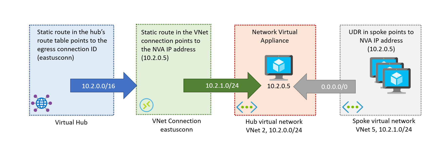
With that, the static routes that we need in the Default table to send traffic to the NVA spokes behind the NVA VNet are as follows:
| Description | Route table | Static route |
|---|---|---|
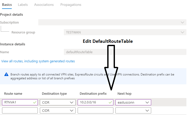
| VNet 2 | Default | 10.2.0.0/16 -> eastusconn |
| VNet 4 | Default | 10.4.0.0/16 -> weconn |
Now, these static routes will be advertised to your on-premises branches, and the Virtual WAN hub will know which VNet connection to forward traffic to. However, the VNet connection needs to know what to do when receiving this traffic: This is where the connection route tables are used. Here we'll use the shorter prefixes (/24 instead of the longer /16), to make sure that these routes have preference over routes that are imported from the NVA VNets (VNet 2 and VNet 4):
| Description | Connection | Static route |
|---|---|---|
| VNet 5 | eastusconn | 10.2.1.0/24 -> 10.2.0.5 |
| VNet 6 | eastusconn | 10.2.2.0/24 -> 10.2.0.5 |
| VNet 7 | weconn | 10.4.1.0/24 -> 10.4.0.5 |
| VNet 8 | weconn | 10.4.2.0/24 -> 10.4.0.5 |
Now NVA VNets, non-NVA VNets, and branches know how to reach all NVA spokes. For more information about virtual hub routing, see About virtual hub routing.
Architecture
In Figure 2, there are two hubs; Hub1 and Hub2.
Hub1 and Hub2 are directly connected to NVA VNets VNet 2 and VNet 4.
VNet 5 and VNet 6 are peered with VNet 2.
VNet 7 and VNet 8 are peered with VNet 4.
VNets 5,6,7,8 are indirect spokes, not directly connected to a virtual hub.
Figure 2

Considerations
For this scenario, you can use either a third party NVA, or Azure Firewall in VNet 2 and VNet 4.
This scenario doesn't support Secure Hubs with Routing Intent due to the routing policies limitations regarding static routes. However, you can use the BGP peering feature to use indirect spokes together with Secure Hubs with Routing Intent.
Scenario workflow
To set up routing via NVA, here are the steps to consider:
Identify the NVA spoke VNet connection. In Figure 2, they're VNet 2 Connection (eastusconn) and VNet 4 Connection (weconn).
Ensure there are UDRs set up:
- From VNet 5 and VNet 6 to VNet 2 NVA IP
- From VNet 7 and VNet 8 to VNet 4 NVA IP
You don't need to connect VNets 5,6,7,8 to the virtual hubs directly. Ensure that NSGs in VNets 5,6,7,8 allow traffic for branch (VPN/ER/P2S) or VNets connected to their remote VNets. For example, VNets 5,6 must ensure NSGs allow traffic for on-premises address prefixes and VNets 7,8 that are connected to the remote Hub 2.
Virtual WAN doesn't support a scenario where VNets 5,6 connect to virtual hub and communicate via VNet 2 NVA IP; therefore the need to connect VNets 5,6 to VNet2 and similarly VNet 7,8 to VNet 4.
Add an aggregated static route entry for VNets 2,5,6 to Hub 1’s Default route table.
Note
To simplify the routing and to reduce the changes in the Virtual WAN hub route tables, we recommend the new BGP peering with Virtual WAN hub. For more information, see the following articles:
Configure a static route for VNets 5,6 in VNet 2’s virtual network connection. To set up routing configuration for a virtual network connection, see virtual hub routing.
Add an aggregated static route entry for VNets 4,7,8 to Hub 1’s Default route table.
Repeat steps 2, 3 and 4 for Hub 2’s Default route table.
This results in the routing configuration changes, as shown in Figure 3.
Figure 3

Next steps
- For more information about Virtual WAN, see the FAQ.
- For more information about virtual hub routing, see About virtual hub routing.