Note
Access to this page requires authorization. You can try signing in or changing directories.
Access to this page requires authorization. You can try changing directories.
General-purpose I/O (GPIO) pins can be configured to receive electrical signals as input. At its most basic level, this is useful for scenarios that detect the opening/closing of a circuit. Such circuits might include push buttons, toggle switches, reed switches, pressure switches, and other devices that represent binary (on/off) values by completing a circuit.
In this tutorial, you'll use .NET and your Raspberry Pi's GPIO pins to detect the opening and closing of a circuit.
Prerequisites
- ARM-based (ARMv7 or greater) single-board computer (SBC)
- Jumper wires
- Breadboard (optional)
- Raspberry Pi GPIO breakout board (optional)
- .NET SDK 10 or later
Note
This tutorial is written assuming the target device is Raspberry Pi. However, this tutorial can be used for any Linux-based SBC that supports .NET, such as Orange Pi, ODROID, and more.
Ensure SSH is enabled on your device. For Raspberry Pi, refer to Setting up an SSH Server in the Raspberry Pi documentation.
Prepare the hardware
Use the hardware components to build the circuit as depicted in the following diagram:

The image above depicts a direct connection between a ground pin and pin 21.
Tip
The diagram depicts a breadboard and GPIO breakout for illustrative purposes, but feel free to just connect a ground pin and pin 21 with a jumper wire on the Raspberry Pi.
Refer to the following pinout diagram as needed:

Image courtesy Raspberry Pi Foundation.
Create the app
Complete the following steps in your preferred development environment:
Create a new .NET Console App using either the .NET CLI or Visual Studio. Name it InputTutorial.
dotnet new console -o InputTutorial
cd InputTutorial
Add the System.Device.Gpio package to the project. Use either .NET CLI from the project directory or Visual Studio.
dotnet package add System.Device.Gpio --version 4.0.1Replace the contents of Program.cs with the following code:
using System.Device.Gpio;
using System.Threading.Tasks;

const int Pin = 21;
const string Alert = "ALERT 🚨";
const string Ready = "READY ✅";

using var controller = new GpioController();
controller.OpenPin(Pin, PinMode.InputPullUp);

Console.WriteLine(
    $"Initial status ({DateTime.Now}): {(controller.Read(Pin) == PinValue.High ? Alert : Ready)}");

controller.RegisterCallbackForPinValueChangedEvent(
    Pin,
    PinEventTypes.Falling | PinEventTypes.Rising,
    OnPinEvent);

await Task.Delay(Timeout.Infinite);

static void OnPinEvent(object sender, PinValueChangedEventArgs args)
{
    Console.WriteLine(
        $"({DateTime.Now}) {(args.ChangeType is PinEventTypes.Rising ? Alert : Ready)}");
}
In the preceding code:
- A using declaration creates an instance of
GpioController. Theusingdeclaration ensures the object is disposed and hardware resources are released properly.GpioControlleris instantiated with no parameters, indicating that it should detect which hardware platform it's running on and use the logical pin numbering scheme.
- GPIO pin 21 is opened with
PinMode.InputPullUp.- This opens the pin with a PullUp resistor engaged. In this mode, when the pin is connected to ground, it will return
PinValue.Low. When the pin is disconnected from ground and the circuit is open, the pin returnsPinValue.High.
- This opens the pin with a PullUp resistor engaged. In this mode, when the pin is connected to ground, it will return
- The initial status is written to a console using a ternary expression. The pin's current state is read with
Read(). If it'sPinValue.High, it writes theAlertstring to the console. Otherwise, it writes theReadystring. RegisterCallbackForPinValueChangedEvent()registers a callback function for both thePinEventTypes.RisingandPinEventTypes.Fallingevents on the pin. These events correspond to pin states ofPinValue.HighandPinValue.Low, respectively.- The callback function points to a method called
OnPinEvent().OnPinEvent()uses another ternary expression that also writes the correspondingAlertorReadystrings. - The main thread sleeps indefinitely while waiting for pin events.
- A using declaration creates an instance of
Build the app. If using the .NET CLI, run
dotnet build. To build in Visual Studio, press Ctrl+Shift+B.Deploy the app to the SBC as a self-contained app. For instructions, see Deploy .NET apps to Raspberry Pi. Make sure to give the executable execute permission using
chmod +x.Run the app on the Raspberry Pi by switching to the deployment directory and running the executable.
./InputTutorialThe console displays text similar to the following:
Initial status (05/10/2022 15:59:25): READY ✅Disconnect pin 21 from ground. The console displays text similar to the following:
(05/10/2022 15:59:59) ALERT 🚨Reconnect pin 21 and ground. The console displays text similar to the following:
(05/10/2022 16:00:25) READY ✅Terminate the program by pressing Ctrl+C.
Congratulations! You've used GPIO to detect input using the System.Device.Gpio NuGet package! There are many uses for this type of input. This example can be used with any scenario where a switch connects or breaks a circuit. Here's an example using it with a magnetic reed switch, which is often used to detect open doors or windows.
Laser tripwire
Extending the previous example concept a bit further, let's take a look at how this could be applied to creating a laser tripwire. Building a laser tripwire requires the following additional components:
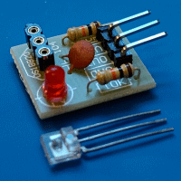
- KY-008 laser transmitter module
- Laser receiver sensor module (see note below)
- 2 10K Ω resistors
Note
Laser receiver sensor module is the generic name applied to a common module found at many internet retailers. The device may vary in name or manufacturer, but should resemble this image.
Connect laser tripwire hardware
Connect the components as detailed in the following diagram.

Pay close attention to the 10K Ω resistors. These implement a voltage divider. This is because the laser receiver module outputs 5V to indicate the beam is broken. Raspberry Pi only supports up to 3.3V for GPIO input. Since sending the full 5V to the pin could damage the Raspberry Pi, the current from the receiver module is passed through a voltage divider to halve the voltage to 2.5V.
Apply source code updates
You can almost use the same code as earlier, with one exception. In the other examples, we used PinMode.InputPullUp so that when the pin is disconnected from ground and the circuit is open, the pin returns PinValue.High.
However, in the case of the laser receiver module, we're not detecting an open circuit. Instead, we want the pin to act as a sink for current coming from the laser receiver module. In this case, we'll open the pin with PinMode.InputPullDown. This way, the pin returns PinValue.Low when it's getting no current, and PinValue.High when it receives current from the laser receiver module.
controller.OpenPin(pin, PinMode.InputPullDown);
Important
Make sure the code deployed on your Raspberry Pi includes this change before testing a laser tripwire. The program does work without it, but using the wrong input mode risks damage to your Raspberry Pi!
Get the source code
The source for this tutorial is available on GitHub.
Next steps
Collaborate with us on GitHub
The source for this content can be found on GitHub, where you can also create and review issues and pull requests. For more information, see our contributor guide.