Use SideFX Houdini to turn point clouds into optimized 3D objects for Dynamics 365 Guides and for mixed-reality components in apps created with Power Apps
This tutorial provides step-by-step instructions for the following tasks:
Convert a point cloud into a 3D object.
Optimize a 3D object by reducing the polygon count so that it matches performance targets for Dynamics 365 mixed-reality applications.
Export an optimized 3D object as a .glb file that can be used in Dynamics 365 Guides and mixed-reality components in apps created with Power Apps
Create a processing pipeline template, so that you can quickly optimize point clouds in the future.
This tutorial is for informational purposes only, to show how SideFX Houdini works with Microsoft Dynamics 365 Guides and Power Apps. Your use of third-party applications is subject to terms between you and the third party. Microsoft Corporation isn't affiliated with, isn't a partner of, and doesn't endorse or sponsor SideFX or any of its products. There are several other content-creation applications that you can use to prepare your 3D objects.
What is Houdini?
Houdini is a tool for creating 3D procedural content. It uses a nondestructive node-based tool system to design process pipelines and 3D content.
Set up your environment
To set up your environment, you must complete these tasks:
Install the SideFX Labs extension.
Set up AliceVision for photogrammetry.
Install the SideFX Labs extension
SideFX Labs is a testing ground for tools that can help you get up and running with Houdini more quickly. This collection of free tools includes tools that are useful for converting point clouds to optimized 3D objects. To use SideFX Labs, you must be using Houdini 18 or later.
SideFX provides a tutorial video that helps you install these tools.
Note
You must install Houdini before you can install SideFX Labs. Learn more about how to install Houdini.
Open Houdini.
To install SideFX Labs, select the plus sign
 at the top of the Houdini window, select Shelves, and then select the SideFX Labs check box.
On the toolbar that appears near the top of the window, select Update Toolset to open the installer.
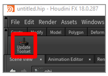
Select Update to install the tools.
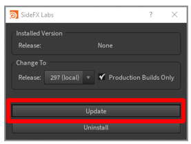
If the installation is successful, more tools appear on the toolbar. You can then continue with this tutorial.
Set up AliceVision for photogrammetry
AliceVision is a photogrammetric computer vision framework that was developed by Mikros Image. It provides 3D reconstruction and camera tracking algorithms. Learn more about AliceVision and the AliceVision plug-in.
For information about how to install and set up the AliceVision plug-in for Houdini, see the SideFX tutorial.
Import a point cloud into Houdini
Houdini can import point cloud files in the PLY file format. If your file is in a PTS file format, you can manually convert it to the PLY format.
Convert a .pts file to a .ply file
Open your .pts file in a file editor of your choice, and add the following header.
************************
ply
format ascii 1.0
element vertex 534993
property float x
property float y
property float z
property uchar intensity
property uchar red
property uchar green
property uchar blue
end_header
************************
In the header, next to element vertex, replace the value 534993 with the value that originally appeared at the top of your .pts file (but now immediately follows the header).

This value is the total number of points in your point cloud.
Remove the original value after the header. The following table shows a side-by-side comparison of the files before and after you make the preceding changes. The element vertex value is highlighted in red.
Top of the .pts file Top of the .ply file 
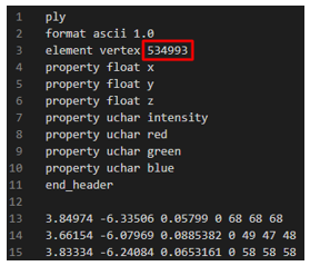
Save the file so that it has the .ply file name extension.
Import the .ply file
Open Houdini. A new scene is automatically created. In this procedure, you'll build a chain of nodes to process the point cloud into a 3D object. These nodes are built in the lower-right pane of the Houdini window.
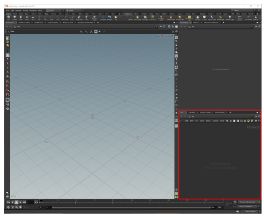
Right-click in the lower-right pane to open the TAB Menu. (Alternatively, press the Tab key.)
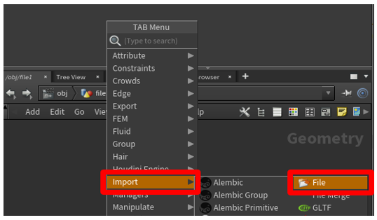
On the TAB Menu, select Import > File, and then select in the Geometry pane to place the node.
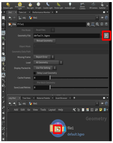
Double-click in the middle of the file1 node (or press I) to drill down into the file selection part of the node, select the File Chooser button, and then select the file to import.
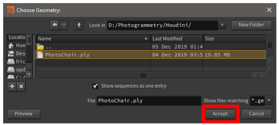
In the file browser that appears, browse to the location of the .ply point cloud file that you want to import, select the file, and then select Accept.
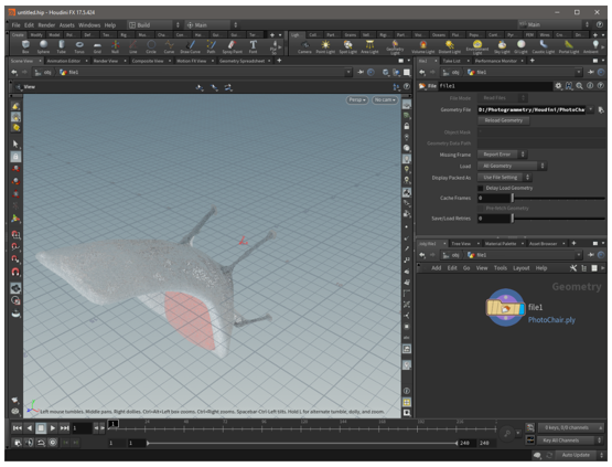
The point cloud appears in the main part of the window. If you can't see it, try to use the mouse wheel to zoom out until you can see the whole point cloud.
Prepare the point cloud
Reorient the point cloud
Sometimes, when you first import a point cloud, it has the wrong orientation. You can fix the orientation by adding a transform node to the node tree.
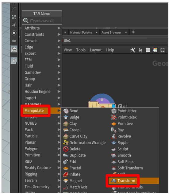
Right-click in the Geometry pane to open the TAB Menu, and then select Manipulate > Transform to add a transform node.
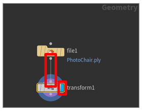
Drag from the dot on the bottom of the file1 node to the dot on the top of the transform1 node. In this way, you connect the output of the file1 node to the input of the transform1 node. Then select on the right side of the transform1 node. The right side of the transform1 node becomes blue, and the node becomes active in the main part of the window, so that you can see your model after it has been reoriented.
Tip
To view the model during a specific stage of the process in Houdini, click on the right side of the appropriate node. This capability is helpful if you ever have to look at your 3D object in a previous state and edit the changes that occurred during that state.
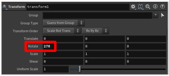
To correct the rotation of your model, in the options pane above the node pane, add values in the Rotate row. You can often set the x value to 270 to rotate the model to the correct position. However, if that value doesn't work, try different values.
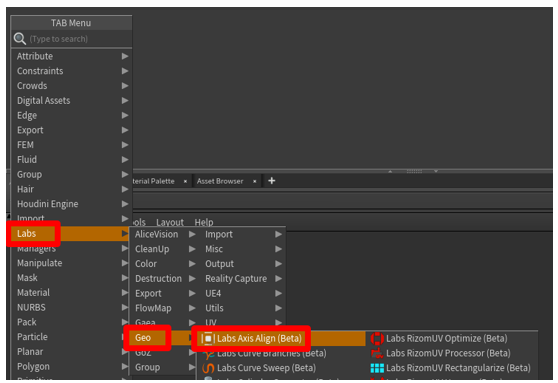
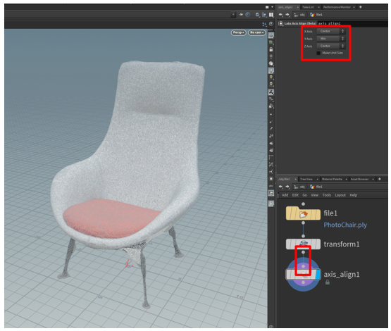
To center your point cloud over the origin point, add an axis align node after the transform node. To place the node, hover your mouse over the Geometry pane, press the Tab key to open the TAB Menu, and then select Labs > Geo > Labs Axis Align.
Drag to connect the output dot on the bottom of the transform1 node to the input dot on the top of the axis_align1 node. Leave the default values as they're to position your point cloud on top of the origin point (an ideal place for it).
Clean up the point cloud to remove stray points
If your point cloud has stray points that you want to remove, you can select and delete individual points or groups of points.
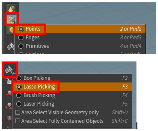
Change the Geometry select method to Points and the Select tool to Lasso Picking.
Note
You can use a different method if you prefer.
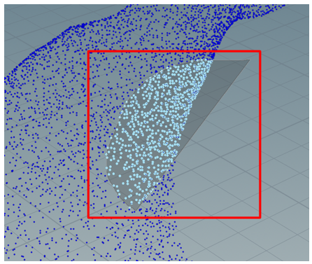
Select the points to delete.
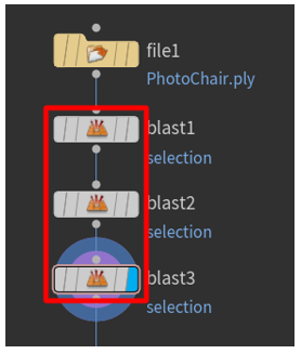
Press the Delete key. A new blast1 node appears. The input dot on the top of this node is connected to the output dot on the bottom of the last node that you were working with.
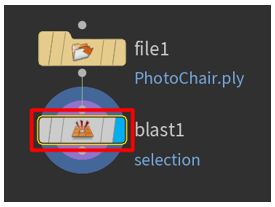
Continue to remove points until you're satisfied with the results. Each deletion adds a new blast node that you can view or remove at any time.
Convert the point cloud to a mesh
Both glTF and real-time rendering applications require that objects be represented as a triangulated polygon surface. You can use the Particle Fluid Surface command to connect the points into a logical surface as polygonal geometry.
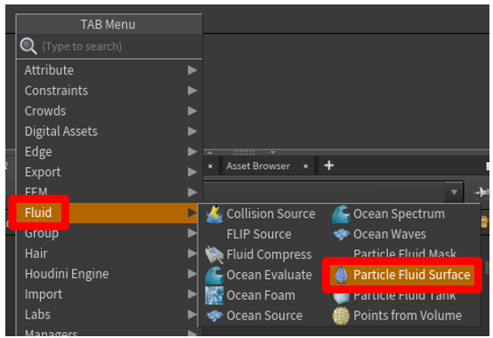
Select in the Geometry pane to open the TAB Menu, and then select Fluid > Particle Fluid Surface. Then select the node, and add it to the Geometry pane.
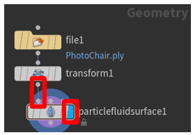
Drag to connect the output dot on the bottom of the transform1 node to the input dot on the upper left of the particlefluidsurface1 node. Then select on the right side of the pariclefluidsurface1 node to activate the node in the main part of the window.
In the main part of the window, the point cloud is rendered as a mesh. The Surfacing tab is selected in the upper-right pane above the Geometry pane.
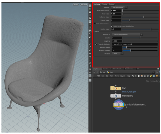
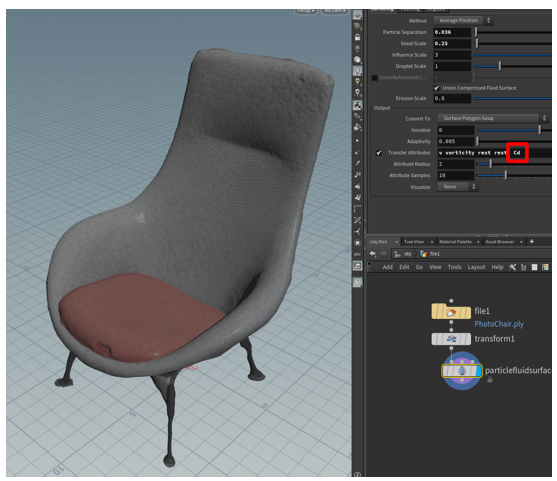
If color data is associated with the points in the point cloud, you can use the color attributes by adding the letters Cd to the end of the value in the Transfer Attributes field. The color will then be shown on your mesh.
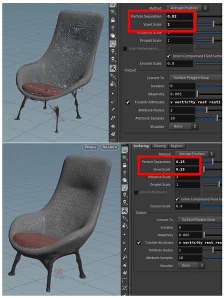
If there are holes in the mesh, as shown in the following illustration, adjust the Particle Separation and Voxel Scale sliders in the upper-right pane to try to fix the issue.
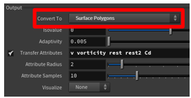
To prepare the mesh for decimation (the next step in the overall process), under Output, change the value of the Convert To field from Surface Polygon Soup to Surface Polygons. In this way, you can remesh the mesh and decimate it.
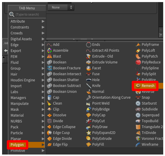
Right-click in the Geometry pane to open the TAB Menu, and then select Polygon > Remesh. A remesh node is added to convert the mesh to triangles. In this way, you can decimate the 3D object to a polygon count that meets your performance requirements.
Drag to connect the output dot on the bottom of the particlefluidsurface1 node to the input dot on the upper left of the remesh node. Select in the middle of the remesh node to activate it in the pane above the Geometry pane. Then select on the right side of the remesh node to activate the model in the main part of the window. You can now edit the properties of the remesh, and the model in the main part of the window will reflect those edits.
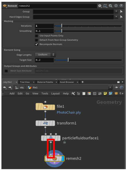
Experiment with the options under Element Sizing to get the results that you want. For the Edge Lengths field, you can keep the default value (Uniform), or you can select Adaptive and adjust the Relative Density slider (and other options) to produce the mesh that you want.
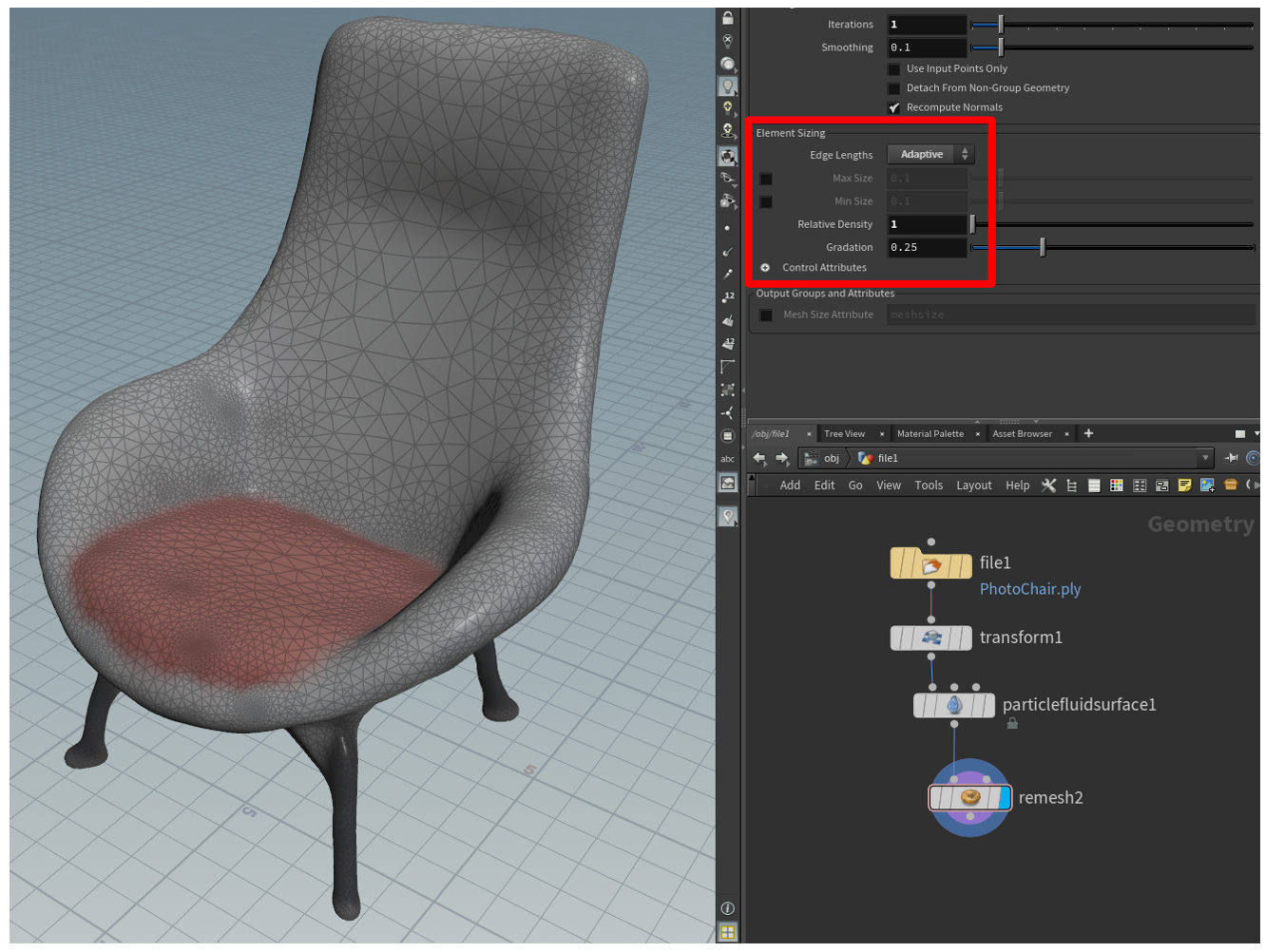
Decimate the 3D object to help improve performance
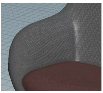
To achieve application-specific goals, you might have to decimate your 3D object. Decimation is the process of recomputing the surface polygons of a model to create a similar shape by using fewer polygons. Although this process reduces visual fidelity, it helps improve performance. The following table shows a side-by-side comparison of a high-quality model that is used for low-scene complexity on HoloLens and a low-quality model that is used for high-scene complexity.
| High-polygon 3D object | Low-polygon 3D object |
|---|---|
 |
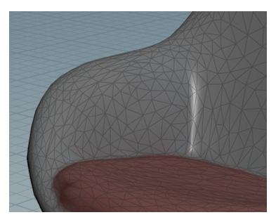 |
| 500,000 triangles | 8,000 triangles |
Decimate a model
In the Geometry pane, press the Tab key to open the TAB Menu, and then select Polygon > PolyReduce to place a PolyReduce node in the Geometry pane.
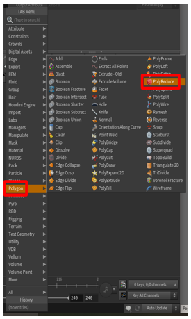
Drag to connect the output dot on the bottom of the remesh node to the input dot on the upper left of the polyreduce1 node. Select in the middle of the polyreduce1 node, and then select on the right side of the node to activate it in the main part of the window.
Under Reduction Amount, in the Target field, select Output Polygon Count, and then use the Number To Keep slider to adjust the polygon count to meet your performance requirements but also maintain acceptable visual fidelity.
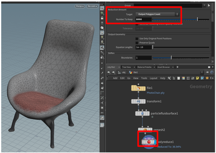
The point cloud has now been converted to an optimized 3D mesh. In the next step, you'll bake a high-resolution texture onto the 3D object to recover some of the visual fidelity that existed before decimation.
Bake a high-resolution texture onto a low-polygon mesh
One downside of reducing the number of polygons in a mesh is that much of the detail might be lost. To restore some of that detail, you can capture it and apply it as a texture that is layered on top of the low-polygon model. During this process, which is known as texture baking, you take a picture of all the surfaces from your high-polygon model and join them into a "quilt" that you drape on top of the low-polygon model. In this way, you gain the performance of a low-polygon model but maintain some of the finer details of a high-polygon model.
Texture coordinates (also known as UVs) are pairs of numbers (U and V) that are stored in the geometry of a model. These numbers represent that way that a 2D image can be mapped to a 3D surface, and enable surface properties to be defined as an image. The images can be simple decals or complex material components, such as roughness and metallic. You can manually generate UV positions for a mesh, or the process can be done semi-automatically or automatically. The AutoUV surface operator is one tool in Houdini that can generate UVs. It uses a few automatic methods during the creation of UVs.
Bake the texture
Right-click in the Geometry pane to open the TAB Menu, and then select Labs > UV > Labs Auto UV to add an AutoUV node to the scene.
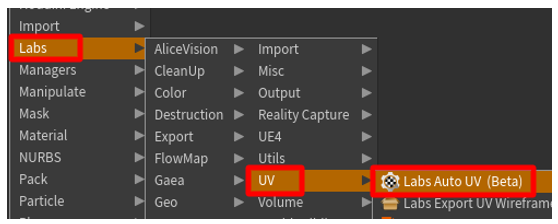
Under Method, change the value of the Method field to UV Unwrap.
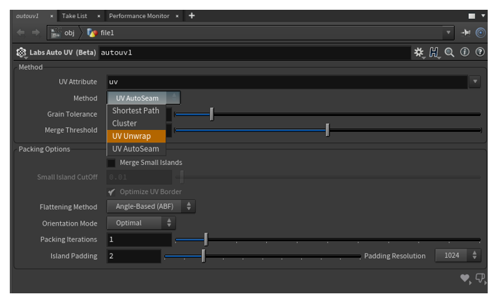
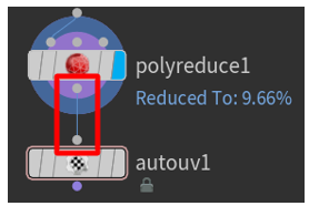
Drag to connect the output dot on the bottom of the polyreduce1 node to the input dot on the top of the autouv1 node.
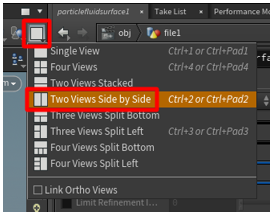
To view the "before" and "after" objects side by side, select the Viewport Layout button, and then select Two Views Side by Side.
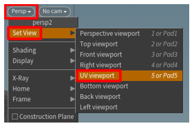
In the main part of the window, on the drop-down menu, select Set View > UV viewport.
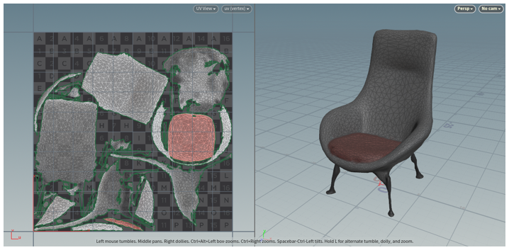
The unwrapped UVs appear on the left, and the 3D object appears on the right.
In the Geometry pane, select Labs > Output > Labs Maps Baker to add a maps_baker1 node.

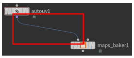
Drag to connect the output dot on the bottom of the autouv1 node to the input dot on the upper left of the maps_baker1 node. (The upper-left dot is the LOW Resolution input node.)
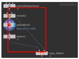
Drag to connect the output dot on the bottom of the particlefluidsurface1 node to the input dot on the upper right of the maps_baker 1 node. (The upper-right dot is the HIGH Resolution input node.)
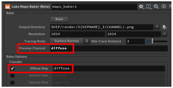
Select the maps_baker1 node, and then, under Bake, change the value of the Preview Channel field to diffuse. Under Bake Options, set the Diffuse Map field to diffuse.
Tip
To save your project in a specific folder, select the File Chooser button next to the Output Directory field that is shown in the previous illustration. When you bake a texture, the .png texture file is saved to a render folder that is created in the root folder of the saved project. By saving your project in its own folder, you make the baked texture easy to find.
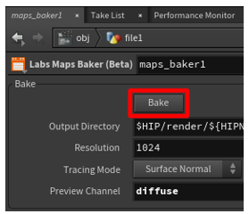
Select the maps_baker1 node, and then, in the options pane, select Bake.
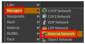
Right-click in the Geometry pane to open the TAB menu, and then select Managers > Material Network to add a matnet1 node to the scene.
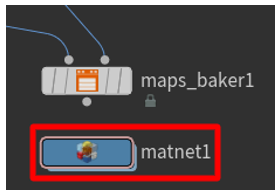
Double-click the matnet1 node to open the VEX Builder pane.
Right-click in the VEX Builder pane, and then select Shaders > Principled Shader to add a Principled Shader material.

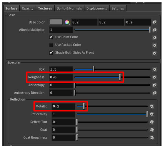
In the options pane, on the Surface tab, use the sliders to change the value of the Roughness field to 0.6 and the value of the Metallic field to 0.1. (You can set these fields to whatever you want, but we have found that these values are a good starting point when they're used with the default values.)
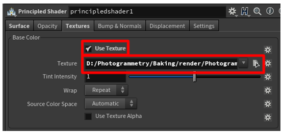
On the Textures tab, under Base Color, select the Use Texture check box. Then select the File Chooser button, and select the *_color.png texture file that you saved to the render folder earlier. The principled shader is now ready to use.
Note
Feel free to modify the material further. For the purpose of this tutorial, this configuration is sufficient.
In the VEX Builder pane, select the Back (left arrow) button to return to the Geometry pane.

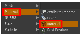
Select Material > Material to place a material node in the Geometry pane.
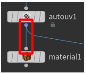
Drag to connect the output dot on the bottom of the autouv1 node to the input dot on the top of the material1 node.
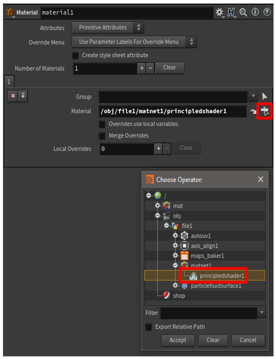
Select the material1 node, and select the Operator chooser button. Then, in Choose Operator dialog box, select file1 > matnet1 > principledshader1 to select the principled shader that you created earlier.
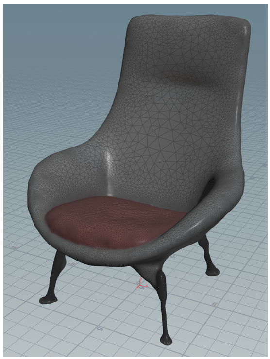
Select on the right side of the node to activate it in the main part of the window.
The texture is rendered on top of your low-polygon 3D object. If it looks acceptable, move on to the next step.
Export the model to a .glb file
In this step, you'll export the model to a .glb file so that it can be used with Dynamics 365 Guides and Power Apps.
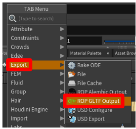
Right-click in the Geometry pane to open the TAB Menu, and then select Export > ROP GLTF Output.
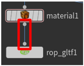
Drag to connect the output dot on the bottom of the material1 node to the input dot on the top of the rop_gltf1 node.
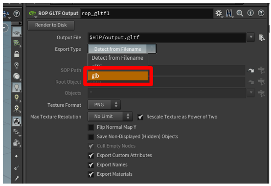
In the upper pane, change the value of the Export Type field to glb.
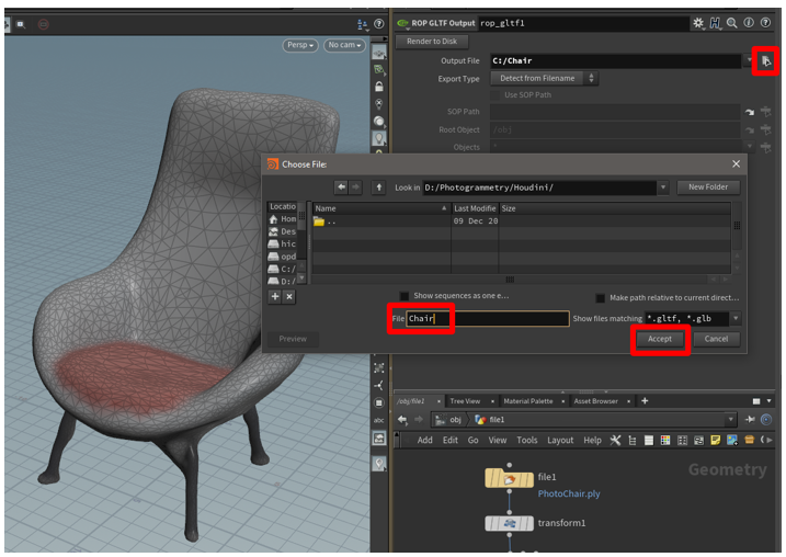
Select the File Chooser button next to the Output File field, and then enter a name and destination for the .glb file. Be sure to add .glb to the end of the file name. When you've finished, select Accept.
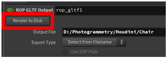
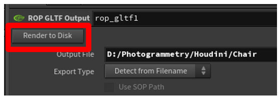
Select Render to Disk to finalize the export and create the .glb file.
Create a template to reuse your settings for other point clouds
To save time and effort, you can create a template. In this way, the settings that you create for a point cloud can be used for other point clouds. Although you must still manually select Bake and will probably have to adjust a few values, you can automate most of the processing.
Create a template
Replace the geometry that is currently being used with a default geometry. This step makes the template file lightweight, so that it's loaded quickly.
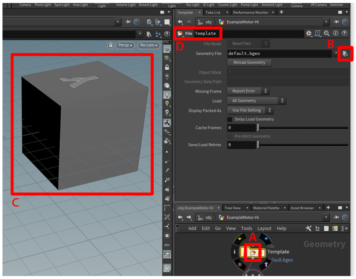
In the Geometry pane, select in the middle of the file node to switch to the File menu in the upper pane.
Change the value of the Geometry File field to default.bgeo, and then select Reload Geometry.
Notice that the geometry is redrawn so that it's now a generic cube.
Change the file name to something generic, such as Template.
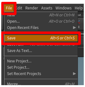
Select File > Save, and enter a name that you'll remember, such as Prep_Template.
Close Houdini.
Use the template
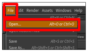
Open Houdini, select File > Open, and then select the template that you just created.
In the Geometry pane, select in the middle of the file node to switch to the File menu in the upper pane. Then select the File Chooser button next to the Geometry File field to select the .ply point cloud file.
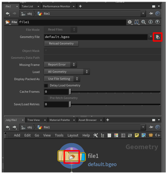
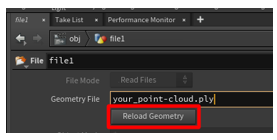
Select Reload Geometry to load the point cloud into the scene.
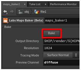
Go to the maps_baker1 node, and then select Bake to bake a new texture for your 3D object.
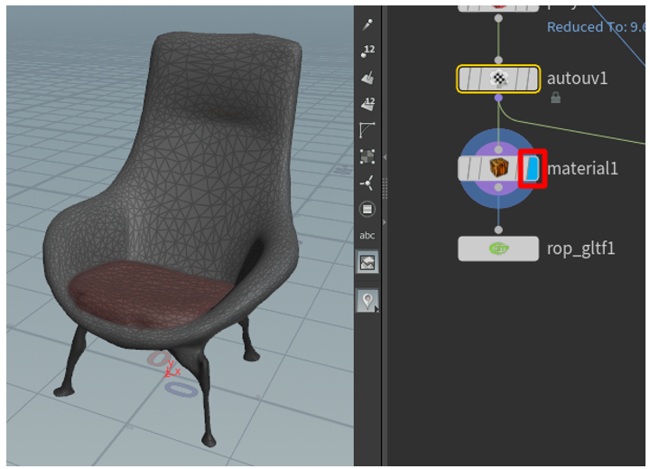
Select on the right side of the material1 node to view your baked model.
Follow one of these steps:
If you're satisfied with the 3D object, go to the rop_gltfB node, and then select Render to Disk to export your 3D object.
If you aren't satisfied with how the 3D object looks, adjust the settings for the particlefluidsurface1, remesh, and polyreduce1 nodes. When your model looks acceptable, bake your texture again, and export the 3D object.
View a 3D object in Dynamics 365 Guides or Power Apps
After you've prepared a 3D object, use the following links to learn more about using the model in Dynamics 365 Guides or Power Apps:
More information
Screenshots in this tutorial were taken from the Houdini software program to provide clear instructions about how to use the Houdini software. Learn more about SideFX Houdini.
Microsoft Corporation isn't responsible for, and expressly disclaims all liability for damages of any kind arising out of the use of Houdini, or reliance on these instructions. This document is created only to provide general information to our customers and doesn't take into consideration any individualized business plans or specifications.
The use in this document of trademarked names and images is strictly for informative and descriptive purposes, and no commercial claim to their use, or suggestion of sponsorship or endorsement, is made by the Microsoft Corporation.
Feedback
Coming soon: Throughout 2024 we will be phasing out GitHub Issues as the feedback mechanism for content and replacing it with a new feedback system. For more information see: https://aka.ms/ContentUserFeedback.
Submit and view feedback for