Overview
.jpg)
Autogen
Autogen is the ESP process that generates the default scenery objects. The simulated world is divided into a grid, each square roughly 1.2 by 1.2 kilometers, and each grid square will have a texture applied to it based on its land classification (see the Terrain and Scenery documentation for details). The textures for land classification can have an associated annotation file, which contains footprints of buildings and vegetation. If a specific building model is required, then a library object can be placed on the texture. However, for the majority of buildings this would result in a very repetitive landscape. For this reason, only the footprint, range of heights, and building textures are contained in the annotation file. The Autogen process will select or construct an appropriate building model at run time, therefore creating much more varied and realistic landscapes.
This document explains how to annotate textures with buildings and vegetation, and modify or replace default scenery textures. Note that many of the SDK tools require the ESP client to be installed on the same computer as the SDK.
See Also
Table of Contents
Annotating Textures
Setup
The Control Strip
Creating Building and Vegetation Footprints
Setting Building Properties
Autogen Texture Sheets
Layout of Building Texture Sheets
Layout of Row Houses Texture Sheets
Layout of Polyline Building Texture Sheets
Library Object Texture Sheets
Use of Imagetool with Building Textures
Autogen Configuration Editor
Vegetation Groupings
Editing the Default.XML file
- Tutorial: Adding a New Autogen Class
- Editing the Default.XML file by hand
- Excluding Autogen Objects
Editing the AutogenDescriptions.XML file
- Vegetation Groupings
- Tutorial: A Tree for All Seasons
- Hints on Creating Tree Models
Autogen Validation Tools
Creating an SPB file
Annotating Textures
Textures are annotated using the annotator.exe tool.
- Setup
- The Control Strip
- Creating Building Footprints
- Setting Building Properties
Setup
- To use the tool, make sure the file default.XML is in the same folder as Annotator.exe. The default.XML file is in the Microsoft ESP\1.0\Autogen folder.
- The Control Strip of the tool requires a screen resolution of at least 1280 by 960.
- When the Annotator tool is first started, the Autogen Configuration Editor, and a number of other windows will appear. Do not attempt to close the Autogen Configuration Editor dialog, but if screen space is crowded the other windows such as Find Results, Find, Properties, Groupings, and Model Entries, can be closed, and re-opened if necessary using Configuration Editor menu selections (Edit/Find or View/Windows). The Autogen Configuration Editor window can be resized to minimize its screen area.
The Control Strip
The Control Strip is a floating window that may be positioned anywhere on the desktop. You can use the Control Strip to select the annotation editing mode. The mode selection determines the action of your mouse. Using these modes, you can create building and vegetation footprints, place library objects and row houses, and also pan textures and select and manipulate objects.
Building (B), Row Houses (R), Polyline Building (J), Library (L), Vegetation (V), Polygon Region (I)
Choose one of these modes to create building and vegetation footprints, specific to the region, on the ground texture. See Creating Building and Vegetation Footprints.
Pan (N)
Choose this mode to pan the texture within the workspace. Click and drag anywhere in the workspace to move the visible portion of the image. Alternatively, you can pan the texture in any mode by using the middle mouse button (or mouse wheel button) to click and drag.
Zoom (Z)
Choose this mode to zoom in and out on the texture. To magnify a section of a texture, click the left mouse button anywhere in the workspace. To zoom out, click the right mouse button. You can also zoom in or out in any mode by rolling the mouse wheel up and down.
Select (S)
Choose this mode to select building and object footprints and vegetation areas. To select any footprint or vegetation area, click it. To select multiple objects, hold down the Ctrl key and then click each object that you want to select, or click and drag a selection area. You can then move, cut, copy, paste, or delete the selected objects.
Paste (A)
Choose this mode for a very quick method of pasting selected building footprints, vegetation areas, and library objects onto the texture. Select one of more objects as described above for Select mode, then click Paste (A). Now on the texture, click the left mouse button to paste the selection as many times as desired.
Creating Building and Vegetation Footprints
For Polygon Region(I), Vegetation(V), Polyline Building (J) and Building (B), first select the GUID of the footprints you wish to place, by opening up the appropriate file using the Configuration Editor dialog (which will appear when the Annotator tool is started), and then selecting the object name from the lists presented in the various windows. Click Set Guid in the Control Strip to load the details of that object into the Annotator tool. For vegetation areas refer to the notes in Vegetation Groupings.
On the Control Strip, click Building (B), Row Houses (R), PolyLine Building (J), or Library (L), for buildings, or Vegetation(V) or Polygon Region(I) for vegetation. If a library object is selected, make sure to select the appropriate class of library object before placing the footprint. The classes of library object are in the large list box on the Control Strip, and include Industrial Complexes, Religious Buildings, Urban Buildings and so on. See Editing the default.XML file for details on how to add library objects.
Move the cursor to the place on the image where you want to place a building, and draw a footprint as follows:
.jpg)
Library objects are of a fixed size. To draw a polyline building (such as a building with a courtyard, or with an open area in the center) just click on the outline of the building, then right click to select one of the options in the right-click menu to close the polygon, then move the mouse and click again to finalize the shape and size of the building. Note that polyline buildings must be completely enclosed (so for example, it is possible to create a Pentagon type building, but not a U shaped building using this feature). Individual building footprints are shown in red, row house footprints are in purple, polyline buildings are in violet, and library objects are in light blue. Vegetation areas are outlined in green, polygon regions are outlined in red, but fill with green.
The Select button can be used to change footprints from one selection to another. Select the footprint that you wish to change, so that it is highlighted in yellow. Then select the model entry or grouping that the footprint should be changed to, then click on Set Guid -- the footprint will then be changed to reference the new object.
Repeat steps 2 through 4 until you have drawn a footprint for each building, row house or vegetation area that you want Autogen to draw. There is no limit to the number of footprints. To reduce the workload involved with placing many footprints of similar size, you can use the copy, paste, and delete functions available. You can copy and paste an individual footprint or a group of footprints. To copy and paste footprints: click Select on the Control Strip, and then click on the footprint that you want to duplicate. Footprints turn yellow when selected. To select multiple footprints, hold down the Ctrl key while clicking on the footprints. Then, on the Edit menu, click Copy to copy the selection to the clipboard, and then click Paste to paste the selection. Select and drag the new buildings to the desired location. To delete a footprint select the footprint that you want to delete, and press the delete key.
Check for intersecting footprints. Autogen prevents automatically generated objects from overlapping custom-placed objects, but it cannot prevent footprints from intersecting with one another. Therefore, you must make sure that footprints do not intersect. To check for intersecting footprints click Highlight Intersects on the Control Strip. Intersections are highlighted in orange, as shown in the diagrams below (where a row house and a building intersect). Note that it is not possible to select a large vegetation area, and then place buildings on that area: Autogen buildings do not punch out an appropriate space in Autogen vegetation. Vegetation and building footprints should not intersect, however only intersections between polygon regions and buildings will be highlighted. Rectangular vegetation areas and polygon vegetation regions are allowed to intersect with each other, even if they are of a different type.
Set the properties for the buildings, see Setting Building Properties.
On the File menu, click Save. An annotation file (with the extension .agn) will be saved to the same directory that the original image is in. If there is no existing annotation, a new file will be created. Any existing annotation file of the same name will be overwritten. It is a good idea to save often as you annotate each file, as creating all the footprints can be a slow and painstaking process.
When you have finished, your image might look something like the following image, where every colored block represents a building or piece of vegetation that will be rendered in ESP.
.jpg)
Note
Polyline vegetation is rasterized into a sampling bitmap. The granularity of the rasterization is determined by the following setting in the ESP.cfg file:
[TERRAIN] IMAGE_PIXELS_FOR_AUTOGEN_POLYGONS=16The value of this setting is set at the minimum, 16, and can be any value up to 2048. The higher the number the more accurately a curved polygon will be rasterized. The value 16 indicates a rasterization of approximately 80 meters down to approximately 0.5 meter accuracy for the 2048 setting. There is a performance penalty with the time it takes to rasterize a region, and the memory required for the resulting sampling bitmap.
Setting Building Properties
To set properties that control the runtime generation of buildings, use the options in the Annotation Properties dialog box (in the File menu of the Annotation tool, click Properties).
.jpg)
Height Profile
Use the height profile sliders to set the building height profile for the current texture. The height of each building is generated at runtime, but these sliders control the height profile. The further to the right each slider is, the more buildings of that type are generated.
For example, in a typical suburban ground texture, most of the buildings have 1 or 2 floors, a few buildings have 3 to 8 floors, and no buildings have 9 or more floors. To create this building height profile:
- Move the 1-2 floors slider to the far right to increase the proportion of buildings with 1 or 2 floors.
- Move the 3-5 floors and 6-8 floors sliders toward the left to decrease the proportion of buildings with 3 to 8 floors.
- Move the 9-12 floors slider to the far left to prevent the generation of buildings with 9 or more floors.
Similarly, in a more urban or industrial ground texture, move the sliders that control the taller buildings to the right, and move the sliders that control the shorter buildings to the left. Fundamentally, the slider values represent the relative probability that a particular height will be selected for each individual building footprint. However, to prevent the creation of oddly sized buildings, there are two exceptions: if a building footprint is either small (less than 625 square meters) or very large (greater than 1600 square meters), the height will be forced to one or two stories at runtime.
Building Texture
Use the Building Texture list to select the bitmap that will be used to texture the buildings. You can modify the default texture or create new Autogen building textures. For more information, see Autogen Texture Sheets.
RowHouse Texture
Use the RowHouse Texture list to select the bitmap that will be used to texture any row houses. You can modify the default texture or create new Autogen row house textures. For more information, see Autogen Texture Sheets***.***
Restore Last Settings
If you want to reset the slider values for the texture to their original settings, click this button.
Autogen Texture Sheets
Autogen uses a number of texture sheets to define the appearance of buildings and vegetation. These texture sheets take advantage of as much texture space as possible to deliver the maximum amount of visual difference in how Autogen objects appear, while remaining a minimal burden on texture memory resources. Autogen uses four classes of textures: building, row houses, library and vegetation. You can edit these textures to customize the appearance of the default scenery. These four texture classes have different layouts, which are described in the following sections.
- Layout of Building Texture Sheets
- Layout of Row Houses Texture Sheets
- Library Object Texture Sheets
Layout of Building Texture Sheets
In the ESP\texture folder there are a number of texture sheets for Autogen buildings that represent day and night variations of buildings in different regions of the world. Each texture map is constructed to follow a consistent layout, regardless of the time of day or location. The following diagrams illustrates the basic layout of a building texture, and the layout in pixels.
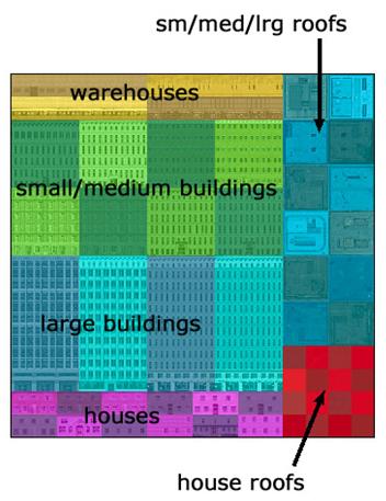 |
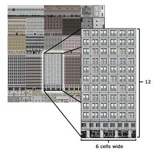
Textures are mapped to buildings that meet certain constraints. For example, only buildings that fit a certain profile (building footprint, building height) will be textured with one of the four warehouse texture variations (color-coded yellow above). Autogen building texture sheets are 512 x 512 pixels in total size. However, individual texture areas that describe the sides of a building are formed by smaller subunits called cells. Cells are 16 x 16 pixels in size. On a building side texture, one cell is equal to approximately one story of building height and an equal measurement in the building’s width. Roof textures are composed of single cells. Depending on the vertical height, length, or width of a particular building, Autogen clips to the nearest cell.
For example, in the diagram below, Autogen uses the entire 6 cells of available width on one side, 4 out of 6 cells on another side, and 8 out of 12 cells of height. In the building in the background, 9 out of 12 cells of height are used.
 |
.jpg) |
For house roof textures there is a RoofDescriptions.XML file that includes regional information and variations on house roofs. House roof texture files that are referenced from the RoofDescriptions.XML file can have a varied format (the texture co-ordinates are in the XML file).
Layout of Row House Texture Sheets
In the root ESP\texture folder there are a number of texture sheets for Row House buildings. The following diagram illustrates the basic layout of the textures.
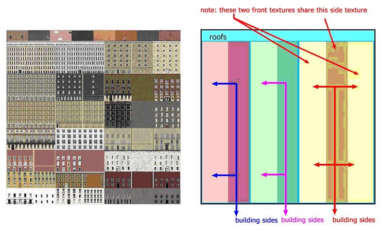 |
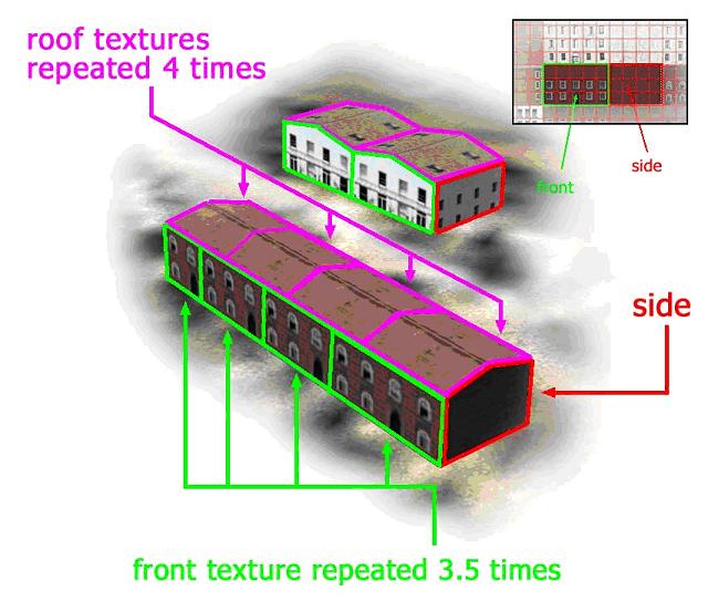
Textures are mapped to buildings that meet certain height constraints. Unlike the default Autogen buildings that use a tiling texture that wraps around all sides of a building, all Row House buildings use two textures. The first texture (designated as “front” in the figure above) is used to texture the longest sides of the building, and the second texture (designated as “side”) is used to texture the shortest sides. An additional difference between Row House textures and default buildings lies in how the roofs are textured in each. Default buildings select from a variety of roof textures based on building type and size. Row House buildings select one roof texture from a pool of equal sized textures regardless of building size. Row House building texture sheets are 512 x 512 pixels in total size.
The next illustration demonstrates how Row House textures are tiled across the face of a given side or top of a building. On the Row House texture sheet, there is a 3 x 4 cell area of unique texture available for the front of a building that fits this height profile, and a 3 x 4 cell area for the side. In the nearest building below, Autogen uses an entire 3 x 4 cell area of available width and height for the front of the building, and tiles that group of cells 3.5 times across the length of the building. The side of the building also uses a different 3 x 4 cell area, but only for one instance. The roof of this building uses one roof cell tiled 4 times. Depending on the length or width of a particular building, Autogen clips to the nearest cell. In the building in the background, a 3 x 4 cell area is tiled twice across the long face, once across the side, and twice along the top. Because Row Houses have roofs that are pitched across either the long front or the short side, there is a small amount of texture clipping in the cell area adjoining the roof (see the second illustration below).
 |
.jpg) |
Layout of Polyline Building Texture Sheets
The Polyline building is a new type of Autogen object introduced in ESP, and is most often used to render courtyard-type buildings. These objects are extruded from a two-dimensional profile generated by an art tool such as 3dsMax. There are nine basic profiles from which all of the polygon Autogen buildings are created. The profiles simulate three different roof types and each type comes in three different heights – three stories, four stories and five stories. Each profile also includes a one story basement section. There are two or three textures assigned to each courtyard building – either one or two roof textures, and a side texture. Polyline buildings do not get specular or normal maps but do get a night map.
Side Textures
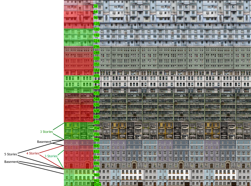
The side texture is a tiling 1024x1024 texture that incorporates 32 floors with each floor occupying 32 pixels vertically and 1024 pixels horizontally. The floors are arranged vertically in such a way that the specific sections of the texture can be mapped to 3-story, 4-story or 5-story courtyard buildings (shown in red in the image below). In other sections the only mapping allowed is to a 3-story building (shown in green). In all cases, one additional story is mapped to the basement of the building. There are two variations of each side texture for each of the 26 world regions (refer to the Terrain and Scenery document for a description of the regions), for a total of 52 variations. Roof textures are not regionalized. The side textures should be saved as a DXT1 (without alpha) DDS. These textures have a BLD_ prefix followed by a regional designator and a version number (for example BLD_Europe_North_1.dds).
 |
Roof Textures
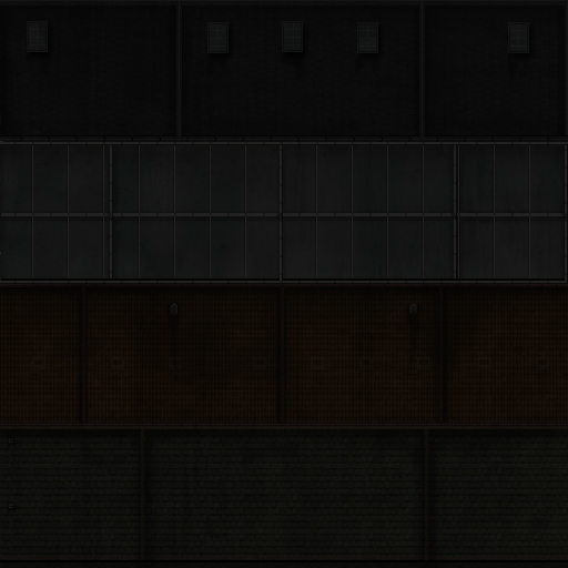
Polyline roof textures come in two flavors: sloping roof textures and flat roof textures. The sloping roof textures are intended to map to the angled sides of peaked and mansard style roofs. The flat roof textures are intended to map to the flat top sections of mansard style roofs and also to flat roofed buildings. Each texture is a 512x512 DXT1 without alpha in DDS format, and is divided into four individual roof textures occupying 128 pixels vertically and 512 pixels horizontally. These textures tile horizontally but not vertically.
The texture files have a prefix of BLD_roof_ and a “Top” or “Side” indicator in the name (for example: BLD_Roof_Top_L01.dds, BLD_roof_side_K02.dds). There are six top variations and six side variations as well as night map versions for each. Buildings with mansard roofs use two roof textures (one side and one top); all others use one roof texture, either one top or one side texture.
.jpg) |
.jpg) |
 |
.jpg) |
.jpg) |
Library Object Texture Sheets
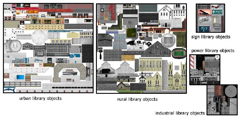
To create a richer visual environment, Autogen can display more complex 3D shapes selected from a library of generic types. Because these objects are more complex, each 3D object has dedicated texture coordinates unique to that object. Some objects may share texture space with other objects (for example, two different motel models may use the same texture of a swimming pool, but the location, shape, and size of the pool can differ in each motel), but even then the texture coordinates are different from object to object. It is possible to edit the textures themselves, but not to change the texture coordinates used by the models in question. The illustration below shows some example texture sheets used for Autogen’s library objects, and the second illustration shows an example of more complex shaped objects.
 |
.jpg) |
Use of Imagetool with Building Textures
To create custom building textures for Autogen, go through the following procedure:
The source textures used for the building layouts described above can be created as .psd, .bmp or .tga files. Use an appropriate art tool to create these texture files.
When the texture files are complete use the Imagetool utility to convert the files to the correct format (Imagetool is in the Environment Kit\Terrain SDK folder but is used in a number of areas throughout the SDK, in particular refer to Panel and Gauge Artwork and Texturing Aircraft Models). For the purpose of Autogen textures, use the following command line entry to Imagetool:
>imagetool -dxt1 -dds -mips filename
where filename is the full path and extension of the source texture file (or just the filename if Imagetool is in the same folder as the source file). Imagetool will create a file called filename.mip.
Rename the file from filename.mip to filename.dds.
The .dds files should be placed in the Microsoft ESP\1.0\Texture folder.
Autogen Configuration Editor
The Autogen Configuration Editor tool can be used to edit many of the files that define the Autogen procedure. In the ESP\Autogen folder there is the default.XML file, and the other files listed here are in the Environment Kit\Autogen SDK\Autogen source xml folder (it these files are edited, then place the new files in the ESP\Autogen folder to be read by ESP).
| AutogenDescriptions.XML | Describes the vegetation groupings and regionalizations. Vegetation models (trees, shrubs etc.) are referenced from within the file. | Yes. Add, remove or modify vegetation groupings and weights, and add or remove individual vegetation model references. See Vegetation Groupings. Care should be taken to make sure all the seasonal variations are added for new models. Note the MaxScale and MinScale parameters are not implemented in this version of ESP. |
| AutogenDescriptions_mid.XML AutogenDescriptions_min.XML |
These are variations of the AutogenDescriptions file that reduce the rendering complexity of the vegetation. Which file is used depends on the AutogenDescriptionsFilename setting in the [Terrain] section of the ESP.cfg file. | Yes. If new groupings or models are added, then they should be referenced in all three descriptions files, otherwise gaps could appear in the scenery during certain seasons, or might occur depending on which descriptions file the user has specified in the configuration file. |
| default.XML | Defines the library objects associated with each region and class of automatically generated scenery. | No. See the section Editing the Default.XML file. |
| Extrusions.XML | Extrusions are vertical objects than are not of a fixed size so cannot be defined by individual models, such as fences and extrusion bridges. | No. To add extrusions as scenery, use the BGL Compiler. |
| Materials.XML | This file contains references to materials used by the other XML files. | Yes. Add or modify materials. |
| RoofDescriptions.XML | Describes the default roofs to use for the various buildings. | Yes. Similar to vegetation. Add, remove or modify groupings and weights, and add or remove individual model references. |
| TerrainAutogenClassDescriptions.XML | Describes the default land classifications. | No. It is not recommended that this file is changed. |
Editing the Default.XML File
The default.XML file defines the library objects associated with each region and class of automatically generated scenery. It can be edited with the AutogenEditor tool (not to be confused with the AutogenConfigEditor tool). The following tutorial goes through the entire process of adding new models and classes to the default.XML file, and then testing those new models in ESP itself. It is quite an involved process, involving a minimum of four tools.
Tutorial: Adding a new Autogen Class
In this tutorial a new class, Cones, will be added to Autogen, with a couple of suitable models. Models within a class appear at random, so the more models that are added to a class, the more varied the landscape. However, for the purpose of this tutorial we will create just two models, and these will be very simple and somewhat unsightly, in order to focus the tutorial on the Autogen tools, and not on the creation of models (see the New Aircraft Procedures and the Texturing Aircraft Models document for information on how to create good 3D art).
3ds Max 8 is used in the tutorial to create the models, the screen shots and procedures will vary slightly for other art tools. Make sure that you are using the latest version of the SDK tools.
Step 1: Create two cone models
Ensure that the Setup procedures have been correctly followed to install the ESP tools, refer to the Setup section of the Using Modeling Tools document.
Open up 3ds Max, select the Customize menu, then select Units Setup. Ensure that the Display Unit Scale is in meters. Select System Unit Setup and ensure the System Unit Scale is 1 unit to 1 meter.
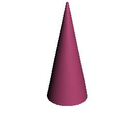
Click one of the simple object types, such as Cone, and create a simple cone, say 40 meters tall with a radius of 10 meters. Do not add a texture to the cone, but color it in some obvious color (pink perhaps). Save off the file with a name such as PinkCone.
Select the Aces Tools menu and click the ExportLOD tool. When the dialog opens click Create new GUID for this file. The Friendly Name field should match the filename we are going to use, so this should be PinkCone. Close the ExportLOD tool.
To verify that a Friendly Name and Guid have been applied correctly to the file, select the File menu -> File Properties -> Custom tab, and these two Name Value pairs, with Type text, should be in the properties section.
Click Export on the File menu. Save as type must be set to ESP 1.0 DirectX File(*.X). Click Save. Click Yes to Export as FSX. Click OK in the ESP Model Export Options dialog, without changing any of the settings. If we had a more complex model, with skins and animations, then these items should be checked, but as we have a simple cone leave them unchecked.
If any export error appears, correct the problem before going any further. Common errors are missing Guids or model units are not in meters.
This should have correctly exported one model, the PinkCone.
Before creating a second model it is a good idea to grab a screen shot of the cone. This can easily be done by a screen capture, pasting into Microsoft Paint, and then cutting out a picture of the cone. A good size is 256 x 256 pixels, and save the file as PinkCone.jpg. This file will be used as a thumbnail picture of the model in a later tool.
Select File -> New in the main menu, then repeat steps 3 to 9 to create a second model, say a PurpleCylinder. When this has been completed you should have exported two .X files, and created two thumbnail images of the models, for example:
.jpg)
Copy the two jpg thumbnails to the Environment Kit\Autogen SDK\Renders folder.
Copy the two .X files to the Environment Kit\Modeling SDK\3DSM7\Plugins folder.
Step 2: Convert the .X files to .MDL files
- Open up a Command Line window and navigate to the Environment Kit\Modeling SDK\3DSM7\Plugins folder.
- Type the following:
>XtoMdl /DICT:..\..\bin\modeldef.XML /XMLSAMPLE PinkCone.X - Type the following:
>XtoMdl /DICT:..\..\bin\modeldef.XML /XMLSAMPLE PurpleCylinder.X - If there are any reported errors with the models, go back to Step 1 and fix them.
- Refer if necessary to the instructions in Using Modeling Tools for using the XtoMdl tool.
- Copy both .MDL files to the Environment Kit\BGL Compiler SDK folder.
- Copy one of the sample placement XML files to the Environment Kit\BGL Compiler SDK folder, and rename it Cones.XML.
Step 3: Create a BGL file containing the two models
- Navigate to the Environment Kit\BGL Compiler SDK folder.
- Edit the Cones.XML file copied across in the previous step, or simply create a new XML file called Cones.XML, so that it contains only the following:
<?xml version="1.0" encoding="ISO-8859-1" ?> - <FSData version="9.0" xmlns:xsi="http://www.w3.org/2001/XMLSchema-instance" xsi:noNamespaceSchemaLocation="bglcomp.xsd"> <ModelData sourceFile="pinkcone.MDL" /> <ModelData sourceFile="purplecylinder.MDL" /> </FSData> - Drag the Cones.XML file onto the BGLComp.exe icon. If all is correct the file Cones.BGL will be created. If this file is not created, open a Command Line window, navigate to this folder, and run the BGLComp tool from command line as this will mean that you will be able to read the reported errors.
- Copy the Cones.BGL file to the Environment Kit\Autogen SDK folder.
- Copy the Cones.BGL file to the Microsoft ESP\1.0\Addon Scenery\scenery folder.
- Refer if necessary to the instructions in Compiling BGL.
Step 4: Add the new class to the Default.XML file
Copy the Default.XML file from Microsoft ESP\1.0\Autogen folder to the Environment Kit\Autogen SDK folder.
Navigate to the Environment Kit\Autogen SDK folder.
Open up the AutogenEditor.exe.config file in a text editor, such as Microsoft Notepad or Visual Studio. Find the following entry and add the text in bold (note the semicolon):
<setting name="ObjectsPath" serializeAs="String">
<value>%ProgramFiles%\Microsoft ESP\1.0\Scenery\Global\Scenery\Autogen.bgl;Cones.bgl</value>
</setting>Save off this file.
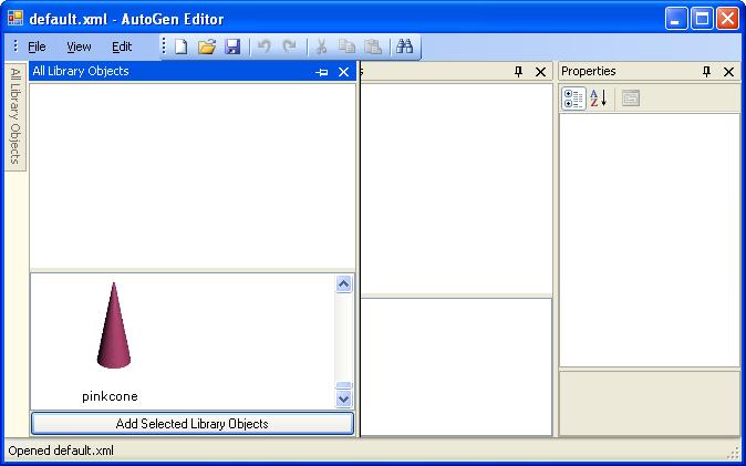
Click on the AutogenEditor icon and open up this editor. Be careful not to confuse this with the AutogenConfigEditor tool.
Click on View -> Windows -> All Library Objects. Click on the All Library Objects tab on the left side of the dialog and verify that the PinkCone and PurpleCylinder models have been pickup up by the tool. The thumbnail icons prepared in step 1 should now appear at the very end of all the library objects.
If the names of the new models appear, but not the thumbnails, ensure that the thumbnails have been named correctly. If the names of the new models do not appear, then check the Cones.BGL file is in the correct location.
Group select all the regions in the Regions box, so that they are all highlighted. Note that a long list of classes appears in the Classes box. Right click on the Classes box and select Add. This will add a new class, called Class, to all the regions. Select Class so that it is highlighted, and its Footprint and Identification properties appear in the Class Properties box.
Change the Depth and Width properties to both be 20. Remember the radius of our models was set at 10 meters, so a depth and width of 20 meters will be required to place the model. With multiple models the depth and width entered here should be the largest of each in both directions, so the footprint is large enough to accommodate any of the models. It is also a good idea to create models to be used with Autogen with a similar sized footprint.
Change the Name field to Cones. Leave the Guid entry untouched.
With the All Library Objects tab open, drag and drop the pinkcone entry into the lower Library Objects box. This adds the one model to the class:
.jpg)
Repeat the drag and drop for the purplecylinder, so that both models are now in the Cones class.
Click Save. This will save off a new Default.XML file. If there are any reported errors, then address them before proceeding.
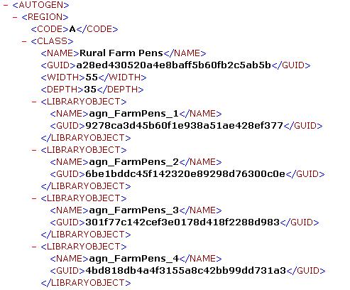
Verify that the new models and class have been added to Default.XML simply be opening up the file, the following entry should appear for each REGION (though note of course that your GUID entries will be different than those below):
- <CLASS>
<NAME>Cones</NAME>
<GUID>88a4b4ff475ce44c614381a2d013b18f</GUID>
<WIDTH>20</WIDTH>
<DEPTH>20</DEPTH>
- <LIBRARYOBJECT>
<NAME>PinkCone</NAME>
<GUID>95be2ae047e5793c67fd16a788fa9a10</GUID>
</LIBRARYOBJECT>
- <LIBRARYOBJECT>
<NAME>PurpleCylinder</NAME>
<GUID>bde51d6d4b6ed09240c85d8e4fdc6592</GUID>
</LIBRARYOBJECT>
</CLASS>It is very important now to copy the new Default.XML file back from the Environment Kit\Autogen SDK folder to the Microsoft ESP\1.0\Autogen folder.
Step 5: Add references to the new class using the Annotator tool
Navigate to the Environment\Autogen SDK folder, and open up the Annotator.exe tool.
On the main dialog (with the title Flight Simulator X Autogen Annotation Tool) select Open, then navigate to and select the Microsoft ESP\1.0\Scenery\World\Texture\024b2su1.bmp file. This particular file is chosen as it is easy to locate when running ESP.
Select Cones in the list of library objects in the Control strip of the tool, then click the Library(L) button. Now use the mouse to add any number, say around 10, of the Cones models to the texture. They should all appear as small light blue boxes on the texture.
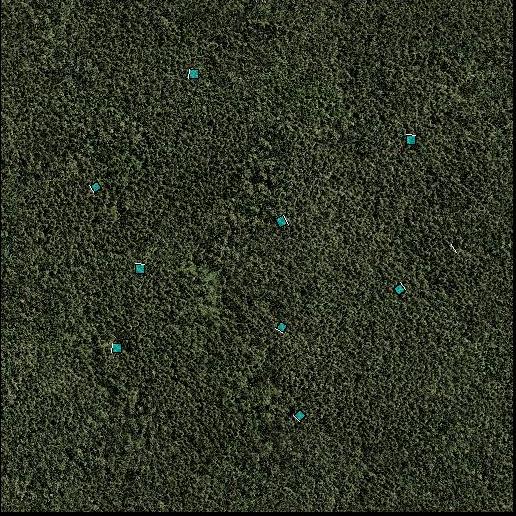
Click Save on the main dialog. This will save off both a new bmp file, and a new Autogen annotation file, to the correct locations.
Step 6: Verify that the new models are rendered
- Start up ESP, and ensure that the Current Location is Sea-Tac International (enter KSEA as the airport ID code), and that the month is a summer month such as July (as we have just annotated a single summer tile).
- Takeoff from Sea-Tac and head due West. The 024b2su1.bmp tile is used frequently in the islands of Puget Sound, and you should see your new models appearing. Note that the actual number that appear depends on Autogen Density settings. Make sure that you fly close enough to the ground so that the models are not culled from the rendering pipeline because of your distance from them.
- If your models are not visible, make sure that your Scenery settings are set to the default or greater density, that the updated Default.XML is in the correct folder, and that the Cones.BGL file is in the correct folder.
- If your models are rendered correctly the tutorial is complete!
Editing the Default.XML file by hand
It is possible to edit the default.XML file by hand, using a text editor, though this is no longer the recommended method. If this method is used, then ensure that a new class is added to all regions, and note that the GUID format is an old format that the new Guid creation tools do not provide. The table below provides a link to a code snippet which can be used to reformat guids.
The following table shows a section of the default.XML file.
 |
The following table describes the XML tags used in the file.
| <AUTOGEN> | Wrapper tag for entire file. |
| <REGION> <CODE> | This corresponds to the region code used by the simulation. For a list of the region codes and the areas they represent, see the Regions section of the Terrain and Scenery document. |
| <CLASS> <NAME> <GUID> <WIDTH> <DEPTH> | The name is the class name that will appear in the annotator.exe tool. The GUID is used to uniquely identify the class, create a new GUID if you intend to create a new class. Note that the GUIDs stored in this file are in an older format than generated by the GUID creation tools referenced by this SDK documentation. Refer to the GUID Formats section of the Compiling BGL document for a code snippet that will convert from one GUID format to the other. WIDTH and DEPTH specify the size of the footprint, in meters. This size is used by the Annotator.exe tool, not by ESP. Library objects are of a fixed size. |
| <LIBRARYOBJECT> <NAME> <GUID> | The name of the library object, and its unique GUID. |
It is possible to add new library objects, and new classes, to this file. It does not make sense to add new regions.
Excluding Autogen Objects
Autogen objects can be excluded from certain areas by using the Shp2Vec tool described in the Terrain and Scenery documentation. There is a slightly different call for excluding scenery objects, such as buildings and trees, than for vector data, such as streams and utility lines. This enables exclusion of Autogen features in a fairly small area. Autogen objects are also dependent on the land classification code, which can be changed using the Resample tool, also described in the Terrain and Scenery documentation.
Editing the AutogenDescriptions.XML File
The AutogenDescriptions.XML file defines how vegetation is to appear when created by the Autogen system. It contains a tree structure of groupings (which are arbitrary) and regionalizations (which refer to each of the regions the world is divided into). Groupings typically contain a variety of one type of tree, or the type of vegetation that often occurs together in one area. This section contains a description of vegetation groupings, a tutorial on how to add a new type of tree into the system, and finally some hints on modeling trees.
Vegetation Groupings
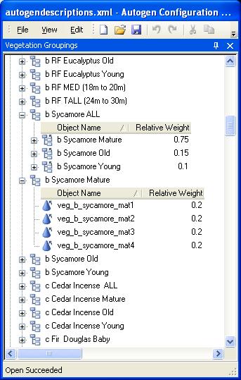
With the AutogenDescriptions.XML file open in the Autogen Configuration Editor, ensure the Vegetation Groupings and Model Entries windows are open. In the example below the grouping b Sycamore ALL refers to three other groupings (Mature, Old and Young). The relative weights are totaled (they need not total to any specific number) and the number of times a sub-grouping is chosen is calculated by dividing the relative weight by the total weight. For example, Sycamore Mature will be chosen for 75% of the vegetation areas referencing this grouping, Sycamore Old 15% of the areas, and Sycamore Young 10% of the areas. The Sycamore Mature grouping contains references to four models, each with an equal weight, so each model will be chosen for 25% of the vegetation areas.
A grouping can contain references to both other groupings and individual models. In all cases the relative weights determine how often a model, or group of models, is to be used. When creating vegetation areas using the Annotator tool, select any level of vegetation from the high level groupings to the particular model entries, and an appropriate selection of that vegetation will be rendered at run-time.
 |
.jpg) |
Tutorial: A Tree for All Seasons
Whereas evergreen trees can look quite similar regardless of the season of the year, deciduous trees can look quite different in each season: leafless and spindly in winter, a bloom of yellow and green in spring and summer, and a spectacular display of reds and browns in fall. In order to enable this variety in appearance, one type of tree can be represented using five different models -- one for each of the four seasons, plus "hard winter" when the tree is covered in snow. This differs from some previous versions of the simulator which attempted to programmatically add seasonal effects.
Note
The use of the AutogenDescriptions.XML file is the only system that supports different models for each season. Although it is supplied only with vegetation it could be used for other purposes -- such as adding rocks (with a variety of seasonal moss on them perhaps), ponds and other earthly features, or even signs of human activity such as tents (set with a very low RelativeWeight so that they appear infrequently).
The following tutorial shows the process of adding the hardy deciduous Birch tree to the vegetation for the land class definition of Cool Conifer Forest.
Step 1: Using 3ds Max create five Birch tree models
- Refer to step 1 of the previous tutorial: Adding a New Autogen Class, only this time create five tree models. Call the models BirchSpring, BirchSummer, BirchFall, BirchMildWinter, and BirchHardWinter. It is not necessary to create the thumbnail images used in the previous tutorial for the purposes of this tutorial, though they should be created if the tree models might be used as library objects.
- When you are satisfied with the models -- and have exported them correctly - copy the five .X files to the Environment Kit\Modeling SDK\3DSM7\Plugins folder.
Step 2: Create five .MDL files for the tree models
- Refer to step 2 of the previous tutorial, creating five .MDL files.
- Copy the five .MDL files to the Environment Kit\BGL Compiler SDK folder.
- Copy one of the sample placement XML files to the Environment Kit\BGL Compiler SDK folder, and rename it Birch.XML.
Step 3: Create a .BGL file containing references to the five models
Refer to step 3 of the previous tutorial. Edit the Birch.XML file so that it contains the following:
<?xml version="1.0" encoding="ISO-8859-1" ?>
- <FSData version="9.0" xmlns:xsi="http://www.w3.org/2001/XMLSchema-instance" xsi:noNamespaceSchemaLocation="bglcomp.xsd">
<ModelData sourceFile="BirchSpring.MDL" />
<ModelData sourceFile="BirchSummer.MDL" />
<ModelData sourceFile="BirchFall.MDL" />
<ModelData sourceFile="BirchMildWinter.MDL" />
<ModelData sourceFile="BirchHardWinter.MDL" />
</FSData>Drag the Birch.XML file onto the BGL Compiler, then copy the resulting Birch.BGL file to the Microsoft ESP\1.0\Addon Scenery\scenery folder. If your models include textures, move those textures to the Microsoft ESP\1.0\Addon Scenery\texture folder.
Step 4: Create a Birch Vegetation Grouping
- Open up the AutogenConfigEditor tool, and ensure the Model Entries window is open.
- Right click in the Model Entries window, and select Add. This will add a new model entry called "_New ModelEntry_". If a model or grouping entry starts with an underscore, it will appear at the top of the list of all entries, which can be helpful when editing properties.
- Change the FriendlyName to Birch (or _Birch), change the MaxScale to 1.1 and MinScale to 0.9 (or an appropriate range for random variation, the scaling is applied to all dimensions of the tree). Leave the IntersectionThreshold and ReferenceHeight as they are (these fields are not currently used).
- In the SeasonEntry collection, enter the five models with their GUIDs for the appropriate season. The GUID for each model can be found either in the .X file for each model (in the GuidtoName entry), or in the placement .XML file (in the LibraryObject entry). If one model is to be identical in two or more seasons, simply enter its GUID in the appropriate number of locations.
- In the Vegetation Groupings window right click and Add a grouping (say, called _BirchGroup), and then click on and drag the Birch entry from the Model Entries window over the top of the _BirchGroup grouping, and the mouse icon should change shape (to an arrow inside a box). Releasing the mouse button will now add the model entry to the grouping.
Step 5: Add the Vegetation Grouping to the Regionalization
- In the Vegetation Groupings window open up the Regionalizations entry, and scroll down to find Regionalization of Cool Conifer Forest. Open the Default entry. You should now see the single ag Forest Conifer entry.
- Open up a second view of the Vegetation Groupings window (using the New View entry in the right click menu).
- Drag and drop the _BirchGroup grouping entry over the Default entry for Regionalization of Cool Conifer Forest. You should now see the new group entry at the same height in the tree as ag Forest Conifer.
- Edit the properties of the new entry so that the _BirchGroup has a RelativeWeight of 100, and leave the entry for ag Forest Conifer unchanged. This is a way of ensuring that your new models will be highly visible, without altering the data for existing models. Obviously the weights can be edited later on to achieve the desired mix of vegetation.
Note
The grouping entries in the Vegetation Groupings section of the AutogenDescriptions.XML file that have names that start with "Terrain Autogen Class" (such as Terrain Autogen Class Dirt) are the defaults for the Autogen class, referenced by the Default entries in the Regionalizations.
Step 6: Save the AutogenDescriptions.XML file and run the simulation
- The AutogenDescriptions.XML file should be saved to the ESP\1.0\Autogen folder. However, as this folder contains a binary version of this file, AutogenDescriptions.SPB, then rename this binary version to something like AutogenDescriptions_saved.SPB.
- Run the simulation. To view the new trees easily take off from Yakima Air Term/Mcallister airport (KYKM) and head West. Thousands of your new trees should now be visible -- no need to change the Autogen Density settings for this.
- Change the season in the simulation to view the different models.
Step 7: Make the changes permanent
- When you are satisfied with the new models, go back into the AutogenDescriptions.XML file and apply the correct weights to the new groupings. If the Birch trees are to appear in all uses of the ag Forest Conifer grouping, then remove the BirchGroup from the Regionalization of Cool Conifer Forest entry, and instead add it to the ag Forest Conifer group.
- If the new tree models should also be included in an annotated Autogen texture, then follow the process in the previous tutorial: Adding a New Autogen Class. Note that if an Autogen texture is not annotated, then by default the whole area is assumed to be of the one default vegetation type. However if a texture is annotated, even with just one entry, then vegetation areas (usually polyline regions) will need to be defined for vegetation to appear.
- Refer to the section Creating an SPB File in the Creating XML Gauges document to convert the .XML file to a binary (and slightly more efficient) .SPB file.
Hints on Creating Tree Models
From a geometric point of view trees are very complex structures, and the modeling and rendering of them needs to be greatly simplified for performance reasons -- with thousands of trees in sight a complex model of a single tree, repeated thousands of times, is going to slow the rendering of the view to a crawl. Also, and for the same reason, trees are not animated -- they do not sway in the wind for example. The following image shows a high, medium and low complexity model of a fir tree.
.jpg)
The low complexity model is used almost exclusively by default throughout the simulation. It consists of two vertical cards (rectangular flat polygons) with images on both sides of the cards. The images used are not the same, so that when the trees are randomly rotated during placement, they look suitably different. The model also consists of two horizontal rectangles with an image only on the upper face, so that the model is more convincing when looking down on the tree. One method for creating these top down images is to render the high complexity model, view it top down, and capture the image.
The high complexity model consists of a 3D model of the trunk, and perhaps one or two major branches in a very large tree, with a range of cards with either branches on them, or clusters of foilage. The branch images can either appear on both sides of the card, or just on one side, depending on the height and angle of the card.
The medium complexity model is similar to the high complexity model, but with larger and few cards containing the branch images.
Models for the four seasons can be made from identical sets of cards, but with different textures applied. There is a range of third party products providing both images of trees that can be used by your own models, and model making tools that can construct tree models for input into 3ds Max.
If a large tree is a particular landmark in its own right, then placing a model with some complexity to it might be appropriate. However for the vast majority of trees, and all other vegetation, the simplest of the models is often the best to use.
Note: The current version of the simulation does not support multiple LOD models for scenery. If there are multiple LOD models, the highest LOD model is always used.
Autogen Validation Tools
There are a number of tools that can be used to validate various Autogen files. These tools are all command-line driven, and each has its own config file ( a file with the same name as the tool, but with .config appended to it) describing its default behavior. There are four levels of text output: verbose, information, warnings and errors. The output level is set in the config file. The tools are described in the following table.
| AC2Scan | Validates the default.XML file (found in the ESP\Autogen folder), checking for consistency with the regions and classes within the file, and that the GUIDs reference models that exist. |
| AC3Scan | Validates the AutogenDescriptions, Extrusions, Materials, RoofDescriptions and TerrainAutogenClassDescriptions files (either XML or SPB versions), primarily checking for the existence of models and textures. |
| AGNScan | Validates .AGN (Autogen annotation files) primarily checking that the GUIDs referred to exist in the appropriate configuration files. |
| ContentScan | This tool combines the three Autogen validation tools, along with the BGLScan and MDLScan tools. This tool does not take any inputs, all the settings it uses are in the ContentScan.exe.config file. |
Creating an SPB file
The AutogenDescriptions, Extrusions, Materials, RoofDescriptions and TerrainAutogenClassDescriptions files can either be in XML or SPB (Sim-Prop Binary) format. See the section Creating an SPB File in the Creating XML Gauges document for details on how to use the simpropcompiler tool.
.jpg)