Create a circular code anchor
The process of creating a circular code anchor involves four basic steps:
Use the Anchor wizard to select the circular code anchor method.
Print the anchor from the PDF file that the Anchor wizard creates.
Attach the anchor to a physical object in the real world.
Gaze at the anchor on HoloLens to anchor the guide.
Watch the following video, for an overview of how to create a circular code anchor in Dynamics 365 Guides.
Set up a circular code anchor
You can access the Anchor wizard from the Outline page. The Outline page automatically appears after you create or open a guide.
On the Outline page, select Set your anchor now.
On the Choose an anchor method page, select Select for the Circular Code anchor method.
In step 1 of the wizard, select Download circular code to create a PDF file that is named Guides-CircularCodeAnchor. This file includes the anchor that you will print in step 6.
On your computer, in Adobe Acrobat Reader, open the Guides-CircularCodeAnchor file.
Important
Dynamics 365 Guides supports one size of circular code anchor. To ensure the best possible alignment accuracy, it's important that you print the anchor at the specified size. If you use Adobe Acrobat Reader, you can set the specified size to get the best printing results.
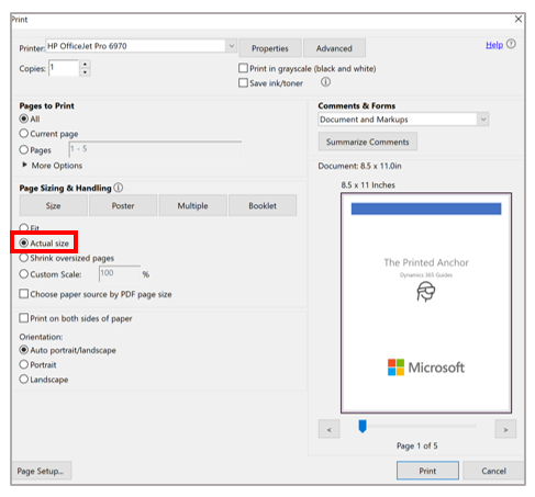
Select File > Print, and then, under Page Sizing & Handling, select the Actual size option.
Print the last page of the document on matte stock and don't laminate it. Glossy materials can affect scanning and will decrease the anchor detection rate. Bubble jet printers produce a better matte finish.
Note
Also, make sure the anchor is always positioned flat. Do not distort or place it on a curved surface as this will negatively affect alignment and detection.
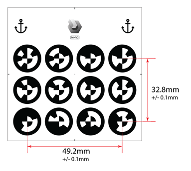
Make sure that the printed marker spacing matches the measurements shown in the following illustration as the size of the anchor can change depending on the printer used. The anchor measurements must be exact.
Note
If the anchor spacing isn't within +/– 0.1 mm, in the Print dialog box, select the Custom Scale option, and then change the percentage to compensate for the size discrepancy. For example, if the result is 49 mm when you print the anchor, change the scale to 100.4 percent to get 49.196 mm, which is within tolerance.
Attach the circular code anchor to a physical object in the real world, and then take a picture to help the operator find it.
Return to the Anchor wizard in the PC app, and then select Next two times. (You can skip step 2 of the wizard if you took a picture of the location in the previous step.)
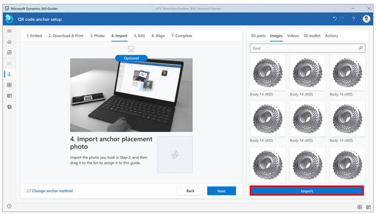
In step 3 of the wizard, select Import to import the picture that you took in step 8. Then drag it to the Import anchor placement photo box. When you've finished, select Next to move to the next step.
In step 4 of the wizard, if you want to change the default instructions for the operator, select Edit Step card text, and then enter your instructions. When you've finished, select Next to move to the next step.
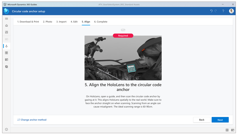
Put on your HoloLens, open your guide, and then gaze at the circular code anchor to anchor the guide.


Best practices for circular code anchors
Keep the following points in mind when you work with circular code anchors:
Material surface - Make sure to print the anchor on matte stock, and don't laminate it. Glossy materials can negatively affect scanning due to reflected light. Also, make sure that the anchor is flat. An anchor that is curved or distorted can affect alignment and detection.
Same anchor for authoring and printing - For best accuracy, use the same circular code anchor for authoring and operating.
Size - Make sure that your anchor is the exact size indicated in this article. Incorrect anchor size will cause guide misalignment.
Some applications and printers might change the size of the image.
If the anchor is larger than indicated, HoloLens interprets the scale difference in distance. Therefore, the anchor is identified as closer than it really is.
The best way to make sure that the anchor isn't resized is to print it from the PDF file, as described earlier in this article.
Location - Place the anchor in a location on the physical object that's easy to access and out of the way.
Ideally, anchor placement should be central to the steps being done.
Content placed farther away from the anchor will be less accurate.
Place the anchor where operators can quickly rescan to realign at any time.
Ideally, the anchor should not be moved after the author places it. If a permanent placement isn't possible, consider creating a mount so that the anchor can be consistently placed in the same location/orientation every time.
Take a photo or video to document the anchor placement, and add it to the guide instructions to help increase operator confidence. For information about how to capture a photo or video from HoloLens, see Create mixed reality photos and videos.
Scanning angle - Make sure you're facing the anchor straight on at the correct distance when gazing at it. Scanning from glancing angles can cause detection failure or misalignment. The ideal scanning range is from 60 to 80 cm.