Describe and implement RAS Gateway on Azure Stack HCI
A majority of customers that use financial services provided by your company require secure and reliable connections to their own datacenters. To accommodate this requirement, you’ve decided to explore the functionality provided by RAS Gateway.
Describe RAS Gateway
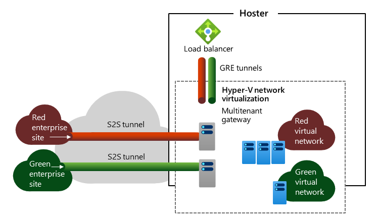
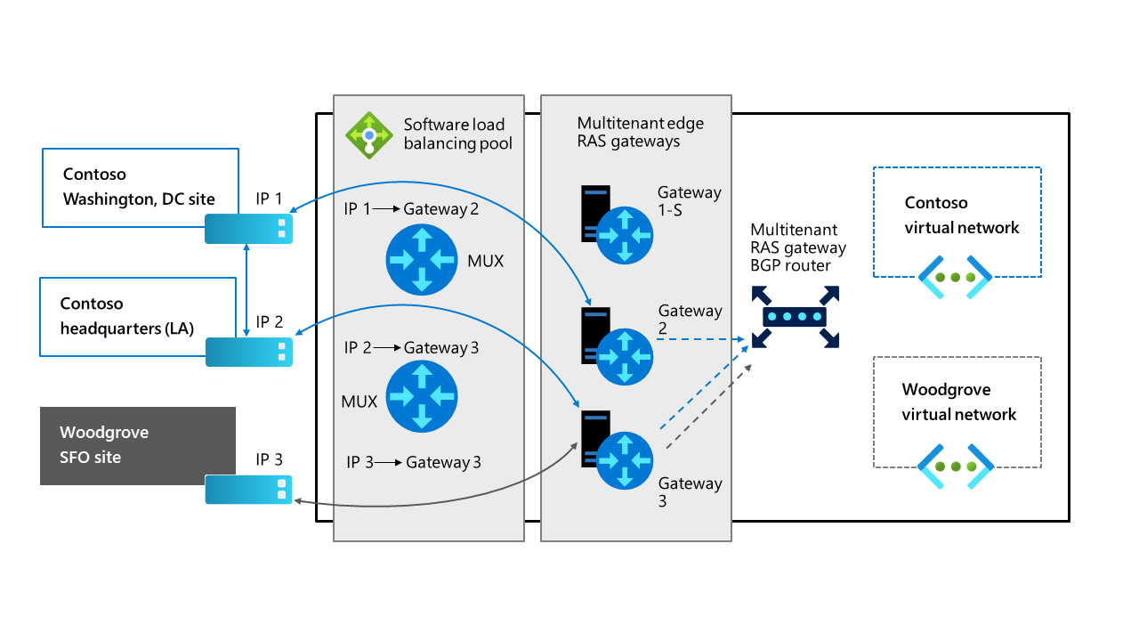
RAS Gateway is a software-based, BGP-capable router that’s based on Microsoft Hyper-V Network Virtualization and optimized for multitenancy scenarios. RAS Gateway implements routing between internal and external physical networks, and private and public clouds that support Internet Protocol security (IPsec) virtual private network (VPN) and GRE tunnels.
RAS Gateway offers support for the following core capabilities:
- Site-to-site (S2S) IPsec VPN
- S2S GRE Tunneling
- L3 Forwarding
- Dynamic routing with BGP
S2S IPsec VPN
This RAS Gateway capability provides virtual network connectivity across the internet by using an encrypted tunnel. In multitenant scenarios, tenants can access and manage their resources hosted on your Azure Stack HCI deployment from remote locations. The VPN functionality includes support for Internet Key Exchange v2 (IKEv2) and Point-to-Site (P2S) VPN.
S2S GRE Tunneling
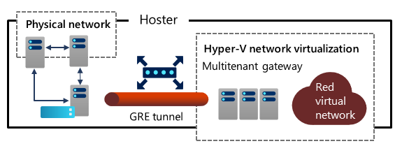
GRE is a lightweight tunneling protocol that can encapsulate a range of network layer protocols inside virtual point-to-point links over IP without the overhead of encryption. GRE tunneling facilitates implementation of the following scenarios:
- Access from the tenant's virtual networks to a physical network within the same hosting environment
- High-speed connectivity over a Multiprotocol Label Switching (MPLS) connection from the tenant's own on-premises network.
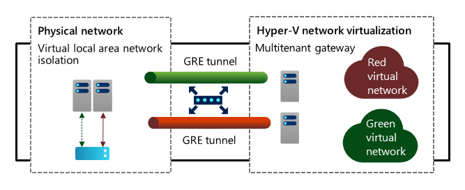
- Integration with VLAN-based isolation
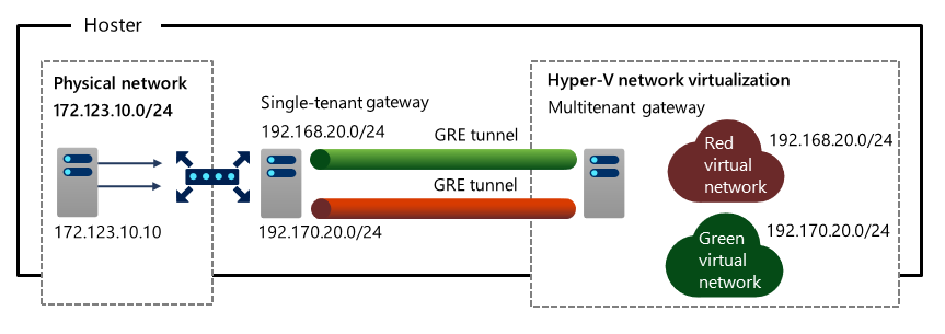
- Access from one or more tenants' virtual networks with non-overlapping IP address spaces to shared resources within a physical network of a hosting provider
L3 Forwarding
In this scenario, the gateway serves as a router between the Azure Stack HCI virtualized environment and the physical infrastructure in a datacenter. Each tenant uses its own VLAN-tagged logical network for the connectivity with the physical network.
Dynamic routing with BGP
As a dynamic routing protocol, BGP minimizes the need for manual route configuration on routers. When operating in a multisite environment connected by BGP-enabled routers such as RAS Gateway, BGP allows the routers to automatically learn routes and update their configuration to reflect to the existing network infrastructure; for example, as a result of setting up new connections or in response to network connectivity issues. With RAS Gateway in multitenant mode, BGP provides the ability to manage network traffic routing between tenants' VM networks and their remote sites.
Note
You can also use BGP for single-tenant RAS Gateway deployments, and when you use the Remote Access server role to implement a LAN router.
Routing information is advertised by RAS Gateway (and other SDN components such as Software Load Balancing Multiplexer) into the physical network using internal BGP peering. However, you’ll need to create a BGP peer on the router that your SDN infrastructure uses to receive routes for the networks advertised by the Software Load Balancing Multiplexer and RAS Gateway. BGP peering only needs to occur one way (from the Software Load Balancing Multiplexer or RAS Gateway to the external BGP peer).
Note
You must configure the BGP router peer to use its own ASN and allow peering from an ASN that’s assigned to the SDN components (Software Load Balancing Multiplexer and RAS Gateway).
Implement RAS Gateway and gateway connections
Before you create gateway connections and virtual tenant gateways, you have to implement SDN RAS Gateway. In addition, IPsec connections require that you implement SDN Software Load Balancers. The RAS Gateway infrastructure consists of gateway pools and BGP Route Reflector.
Describe gateway pools
Gateway pools are groups of SDN-managed VMs that route network traffic between physical and virtual networks. Pools have the following properties:
- Each pool is M+N redundant, which means that M active gateway VMs are backed up by N standby gateway VMs. M+N redundancy provides extra flexibility when implementing highly available RAS Gateway deployments.
- A pool can perform any combination of individual gateway functions, such as S2S, L3, and GRE.
- In a multitenant RAS Gateway deployment, the gateway pools are deployed behind an SDN SLB, which allows you to assign a single public IP address for the entire deployment.
- You can scale pools horizontally by adding or removing gateway VMs. Removing or adding gateways doesn’t disrupt the services that are provided by a pool.
- You can define pools based on a number of criteria, including:
- Connection types, such as S2S, L3, or GRE
- Capacity
- Redundancy level
- Tenant separation
For example, you can create a gateway pool that supports both high throughput and low throughput IKEv2 S2S connections, or one that’s available to a designated tenant only.
Note
You can add tenant virtual gateways to gateway pools. Network Controller automatically determines the most suitable RAS Gateway VM to use when you deploy a new virtual gateway.
Implement gateway pools
All Azure Stack HCI SDN RAS Gateway VMs reside in the gateway pool named DefaultAll. To create additional gateway pools and allocate RAS Gateway VMs to them, you can use the 'New-NetworkControllerGatewayPool' PowerShell cmdlet.
Implement and manage gateway connections
Windows Admin Center facilitates provisioning and management of gateway connections, including IPSec, GRE, and L3 connections.
Create an IPsec gateway connection
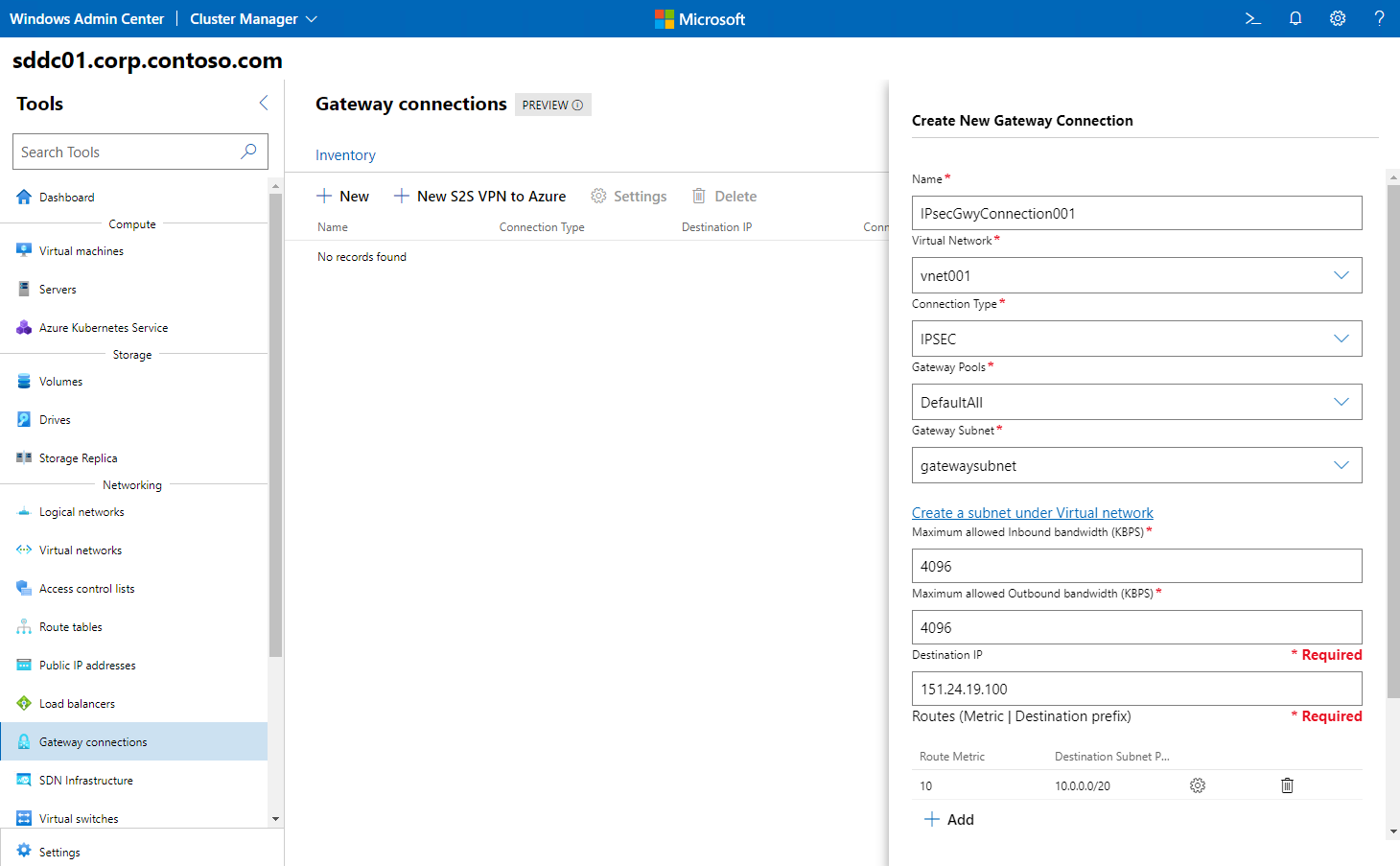
Creating an IPsec gateway connection by using Windows Admin Center involves the following sequence of steps:
- In Windows Admin Center, connect to the Azure Stack HCI cluster.
- In the Tools pane, in the Networking section, select Gateway Connections.
- On the Gateway Connections page, select the Inventory tab, and then select New.
- In the Create a new Gateway Connection pane, perform the following tasks:
- In the Name box, enter a name for the connection.
- In the Virtual networks drop-down list, select the virtual network for which the gateway will provide connectivity.
- In the Connection Type drop-down list, select IPSEC.
- In the Gateway Pools drop-down list, select the target RAS Gateway pool.
- In the Gateway Subnet drop-down list, select the dedicated subnet of the virtual network that will host the gateway connection.
- In the Maximum allowed Inbound bandwidth (KBPS) box, provide a value representing the total capacity of the gateway that you select during its provisioning.
- In the Maximum allowed Outbound bandwidth (KBPS) box, provide a value representing the total capacity of the gateway that you select during its provisioning.
- In the Destination IP box, enter the IP address of the remote gateway.
- Add Routes to the connection, including their respective metrics and destination subnet prefixes.
- Enter the IPsec shared secret that matches the secret configured on the remote gateway, then select Create.
Create a GRE gateway connection
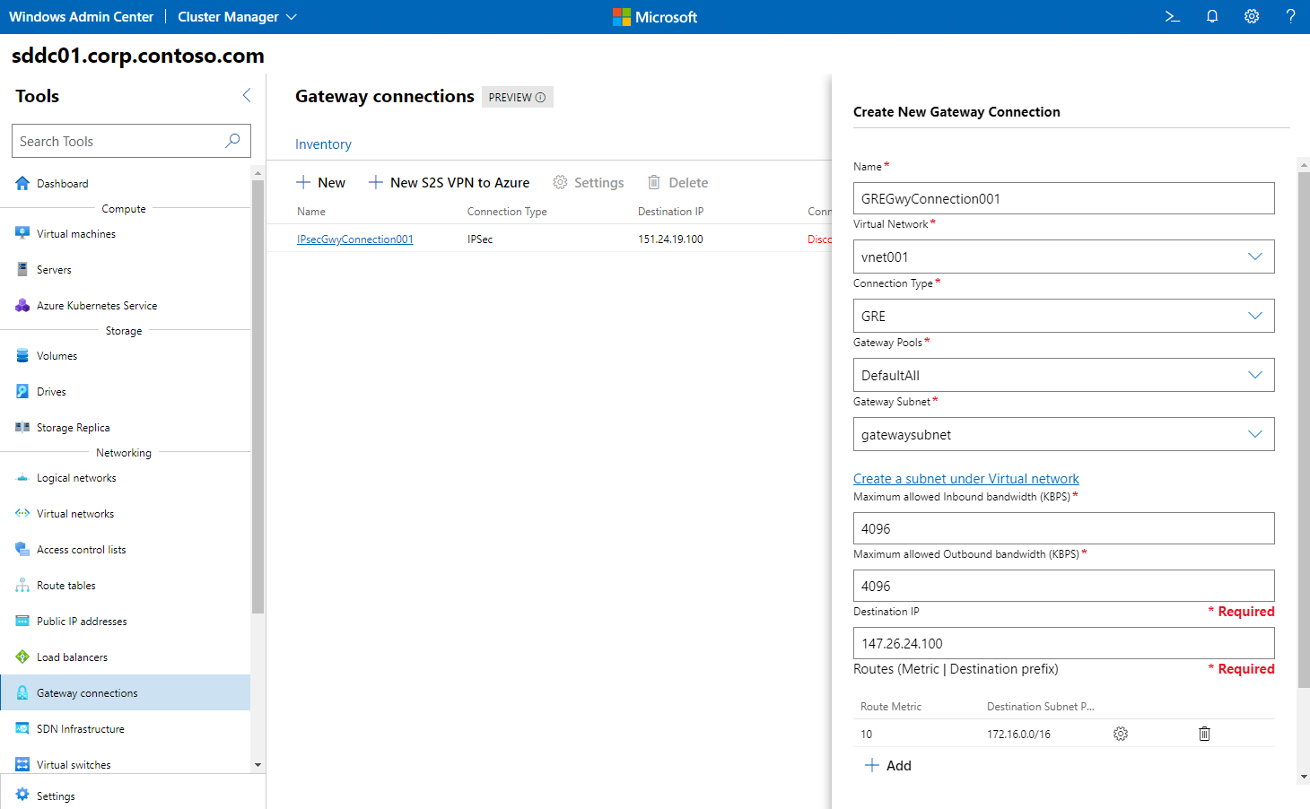
For the most part, creating a GRE gateway connection by using Windows Admin Center involves the same sequence of steps as creating an IPsec gateway connection. The primary distinction is that in the Connection Type drop-down list, you select the GRE option instead, and then use the GRE key that matches the key configured on the remote gateway (rather than the IPsec shared secret).
Create an L3 gateway connection
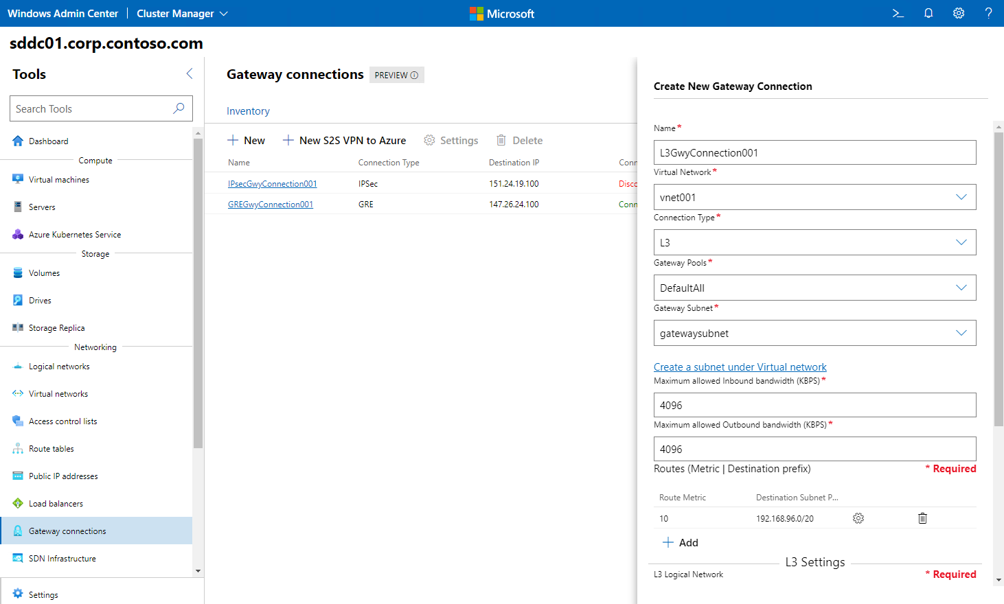
The process of creating an L3 gateway connection by using Windows Admin Center also doesn’t differ significantly from the previous two procedures. However, in addition to selecting the L3 option in the Connection Type drop-down list, you must specify additional settings, including:
- A network for the L3 Logical Network. This represents the physical network that requires connectivity to the virtual network. You need to create this network first as an SDN logical network.
- An L3 Logical Subnet in the L3 Logical Network. You need to assign a VLAN ID to this subnet.
- An IP address in the CIDR format corresponding to the L3 IP Address/Subnet Mask. This IP address is configured on the gateway interface.
- An L3 Peer IP address on the L3 Logical Subnet that will serve as the next hop on the physical network after traffic originating from the virtual network reaches the gateway.
Modify and delete gateway connections
You can change a number of connection settings for IPsec, GRE, and L3 connections. These settings include:
- For IPsec connections:
- The maximum allowed inbound and outbound bandwidth
- The destination IP address
- Destination prefix and route metric
- IPsec preshared key
- For GRE connections:
- The maximum allowed inbound and outbound bandwidth
- The destination IP address, destination prefix and route metric
- The GRE key
- For L3 connections:
- The maximum allowed inbound bandwidth and outbound bandwidth, destination prefix and route metric
- The L3 Logical Network, L3 Logical Subnet, L3 IP Address, and the L3 Peer IP
Windows Admin Center also allows you to delete any of the gateway connections you created. You can do this from the Inventory tab on the Gateway Connections page.
