Note
Access to this page requires authorization. You can try signing in or changing directories.
Access to this page requires authorization. You can try changing directories.
The Image Editor in Visual Studio is a tool that you can use to view and modify texture and image resources. Specifically, you can use the Image Editor to work with the kinds of rich texture and image formats that are used in DirectX app development. Image Editor includes support for popular image file formats and color encodings, features such as alpha-channels and MIP-mapping, and many of the highly compressed, hardware-accelerated texture formats that DirectX supports.
Supported formats
The Image Editor supports the following image formats:
| Format name | File Name Extension |
|---|---|
| Portable Network Graphics | .png |
| JPEG | .jpg, .jpeg, .jpe, .jfif |
| Direct Draw Surface | .dds |
| Graphics Interchange Format | .gif |
| Bitmap | .bmp, .dib |
| Tagged Image File Format | .tif, .tiff |
| TGA (Targa) | .tga |
Get started
This section describes how to add an image to your Visual Studio project and configure it for your requirements.
Add an image to your project
In Solution Explorer, open the shortcut menu for the project that you want to add the image to, and then choose Add > New Item.
In the Add New Item dialog box, under Installed, select Graphics, and then select an appropriate file format for the image.
Note
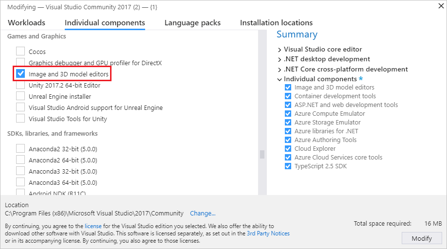
If you don't see the Graphics category in the Add New Item dialog, you may need to install the Image and 3D model editors component. Close the dialog and then select Tools > Get Tools and Features from the menu bar, to open the Visual Studio Installer. Select the Individual components tab, and then select the Image and 3D model editors component under the Games and Graphics category. Select Modify.
For information about how to choose a file format based on your requirements, see Choose the image format.
Specify the Name of the image file and the Location where you want it to be created.
Choose the Add button.
Choose the image format
Depending on how you plan to use the image, certain file formats might be more appropriate than others. For example, some formats might not support a feature that you need, for example, transparency or a specific color format. Some formats might not provide suitable compression for the kind of image content you have planned.
The following information can help you choose an image format that meets your needs:
Bitmap Image (.bmp)
The bitmap image format. An uncompressed image format that supports 24-bit color. The bitmap format doesn't support transparency.
GIF Image (.gif)
The Graphics Interchange Format (GIF) image format. An LZW-compressed, lossless image format that supports up to 256 colors. Unsuitable for photographs and images that have a significant amount of color detail, but provides good compression ratios for low-color images that have a high degree of color coherence.
JPG Image (.jpg)
The Joint Photographic Experts Group (JPEG) image format. A highly compressed, lossy image format that supports 24-bit color and is suitable for general-purpose compression of images that have a high degree of color coherence.
PNG Image (.png)
The Portable Network Graphics (PNG) image format. A moderately compressed, lossless image format that supports 24-bit color and alpha transparency. It's suitable for both natural and artificial images, but doesn't provide compression ratios as good as lossy formats such as JPG or GIF.
TIFF Image (.tif)
The Tagged Image File Format (TIFF or TIF) image format. A flexible image format that supports several compression schemes.
DDS Texture (.dds)
The DirectDraw Surface (DDS) texture format. A highly compressed, lossy texture format that supports 24-bit color and alpha transparency. Its compression ratios can be as high as 8:1. It's based on S3 Texture compression, which can be decompressed on graphics hardware.
TGA Image (.tga)
The Truevision Graphics Adapter (TGA) image format (also known as Targa). An RLE-compressed, lossless image format that supports both color-mapped (color palette) or direct-color images of up to 24-bit color and alpha transparency. Unsuitable for photographs and images that have a significant amount of color detail, but provides good compression ratios for images that have long spans of identical colors.
Configure the image
Before you begin to work with the image that you created, you can change its default configuration. For example, you can change its dimensions or the color format that it uses. For information about how to configure these and other properties of the image, see Image properties.
Note
Before you save your work, make sure to set the Color Format property if you want to use a specific color format. If the file format supports compression, you can adjust the compression settings when you save the file for the first time or when you choose Save As.
Work with the Image Editor to modify textures and images
Commands that affect the state of the Image Editor are located on the Image Editor Mode toolbar together with advanced commands. The toolbar is located along the topmost edge of the Image Editor design surface. Drawing tools are located on the Image Editor toolbar along the leftmost edge of the Image Editor design surface.
Image Editor Mode toolbar

The following table describes the items on the Image Editor Mode toolbar, which are listed in the order in which they appear from left to right:
| Toolbar Item | Description |
|---|---|
| Select | Enables selection of a rectangular region of an image. After you select a region, you can cut, copy, move, scale, rotate, flip, or delete it. When there's an active selection, drawing tools only affect the selected region. |
| Irregular Selection | Enables selection of an irregular region of an image. After you select a region, you can cut, copy, move, scale, rotate, flip, or delete it. When there's an active selection, drawing tools only affect the selected region. |
| Wand Selection | Enables selection of a similarly colored region of an image. The tolerance—that is, the maximum difference between adjacent colors within which they're considered similar—can be configured to include a smaller or wider range of similar colors. After you select a region, you can cut, copy, move, scale, rotate, flip, or delete it. When there's an active selection, drawing tools only affect the selected region. |
| Pan | Enables movement of the image relative to the window frame. In Pan mode, select a point on the image and then move it around. You can temporarily activate Pan mode by pressing and holding the Ctrl key. |
| Zoom | Enables the display of more or less image detail relative to the window frame. In Zoom mode, select a point on the image and then move it right or down to zoom in, or left or up to zoom out. You can zoom in or out by pressing and holding Ctrl while you either use the mouse wheel or press the plus sign (+) or minus sign (-). |
| Zoom to Actual Size | Displays the image by using a 1:1 relationship between the pixels of the image and the pixels of the screen. |
| Zoom To Fit | Displays the full image in the window frame. |
| Zoom To Width | Displays the full width of the image in the window frame. |
| Grid | Enables or disables the grid that shows pixel boundaries. The grid might not appear until you zoom into the image. |
| View Next MIP Level | Activates the next larger MIP level in a MIP map chain. The active MIP level is displayed on the design surface. This item is only available for textures that have MIP levels. |
| View Previous MIP Level | Activates the next smaller MIP level in a MIP map chain. The active MIP level is displayed on the design surface. This item is only available for textures that have MIP levels. |
| Red Channel Green Channel Blue Channel Alpha Channel |
Enables or disables the specific color channel. Note: By systematically enabling or disabling color channels, you can isolate problems that are related to one or more of them. For example, you could identify incorrect alpha transparency. |
| Background | Enables or disables display of the background through transparent parts of the image. You can configure how the background is displayed by choosing from these options: Checkerboard Uses a green color together with the specified background color to display the background as a checkerboard pattern. You can use this option to help make transparent parts of the image more apparent. White Background Uses the color white to display the background. Black Background Uses the color black to display the background. Animate Background Pans the checkerboard pattern slowly. You can use this option to help make transparent parts of the image more apparent. |
| Properties | Alternately opens or closes the Properties window. |
| Advanced | Contains additional commands and options. Filters Provides several common image filters: Black and White, Blur, Brighten, Darken, Edge Detection, Emboss, Invert Colors, Ripple, Sepia Tone, and Sharpen. Graphics Engines Render with D3D11 Uses Direct3D 11 to render the Image Editor design surface. Render with D3D11WARP Uses Direct3D 11 Windows Advanced Rasterization Platform (WARP) to render the Image Editor design surface. Tools Flip Horizontal Transposes the image around its horizontal, or x, axis. Flip Vertical Transposes the image around its vertical, or y, axis. Generate Mips Generates MIP levels for an image. If MIP levels already exist, they're recreated from the largest MIP level. Any changes that were made to smaller MIP levels are lost. To save the MIP levels that you have generated, you must use the .dds format to save the image. View Frame Rate When enabled, displays the frame rate in the upper-right corner of the design surface. The frame rate is the number of frames that are drawn per second. Tip: You can choose the Advanced button to run the last command again. |
Image Editor toolbar

The following table describes the items on the Image Editor toolbar, which are listed in the order in which they appear from top to bottom:
| Toolbar Item | Description |
|---|---|
| Pencil | Uses the active color selection to draw an aliased stroke. You can set the color and thickness of the stroke in the Properties window. |
| Brush | Uses the active color selection to draw an anti-aliased stroke. You can set the color and thickness of the stroke in the Properties window. |
| Airbrush | Uses the active color selection to draw an anti-aliased stroke that blends together with the image and becomes more saturated as a function of time. You can set the color and thickness of the stroke in the Properties window. |
| Eyedropper | Sets the active color selection to the color of the selected pixel. |
| Fill | Uses the active color selection to fill a region of the image. The affected region is defined as the pixel where the fill is applied, together with every pixel that is connected to it by pixels of the same color and that is the same color itself. If the fill is applied within an active selection, then the affected region is constrained by the selection. By default, the active color selection is blended together with the affected region of the image according to its alpha component. To use the active color selection to overwrite the affected region, press and hold the Shift key when you use the fill tool. |
| Eraser | Sets pixels to the fully transparent color if the image supports an alpha channel. Otherwise, Eraser sets the pixels to the active background color. |
| Line, Rectangle, Rounded Rectangle, Ellipse | Draws a shape on the image. You can set the color and thickness of the outline in the Properties window. To draw a primitive that has equal width and height, press and hold Shift as you draw. |
| Text | Uses the foreground color selection to draw text. The background color is determined by the background color selection. For a transparent background, the alpha value of the background color selection must be 0. While the text region is active, you can set whether the text is drawn with an anti-aliased stroke, and you can set the text Value, Font, Size, and style—Bold, Italics, or Underlined—in the Properties window. The content and appearance of the text is finalized when the text region is no longer active. |
| Rotate | Rotates the image 90 degrees clockwise. |
| Trim | Trims the image to the active selection. |
Work with MIP levels
Some image formats, for example, DirectDraw Surface (.dds), support MIP levels for texture-space Level-of-Detail (LOD).
Work with transparency
Some image formats, for example, DirectDraw Surface (.dds), support transparency. There are several ways you can use transparency, depending on the tool that you're using. To specify the level of transparency for a color selection, in the Properties window, set the A (alpha) component of the color selection.
The following table describes how different kinds of tools control how transparency is applied:
| Tool | Description |
|---|---|
| Pencil, Brush, Airbrush, Line, Rectangle, Rounded Rectangle, Ellipse, Text | To blend the active color selection together with the image, in the Properties window, expand the Channels property group and set the Draw checkbox on the Alpha channel, and then draw normally. To draw by using the active color selection and leave the alpha value of the image in place, clear the Draw checkbox of the Alpha channel, and then draw normally. |
| Fill | To blend the active color selection together with the image, just choose the area to fill. To use the active color selection—including the value of the alpha channel—to overwrite the image, press and hold Shift and then choose the area to fill. |
Image properties
You can use the Properties window to specify various properties of the image. For example, you can set the width and height properties to resize the image.
The following table describes image properties:
| Property | Description |
|---|---|
| Width | The width of the image. |
| Height | The height of the image. |
| Bits Per Pixel | The number of bits that represent each pixel. The value of this property depends on the Color Format of the image. |
| Transparent Selection | True to blend the selection layer together with the main image, based on the alpha value of the selection layer; otherwise, False. This item is only available for images that support alpha. |
| Format | The color format of the image. You can specify various color formats, depending on the image format. The color format defines the number and kind of color channels that are included in the image, and also the size and encoding of various channels. |
| Mip Level | The active MIP level. This item is only available for textures that have MIP levels. |
| Mip Level Count | The total number of MIP levels in the image. This item is only available for textures that have MIP levels. |
| Frame Count | The total number of frames in the image. This item is only available for images that support texture arrays. |
| Frame | The current frame. Only the first frame can be viewed; all other frames are lost when the image is saved. |
| Depth Slice Count | The total number of depth slices in the image. This item is only available for images that support volume textures. |
| Depth Slice | The current depth slice. Only the first slice can be viewed; all other slices are lost when you save the image. |
Note
Because the Rotate by property applies to all tools and selected regions, it always appears at the bottom of the Properties window together with other tool properties. Rotate by is always displayed because the whole image is implicitly selected when there is no other selection or active tool. For more information about the Rotate by property, see Tool properties.
Resize images
There are two ways to resize an image. In both cases, the Image Editor uses bilinear interpolation to resample the image.
In the Properties window, specify new values for the Width and Height properties.
Select the entire image and use the border markers to resize the image.
Selected regions
Selections in the Image Editor define regions of the image that are active. Active regions are affected by tools and transformations. When there's an active selection, areas outside the selected region aren't affected by most tools and transformations. If there isn't an active selection, the entire image is active.
Most tools (Pencil, Brush, Airbrush, Fill, Eraser, and 2D primitives) and transformations (Rotate, Trim, Invert Colors, Flip Horizontal, and Flip Vertical) are constrained or defined by the active selection. However, some tools (Eyedropper and Text) and transformations (Generate Mips) aren't affected by any active selection. These tools always behave as if the entire image is the active selection.
While you're selecting a region, you can press and hold Shift to make a proportional (square) selection. Otherwise, the selection isn't constrained.
Resize selections
After you select a region, you can resize it or its image contents by changing the size of the selection marker. While you're resizing the selected region, you can use the following modifier keys to change the behavior of the selected region as you resize it:
Ctrl - Copies the contents of the selected region before it's resized. This leaves the original image intact while the copy is resized.
Shift - Resizes the selected region in proportion to its original size.
Alt - Changes the size of the selection region. This leaves the image unmodified.
The following table describes the valid modifier key combinations:
| Ctrl | Shift | Alt | Description |
|---|---|---|---|
| Resizes the content of the selected region. | |||
| Shift | Proportionally resizes the content of the selected region. | ||
| Alt | Resizes the selected region. This defines a new selection region. | ||
| Shift | Alt | Proportionally resizes the selected region. This defines a new selection region. | |
| Ctrl | Copies and then resizes the content of the selected region. | ||
| Ctrl | Shift | Copies and then proportionally resizes the content of the selected region. |
Tool properties
While a tool is selected, you can use the Properties window to specify details about how it affects the image. For example, you can set the thickness of the Pencil tool or the color of the Brush tool.
You can set both a foreground color and a background color. Both support an alpha channel to provide user-defined opacity. The settings apply to all tools. If you use a mouse, the left mouse button corresponds to the foreground color, and the right mouse button corresponds to the background color.
The following table describes tool properties:
| Tool | Properties |
|---|---|
| All tools and selections | Rotate by Defines the amount, in degrees, that the selection or tool effect is rotated in the clockwise direction. |
| Pencil, Brush, Airbrush, Eraser | Thickness Defines the size of the area that is affected by the tool. |
| Text | Anti-alias Draws text that has anti-aliased edges. This gives text a smoother appearance. Value The text to be drawn. Font The font used to draw the text. Size The size of the text. Bold Makes the font bold. Italics Makes the font italic. Underlined Makes the font underlined. |
| 2D Primitive | Anti-alias Draws primitives that have anti-aliased edges. This gives them a smoother appearance. Thickness Defines the thickness of the line that forms the boundary of the primitive. Radius X (Rounded rectangle only) Defines the rounding radius for the top and bottom edges of the primitive. Radius Y (Rounded rectangle only) Defines the rounding radius for the left and right edges of the primitive. |
| Pencil, Brush, Airbrush, 2D Primitive | Channels Enables or disables specific color channels for viewing and drawing. If View is set for a specific color channel, that channel is visible in the image; otherwise, it isn't visible. If Draw is set for a specific color channel, that channel is affected by drawing operations; otherwise, it isn't. |
| Wand Selection, Fill | Tolerance Defines the maximum difference between adjacent colors within which they're considered similar, so that fewer or more similar colors are made a part of the affected or selected region. By default, the value is 32, which means that adjacent pixels within 32 shades (lighter or darker) of the original color are considered to be part of the region. |
Keyboard shortcuts
| Command | Keyboard shortcuts |
|---|---|
| Switch to Select mode | S |
| Switch to Zoom mode | Z |
| Switch to Pan mode | K |
| Select all | Ctrl+A |
| Delete the current selection | Delete |
| Cancel the current selection | Esc (escape) |
| Zoom in | Ctrl+Mouse wheel forward Ctrl+PageUp Plus Sign (+) |
| Zoom out | Ctrl-Mouse wheel backward Ctrl-PageDown Minus Sign (-) |
| Pan the image up | Mouse wheel backward PageDown |
| Pan the image down | Mouse wheel forward PageUp |
| Pan the image left | Shift+Mouse wheel backward Mouse wheel left Shift+PageDown |
| Pan the image right | Shift+Mouse wheel forward Mouse wheel right Shift+PageUp |
| Zoom to actual size | Ctrl+0 (zero) |
| Fit image to window | Ctrl+G, Ctrl+F |
| Fit image to window width | Ctrl+G, Ctrl+I |
| Toggle grid | Ctrl+G, Ctrl+G |
| Crop image to current selection | Ctrl+G, Ctrl+C |
| View next (higher detail) MIP level | Ctrl+G, Ctrl+6 |
| View previous (lower detail) MIP level | Ctrl+G, Ctrl+7 |
| Toggle red color channel | Ctrl+G, Ctrl+1 |
| Toggle green color channel | Ctrl+G, Ctrl+2 |
| Toggle blue color channel | Ctrl+G, Ctrl+3 |
| Toggle alpha (transparency) channel | Ctrl+G, Ctrl+4 |
| Toggle alpha checkerboard pattern | Ctrl+G, Ctrl+B |
| Switch to irregular selection tool | L |
| Switch to wand selection tool | M |
| Switch to pencil tool | P |
| Switch to brush tool | B |
| Switch to fill tool | F |
| Switch to eraser tool | E |
| Switch to text tool | T |
| Switch to color-select (eyedropper) tool | I |
| Move the active selection, and its contents. | Arrow keys. |
| Resize the active selection, and its contents. | Ctrl+Arrow keys |
| Move the active selection, but not its contents. | Shift+Arrow keys |
| Resize the active selection, but not its contents. | Shift+Ctrl+Arrow keys |
| Commit the current layer | Return |
| Decrease tool thickness | [ |
| Increase tool thickness | ] |
Image Editor examples
The examples in this section show you how to use the Image Editor to create a basic texture and how to generate and modify MIP levels.
Create a basic texture
You can use the Image Editor to create and modify images and textures for your game or app. For example, you can set the size of the texture, set the foreground and background colors, use the alpha channel (transparency), use the Fill and Ellipse tools, and set tool properties.
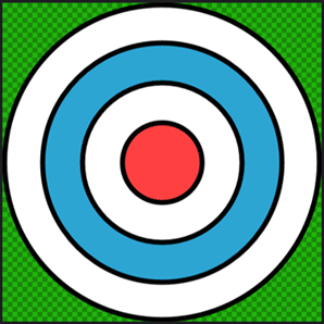
In this example, the following steps show you how to create a texture that represents a "bullseye" target. When you're finished, the texture should look like the following image. To better demonstrate the transparency in the texture, the Image Editor was configured to use a green, checkered pattern to display it.
Before you begin, make sure that the Properties window is displayed. You use the Properties window to set the image size, change tool properties, and specify colors while you work.
Create a "bullseye" target texture
Create a texture with which to work. For information about how to add a texture to your project, see Image Editor.
Set the image size to 512x512 pixels. In the Properties window, set the values of the Width and Height properties to
512.On the Image Editor toolbar, choose the Fill tool. The Properties window now displays the properties of the Fill tool together with the image properties.
Set the foreground color to fully transparent black. In the Properties window, in the Colors property group, select Foreground. Set the values of the R, G, B, and A properties next to the color picker to
0.On the Image Editor toolbar, choose the Fill tool, and then press and hold the Shift key and choose any point in the image. Using the Shift key causes the alpha value of the fill color to replace the color in the image; otherwise, the alpha value is used to blend the fill color together with the color in the image.
Important
This step, together with the color selection in the previous step, ensures that the base image is prepared for the "bullseye" target texture that you will draw. When the image is filled with transparent black—and because the border of the target is black—there will be no aliasing artifacts around the target.
On the Image Editor toolbar, choose the Ellipse tool.
Set the foreground color to fully opaque black. Set the values of the R, G, and B properties to
0and the value of the A property to255.Set the background color to fully opaque white. In the Properties window, in the Colors property group, select Background. Set the values of the R, G, B, and A properties to
255.Set the width of the outline of the ellipse. In the Properties window, in the Appearance property group, set the value of the Width property to
8.Make sure that anti-aliasing is enabled. In the Properties window, in the Appearance property group, make sure that the Anti-alias property is set.
Using the Ellipse tool, draw a circle from pixel coordinate
(3, 3)to pixel coordinate(508, 508). To draw the circle more easily, you can press and hold the Shift key while you draw.Note
The pixel coordinates of the current pointer location are displayed on the Visual Studio status bar.
Change the background color. Set R to
44, G to165, B to211, and A to255.Draw another circle from pixel coordinate
(64, 64)to pixel coordinate(448, 448).Change the background color back to fully opaque white. Set R, G, B, and A to
255.Draw another circle from pixel coordinate
(128, 128)to pixel coordinate(384, 384).Change the background color. Set R to
255, G and B to64, and A to255.Draw another circle from pixel coordinate
(192, 192)to pixel coordinate(320, 320).
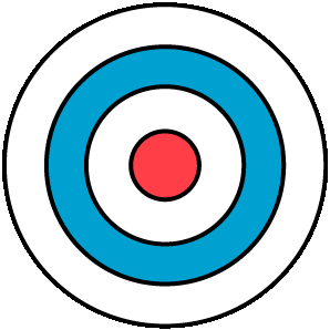
The "bullseye" target texture is complete. Here's the final image, shown with transparency.
To follow up, you can generate MIP levels for this texture. For information on how to do so, see the next section.
Create and modify MIP levels
This document demonstrates how to use the Image Editor to generate and modify MIP levels for texture-space Level-of-Detail (LoD).
Generating MIP levels
Mipmapping is a technique that's used to increase rendering speed and reduce aliasing artifacts on textured objects by precalculating and storing several copies of a texture in different sizes. Each copy, which is known as a MIP level, is half the width and height of the previous copy. When a texture is rendered on the surface of an object, the MIP level that corresponds most closely to the screen-space area of the textured surface is automatically chosen. This means that the graphics hardware doesn't have to filter oversized textures to maintain consistent visual quality. Although the memory cost of storing the MIP levels is about 33 percent more than that of the original texture alone, the performance and image-quality gains justify it.
To generate MIP levels
Begin with a basic texture. For best results, specify a texture that has a width and height that are a power of two in size, for example, 256, 512, 1024, and so on.
Generate the MIP levels. On the Image Editor Mode toolbar, choose Advanced > Tools > Generate Mips.
Notice that the Go to Next Mip Level and Go to Previous Mip Level buttons now appear on the Image Editor Mode toolbar. If the Properties window is displayed, also notice that the read-only properties Mip Level and Mip Level Count now appear in the image properties.
Modifying MIP levels
To achieve special effects or increase image quality at specific levels of detail, you can modify each MIP level individually. For example, you can give a textured object a different appearance at a distance (greater distance corresponds to smaller MIP levels), or you can ensure that textures that contain text or symbols remain legible even at smaller MIP levels.
To modify an individual MIP level
Select the MIP level that you want to modify. On the Image Editor Mode toolbar, use the Go to Next MIP Level and Go to Previous MIP Level buttons to move between MIP levels.
After you select the MIP level that you want to modify, you can use the drawing tools to modify it without changing the contents of other MIP levels. The drawing tools are available on the Image Editor toolbar. After you select a tool, you can change its properties in the Properties window.
Note
If you do not need to modify the contents of individual MIP levels—as you might do to achieve certain effects—we recommend that you generate mipmaps from the source texture at build time. This helps to ensure that MIP levels stay in sync with the source texture because modifications to a MIP level are not propagated to other levels automatically.
Related content
Visit the Export textures page to learn how to use the Image Content Pipeline to export textures that contain mipmaps, premultiplies alpha, and more.