Note
Access to this page requires authorization. You can try signing in or changing directories.
Access to this page requires authorization. You can try changing directories.
This document provides recommendations for the design and development of devices with integrated ambient light sensors. Selecting a suitable ambient light sensor (ALS) device is critical.
The following high-level checklist is for developers integrating sensor hardware into devices. The rest of this document describes the process and background information in detail.
- Select a suitable backlight source.
- Select a suitable light sensor.
- Select optimized placement for the light sensor in the device enclosure.
- Perform per-model calibration taking into account all factors, such as coatings, light pipe, sensor configuration, placement, and so on. This should be performed using professional, pre-calibrated light meters.
- Integrate the sensors on to the device in one of the supported ways.
- Leverage the inbox HID Sensor class driver. Connect the device over USB, SPI, or I2C HID transport.
- Test the complete device as a light measurement instrument. Use various types of test lighting (incandescent, fluorescent, LED) at various intensities and compare values reported through the sensor platform with a high-quality light meter. The meter should measure light incident on the display of the device.
- Test the device and third-party drivers with the Windows Hardware Lab Kit (HLK) device requirements and related tests. Ensure that it runs correctly and passes all test cases.
- Ensure that OEMs, ODMs, and IHVs participate in mechanical design reviews for each major revision of device hardware.
- Ensure that sensor implementation is optimized mechanically, optically, and from an electrical engineering perspective.
- Test light sensors and adaptive brightness using the steps mentioned in Adaptive brightness test cases.
Integrating light sensors with device hardware
Several things can greatly affect what can be done with the information that the light sensors provide. These considerations include the following:
- The type of sensor, digital light sensors are preferred
- The accuracy, resolution, and field of view of the sensor
- The dynamic range of the sensor
- Infrared (IR) and ultraviolet (UV) rejection (human eye response)
- The supported bus technology (digital only)
- The digital sampling rate
- Power consumption
- Packaging and placement options
The following factors warrant special consideration:
- Accuracy and resolution: To deliver an optimal user experience for adaptive brightness and light-aware UI in applications, accurate sensor data is required as input. Generally, the more accurate the sensor, the better the corresponding user experience will be. A good goal for actual ambient light sensor (ALS) calibrated values is a consistent accuracy of within 4 percent of actual lighting conditions.
- Dynamic range: The dynamic range of a light sensor is the ratio between the largest and smallest values that the sensor can report, and defines range of lighting environments in which the sensor can be effective. A low dynamic range light sensor limits the environments in which it can be used. The ambient light sensors mounted on devices designed to be used outdoors, such as a cell phone, should support outdoor lighting conditions. Sunlight can range from 0 to 10,000 lux, or more. The ALS dynamic range for devices designed to be used indoors can be smaller. Indoor light typically ranges from 0 to 1000 lux.
- Granularity: To ensure the best experience the ALS should have a granularity of 1 lux when the ambient light is below 25 lux, and a granularity of 4% of the ambient light when it is above 25 lux. This enables the adaptive brightness algorithm to perform smooth screen brightness transitions.
The following are common lighting conditions to reference:
| Lighting condition | Illuminance (lux) |
|---|---|
| Pitch black | 1 |
| Very dark | 10 |
| Dark indoors | 50 |
| Dim indoors | 100 |
| Normal indoors | 300 |
| Bright indoors | 700 |
| Dim outdoors (overcast) | 1,000 |
| Sunlight outdoors | 15,000 |
| Direct Sunlight | 100,000 |
Types of ambient light sensors
Ambient light sensors come in two fundamental types:
- Analog light sensors are connected to an embedded controller with an analog-to-digital (A/D) converter and require firmware that can accurately interpret the light sensor data and compensate for various conditions and phenomena that affect readings. Some examples of these phenomena include infrared (IR) light rejection and light frequency compensation. For example, fluorescent lights vary in intensity with the frequency of the AC power that is supplied to the fixture. Analog sensors are typically very inexpensive.
- Digital light sensors are more expensive than analog sensors but have advantages. Digital light sensors can automatically compensate for various conditions and phenomena. Digital sensors are also extremely compact. Some digital light sensors may provide coarse discrete lux measurements. The granularity of the readings in low light conditions must be carefully taken into account. Coarse, discreet measurements in low light conditions may result in a jarring brightness experience for the user.
Regardless of which type of light sensor is selected, accurate readings must be taken and exposed to the system.
Number of light sensors
The more ambient light sensors available to measure a lighting condition, the better the estimate of the actual illuminance. However, each light sensor adds cost and uses space on the device.
It's important that manufacturers strive for a solution that provides the system with the most accurate ambient light sensing capability. Inexpensive solutions may rely on a single sensor, but high end hardware can rely on a sensor array to provide the best possible measurement. If an OEM chooses to implement multiple ambient light sensors (to address issues like a hands or shadows obscuring the ALS), the OEM should expose one logical (consolidated) ALS to Windows and report the most accurate data.
If multiple sensors are exposed to the system, the single sensor used for automatic brightness should expose the DEVPKEY_SensorData_LightLevel_AutoBrightnessPreferred property. Similarly, OEMs may decide to fuse multiple ambient light sensors and expose the result as a virtual light sensor, also known as a pure software sensor. If both physical and virtual light sensors are exposed through the sensor device driver interface, the fused sensor must expose the DEVPKEY_SensorData_LightLevel_AutoBrightnessPreferred property.
Light sensor placement
Correct placement of light sensors is another critical aspect of good system design. The goal of the ALS is to measure the brightness of the environment as perceived by the user. The best theoretical sensor location would be between the eyes of the user. Real-world optimum placement of the light sensors is generally on the same plane as the display, facing the user. Sensors placed on the display have the advantage of detecting some glare that may occur on the screen.
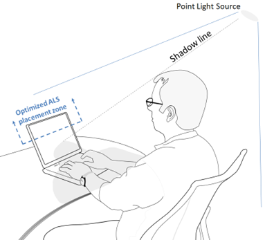
Avoid placing the light sensor in areas of the computer that are likely to be obscured from light sources by shadows or a user's hands, fingers, or arm during normal usage. Figure below illustrates an example user scenario in which a direct light source is behind the user. A shadow is cast over the lower half of the screen and the base of the computer. This scenario suggests optimal light sensor placement near the top of the screen and facing the user.
Make sure the different configurations a device can take (position of the keyboard in tablet mode vs laptop mode for example) do not block the aperture and do not intersect the sensor's field of view.
Finally, make sure the sensor's field of view isn't intersecting with any noisy source of light (camera flash, keyboard backlight, and so on) as these can contribute to additional noise or bad readings. Make sure to consider all the different configurations a device can take when considering the field of view intersecting with noisy sources of light.
Dealing with invalid light sensor data
Under certain conditions, the ambient light sensor field of view may be obstructed by an object or by the user, making it impossible for the sensor to take an accurate reading. For example, such a condition may happen when the user's hand covers the ambient light sensor aperture. Many other cases exist.
The ambient light sensor can indicate this situation to the operating system by sending a new sensor sample with its PKEY_SensorData_IsValid data field set to FALSE. Proper hardware design should minimize the time and scenarios requiring this value to be set to FALSE as such a scenario prevents the system from properly controlling brightness. On an ideal system, the ambient light sensors would always be able to measure the ambient light, and this value would be set to TRUE.
Light sensor filters, lenses, enclosures, and calibration
When engineering a device that includes an ALS, the entire system of mechanical, optical, and electrical components related to the ALS needs to be carefully considered. The following diagram illustrates the key mechanical components that must be considered and understood when integrating and calibrating ambient light sensor hardware with Windows.
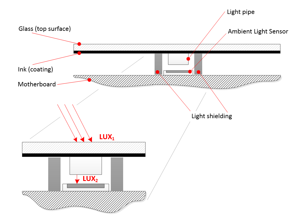
In this diagram, we see the following:
- Glass - outer surface of the screen
- Ink coating - black border around the screen
- Light shielding - prevents light bleed
- Light pipe - gathers and directs light to sensor
- Ambient light sensor
- Motherboard
Note
Light pipes are usually not needed, and in many cases may degrade ALS performance. Please consult with the light sensor manufacturer for guidance regarding these kinds of optical components.
This diagram references two light levels:
$LUX_{1}$: The incident light level for the surroundings of the device at the surface of the display. This level is measured and reported by the ambient light sensor via the sensor platform.
$LUX_{2}$: The incident light level on the surface of the ALS. This is not the correct light level to report via the sensor platform as it does not take into account the attenuation factor of the optics.
The attenuation factor corresponds to how much light is blocked by the various components between the outer surface of the device (typically glass) and the sensing surface of the ALS. Attenuation can be calculated as follows: A = (1 - transmittance)
Important
The ambient light sensor reports the ambient light intensity that it senses. Due to the transmissibility of the optics, the raw ALS readings report attenuated lux values and should not be used without correction. The transmissibility is the characteristics of the optics that reduce ambient light intensity and also reject infrared (IR) light. If the optics are painted with ink for visible appearance, an attenuation factor must be used to compensate for the corresponding reduction in ambient light intensity.
$LUX_{2}$ should always be lower than $LUX_{1}$
The difference between these two lux values is called the attenuation factor. The attenuation factor accounts for the total percentage of light transmittance between the top surface of the glass ($LUX_{1}$) and the bare surface of the ambient light sensor ($LUX_{2}$). This is most drastic when a painted glass surface is used. The OEM, with the support of the sensor IHV, should measure the attenuation factor and correct for it in hardware before exposing the lux value to the operating system.
Note
Transmittance is the ratio of the light level at the surface of the ALS divided by the ambient light level surrounding the device.
In the below example, assume the total percentage of light transmittance between the top surface of the glass and the bare surface of the ambient light sensor is 5%. In order to support the required lux range, the light sensor selected needs to support the following range at the bare sensor:
- $Minimum = 1 lux × 0.05 = 0.05 lux$
- $Maximum = 100,000 lux × 0.05 = 5000 lux$
In the firmware or driver, depending on whether a hardware or software ALS solution is being implemented, the following conversion is used to account for the attenuation factor:
$Output LUX = LUX_{1} = LUX_{2} / (total % _{light _transmittance})$
For a bare ambient light sensor reading of 100 lux, the following is the resultant output lux:
$Output LUX = 100 / 0.05 = 2000 LUX$
The entire system should be calibrated with proper light measurement equipment as well. This example only demonstrates the general considerations for part selection and initial calibration prior to formal calibration. Per-unit factory calibration is strongly encouraged for the best and most consistent user experience. Sensors often have accuracy ranges of +/- 20% from unit to unit, which can be accounted for via per-unit factory calibration.
Also, the field of view is an important factor to consider in ambient light sensor placement and design. The smaller the field of view, the worse the performance of the sensor will be. As a general rule, a 55 degree half angle field of view (110 degrees total) is a fair target. The wider the field of view, the less prone the sensor will be to picking up a single point source of light or an area of shadow that may not accurately reflect the true light environment.
Sensor connectivity with HID and SPB
The following diagrams illustrate how to integrate ALS using the HID protocol, and with an IHV-specific driver for SPB.
Tip
The HID protocol is the recommend path to integrate ALS, making use of the inbox HID drivers in Windows.
HID sensor hardware, driver, and software stack is illustrated below:
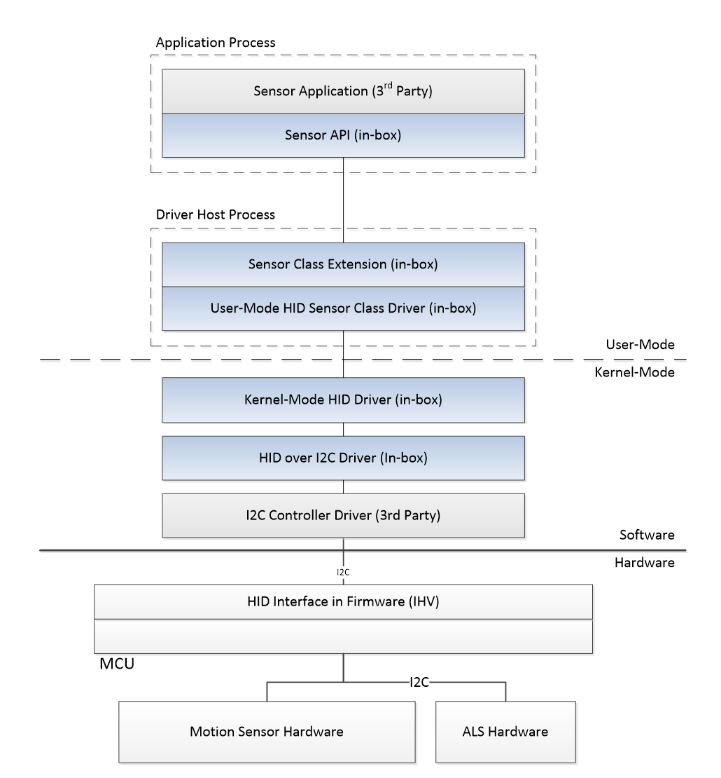
Boxes from top to bottom: Sensor Application, Sensor API, Sensor Class Extension, User-mode HID Driver, HID-I2C Driver, I2C Controller, HID Interface in Firmware, and ALS Hardware
SPB sensor hardware, driver, and software stack is illustrated below:
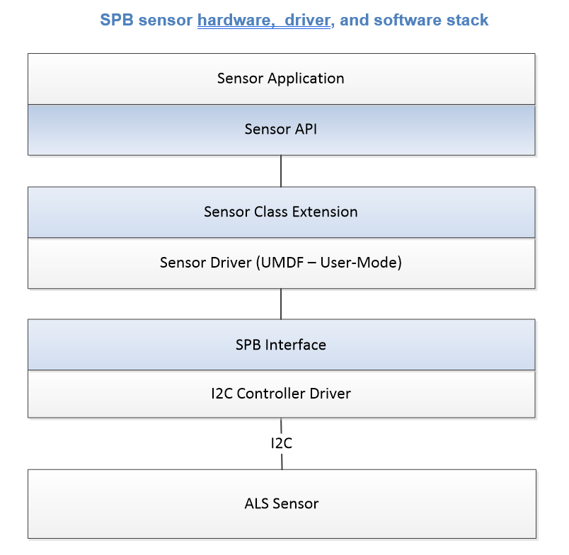
Boxes from top to bottom: Sensor Application, Sensor API, Sensor Class Extension, UMDF User-mode Sensor Driver, SPB Interface, I2C Controller Driver, and ALS Sensor
For more information about integrating sensor hardware via the HID protocol, including HID and I2C, please see Sensor HID class driver.
For more information about integrating sensors via SPB buses, please see the sensor combo sample driver source code on GitHub.
Ambient light sensor calibration
Professional calibration (recommended)
Calibration of the ALS in the integrated system using professional, pre-calibrated sensors in a controlled lighting environment is highly recommended. These pre-calibrated sensors, often called light meters, are available for purchase from electronic equipment vendors and online retailers.
Other calibration techniques
Details on other ALS monitoring and calibration tools are available through the Microsoft Ambient Light Tool article.
Light sensor validation
As a first step, you should always run the Sensors (i.e. Input) Hardware Lab Kit tests to validate the ambient light sensor. Ensure that all Minimum hardware requirements and the Windows Hardware Compatibility Program tests pass.
In order to validate proper functioning of the ambient light sensor:
- Make sure that the DisplayEnhancementService is started.
- Enable auto-brightness and set the slider to 50%.
- Validate that the display brightness changes when the lighting changes.
- Use a light dimmer to slowly ramp environmental light up and down and ensure that the lux values are smoothly ramping up and down. Coarse and discrete light changes result in sub-optimal screen brightness response and should be avoided.
- Use a professional lux meter to ensure that the ALS readings are accurate. At a minimum, verify the following points: 0, 10, 100, 500 and 1000 lux.
- In systems that only customized the ALR curve, test the behavior with users to validate ALR data meets user expectations.
Minimum hardware requirements and the Windows Hardware Compatibility Program
Minimum hardware requirements and Windows Hardware Compatibility Program requirements are fundamental for creating Windows-compatible sensor experiences. Although the programs are optional, we recommend that audio products meet both sets of requirements to ensure basic audio quality.
For more details, see the Windows Hardware Compatibility Program.
The following sections cover recommendations for sensors. To ensure high quality experiences, all devices should be tested against these performance requirements.
| Area | Type of guidance | Which devices should be tested |
|---|---|---|
| Device.Input.Sensor.AmbientLightSensor | Provides component-level guidelines in order to function optimally with the host OS in terms of software interfaces, communication protocols, and data formats. | All integrated ambient light sensors should be tested against these performance requirements. |
| System.Client.Sensor.AmbientLightSensor | Provides system-level guidelines in order to function optimally with the host OS in terms of software interfaces, communication protocols, and data formats. | All integrated ambient light sensors should be tested against these performance requirements. |
Ambient response curve
If an ambient light sensor reports an ambient light response curve, then it must follow:
| Data Field | Data Type | Definition |
|---|---|---|
| PKEY_LightSensor_ResponseCurve | VT_VECTOR | VT_UI4 |
The response curve of the sensor must have at least two points and the gradient must be positive or flat. For more information, see the response curve.
Color capable
Ambient light sensors are not required to detect color. If an ambient light sensor supports color, then the color related properties, thresholds, and data fields must be reported. A color capable light sensor must report the following enumeration property:
| Data Field | Data Type | Definition |
|---|---|---|
| DEVPKEY_LightSensor_ColorCapable | VT_BOOL | Specifies if this light sensor is color capable. |
A color capable light sensor must report one of the following combinations of data fields:
- Lux, kelvins, chromaticity x, chromaticity y
- Lux, chromaticity x, chromaticity y
For more information, see the light sensor data fields.
For the color data fields that the light sensor reports, thresholds must also be supported. A sample must be reported when at least one threshold is met. For more information, see the light sensor thresholds.
Data field properties
Ambient light sensors must report the required data field properties. For more information, please refer to light sensor data fields.
Data types
Ambient light sensors are required to report light data. For more information, see light sensor data fields.
Minimum report interval
Non-color-capable ambient light sensors in Windows are required to support a report interval of 250 milliseconds or less. Color capable ambient light sensors in Windows are required to support a report interval of 1000 milliseconds or less.
Thresholds
Light sensors are required to support thresholds on lux. If absolute thresholds are supported, both the percentage and absolute lux threshold must be met for a data sample to be reported.
Assume the absolute threshold is 1 lux and the percentage threshold is 25%:
| Last sample | Next sample | Result |
|---|---|---|
| 4 lux | 3 lux | The next sample would get reported since the change is greater than or equal to 1 lux from the last reported sample and is greater than or equal to 25% of the last reported sample. |
| 1 lux | 0.5 lux | The next sample would not get reported since the change is less than 1 lux from the last reported sample. |
| 100 lux | 90 lux | The next sample would not get reported since the change is less than 25% of the last reported sample. |
For more information, see light sensor thresholds
Auto brightness preferred
If an ambient light sensor is intended to be used with the auto-brightness feature, then the following enumeration property is required to be reported:
| Data Type | Definition | |
|---|---|---|
| DEVPKEY_LightSensor_AutoBrightnessPreferred | VT_BOOL | Specifies if this light sensor should be the preferred light sensor used for the Windows auto-brightness service. |
There must only one ambient light sensor reporting this property on a system.
Color calibration
Ambient light sensors are not required to support color. If an ambient light sensor does support color, then it is required to be properly calibrated.
While a light source is aimed directly at the sensor:
- The detected ambient lux is either within 10% or 1 lux of the actual incoming light
- The detected chromaticity x and y are within 0.025 of the actual incoming light
Enumeration properties
An ambient light sensor must report DEVPKEY_Sensor_ConnectionType even though this is not a required enumeration property for some other sensors
Is valid
Ambient light sensors are not required to report when light sensor samples are valid or not. If an ambient light sensor does support this, the following data field must be reported:
| Data Field | Data Type | Definition |
|---|---|---|
| PKEY_SensorData_IsValid | VT_BOOL | Indicates if the current data sample is valid. |
If the PKEY_SensorData_IsValid value changes, a sample must be reported regardless of if the thresholds have been met.
Assume the lux threshold is 1 lux:
| Last sample | Next sample | Result |
|---|---|---|
| 100 lux | 100 lux, but the sensor is now blocked (previous sample's PKEY_SensorData_IsValid was true) | The current sample would get reported with 100 lux and PKEY_SensorData_IsValid set to false. |
| 100 lux and was blocked (previous sample's PKEY_SensorData_IsValid was false) | 100000 lux and the sensor is still blocked (PKEY_SensorData_IsValid is false) | No sample is reported. |
| 0 lux and sensor was blocked (previous sample's PKEY_SensorData_IsValid was false) | 0 lux, but the sensor is now unblocked (PKEY_SensorData_IsValid is true) | The current sample would get reported as 0 lux but with PKEY_SensorData_IsValid set to true. |
Light calibration
The auto-brightness service in Windows needs light sensors to report an accurate measurement of the light level in the environment. When the light source is aimed directly at a light sensor that doesn't support color, the reported light level is required to be within 4%, or at least 1 lux of the actual incoming light level
Light range
The auto-brightness service in Windows needs to be able to detect a reasonable range of light levels from 1 to 10,000 lux. If the range is smaller than this, the adjusted auto-brightness may not be able to match the actual brightness of the environment.