Adaptive brightness
Adaptive brightness is the screen brightness set automatically by the system in response to the ambient light sensor reading. Adaptive brightness provides users a more responsive display experience where brightness adapts automatically to the user's environment.
New in Windows 11
The implementation for auto-brightness has been radically simplified for OEMs wishing to integrate light sensors into Windows 11 using a new paradigm, a bucketized ambient light response (ALR) curve. For more information, see Ambient light response curve changes for Windows 11.
The new method does not rely on the previous OEM-configurable lux-to-brightness curve. The default curve is more stable and reliable, plus easier to integrate.
Settings pages have new visuals. Updates to the Display settings page are noted in this article. There is a user toggle for Content Adaptive Brightness Control (CABC).
The following improvements in Windows 10 version 1903 (19H1) are still in place:
- Automatic brightness is enabled by default
- Users can control brightness using the action center slider
- Adaptive brightness registry configuration parameters
Optimizing display brightness steps and transitions
The number of brightness levels that a display device exposes is important. Two approaches are possible:
- Percentage-based: Controlling brightness using percentage values, supporting 101 levels (zero through 100) of backlight control.
- Nits-based (recommended): Controlling brightness using nits values allows for a fined-grained control of backlight levels. And therefore, enables very smooth and accurate brightness transitions.
Windows detects the type of brightness interface exposed by the display driver and selects the most appropriate one. If a display driver only exposes the DXGK_BRIGHTNESS_INTERFACE_2 interface, the system will control brightness using percentage values. If a display driver exposes the DXGK_BRIGHTNESS_INTERFACE_3 interface, Windows 10, version 1809 and later controls brightness using nits values. The DXGK_BRIGHTNESS_INTERFACE_3 interface is ignored on down-level Windows versions. If both DXGK_BRIGHTNESS_INTERFACE_2 and DXGK_BRIGHTNESS_INTERFACE_3 interfaces are exposed by the display driver, Windows 10, version 1809 and later will control brightness using nits values. Down-level Windows versions will control brightness using percentage values.
Brightness and display considerations
If the system supports setting brightness in nits by having the display drive expose the DXGK_BRIGHTNESS_INTERFACE_3 interface, the display should be properly calibrated. Calibration should be performed at various intensities by measuring nits values with a high-quality nits meter at different locations of the display while displaying a white background. Tools to measure display brightness are called luminance meters or brightness meters, and are available for purchase from electronic equipment vendors and online retailers.
The display implementation must be carefully optimized. Specifically:
- Ensure that display is capable of dimming smoothly across all the accessible brightness levels.
- Sufficient display brightness levels should be exposed to ensure smooth dimming. At least 101 levels are recommended.
Controlling brightness using nits values
Starting with Windows 10, version 1809, the system will control brightness using nits on devices which display driver exposes the DXGK_BRIGHTNESS_INTERFACE_3 interface. The nit (candela per square meter) is an International System of Units (SI) unit of luminance. When a device bears a properly calibrated display and properly calibrated sensor, brightness control should work out of the box. There is no need for any ALR curve on these devices.
For these systems, it is critical that light sensors and display are accurately calibrated. Windows 10, version 1809 tolerates small inaccuracies that may occur during the manufacturing process of these systems. Placement of the components, glass transparency, and similar factors can greatly influence the lux and nits. Therefore, calibration on nits-based brightness systems should be done at least once with the final form factor design as opposed to doing calibration on development form factors and applying the result to the final form factor.
Per-device calibration during production of each device gives the best end results.
Controlling brightness using percentage values
Systems that don't support nits brightness control must support percentage values. On percentage systems, a mapping between the backlight percentages and luminance values is necessary. The mapping of backlight percentages to luminance values should follow an exponential pattern. On nits-based brightness systems, since the each nit level is expected to be calibrated, an inbox percentage to nits mapping is provided. This inbox percentage to nits mapping uses human vision and color science research to provide a perceptually linear brightness slider. As long as the nit levels are calibrated correctly as described in DXGK_BRIGHTNESS_INTERFACE_3, the perceptual luminance difference between zero percent and 1% will be automatically equivalent to the perceptual luminance difference between 1% and 2%, and so forth.
Human vision is more sensitive to small changes in screen brightness output at low light levels, thus more backlight levels should be allocated to the lower brightness range to accommodate smoother transitions. The difference between 1% and 2% in nits should be smaller than the difference from 10% and 11%, for example. This means that 50% of the screen's maximum luminance will not be mapped to the 50% backlight level.
For an acceptable user experience, the lowest level of brightness (0%) must result in a low, but readable display. Users can get into inextricable situations when setting brightness to 0% on devices that map that value to 0 nits, as the controls to brighten the screen are not visible anymore. The screen must be bright enough at 0% for the user to interact with the UI on the display. On devices supporting the DXGK_BRIGHTNESS_INTERFACE_3 interface, 0% is automatically restricted to a minimum of 5 nits by Windows.
Ambient light response curve changes for Windows 11
Some concerns were raised regarding the Windows 10 implementation of adaptive brightness:
- Poor ambient light sensor readings, especially in very dark or very bright environments
- Display panels that are unable to adapt to every percentage or nits-value
- Difficulty finding the optimal lux to nits mapping
These concerns result in:
- Continual fluctuations in display brightness due to inaccuracy of the ambient light sensor (ALS)
- Slight changes in nits prominent in low lighting environments
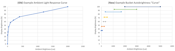
To address these concerns, we changed the ambient light response to a bucketized curve, as show in the figure below. OEMs can opt-out of the bucketized curve through customization options.
The following image compares changes to the default ALR curve from Windows 10 to Windows 11. An example of a default curve is on the left, and a bucketized default curve for Windows 11 is on the right. The curves illustrated below are only examples of curves that could be set as defaults. The actual default curve for a device depends on a number of factors and can vary depending on the device manufacturer.
Note
Systems upgrading from Windows 10 to Windows 11: No changes to hardware or firmware outside of existing Windows 10 adaptive brightness requirements, these are internal changes to Windows 11. Existing Windows 10 adaptive brightness capable systems will experience the new bucketized curve when updated to Windows 11.
Bucketed auto brightness functional overview
To reduce frequent display brightness fluctuations in response to fluctuating readings from the ALS, we introduced bucketed auto brightness. A range of lux values are mapped to a single target brightness percentage value. The display brightness is then transitioned to the target percentage value. On DXGK_BRIGHTNESS_INTERFACE_2 interface-based devices, the target percentage is used as it is. On DXGK_BRIGHTNESS_INTERFACE_3 interface-based devices, the target percentage is converted into the corresponding nits value and used. Based on our experiments under various lighting conditions, the lux ranges are partitioned into seven different overlapping buckets and assigned a corresponding display brightness target. A reading from the ALS is mapped to a target brightness using this look up table. The buckets introduce the necessary hysteresis effect that prevents fluctuations in the display brightness for non-significant changes in ALS readings. Overlapping buckets help with smooth transitions between the buckets when the ALS reading changes widely.
Bucketed auto brightness always starts with the second bucket, 55% target display brightness, as that is the most common lighting condition users experience. As the brightness changes, the target transition moves to the corresponding higher or lower bucket. The slider is animated in response to the bucket transitions.
Here is a sample sequence of events with the inbox bucketed ALR curve:
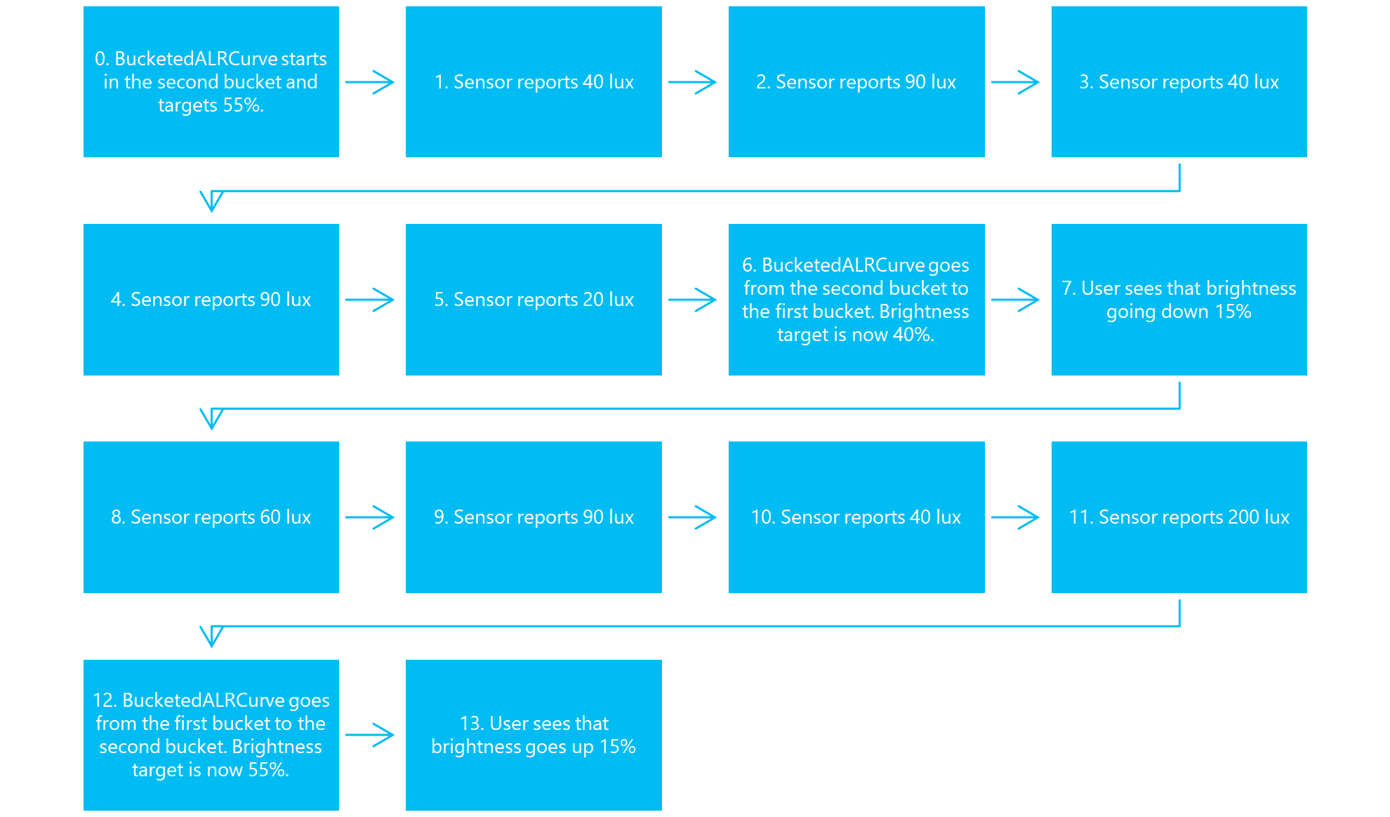
BucketedALRCurve starts in the second bucket and targets 55%.;Sensor reports 40 lux;Sensor reports 90 lux;Sensor reports 40 lux;Sensor reports 90 lux;Sensor reports 20 lux;BucketedALRCurve goes from the second bucket to the first bucket. Brightness target is now 40%;User sees that brightness going down 15%;Sensor reports 60 lux;Sensor reports 90 lux;Sensor reports 40 lux;Sensor reports 200 lux;BucketedALRCurve goes from the first bucket to the second bucket. Brightness target is now 55%. User sees that brightness goes up 15%
For this sequence, the brightness only went up and down twice overall even though the ambient light fluctuated frequently.
The device starts in the second bucket. When the sensor fluctuates from 40-90 lux, the brightness percent never changes since 40 and 90 lux both belong in the second bucket.
When the sensor reports a sample of 20 lux, the device goes to the first bucket as 20 lux is no longer in the second bucket. The brightness is then stable for a couple of lux values. Note that the 90 and 40 lux values do not move the brightness back to the second bucket as these values exist in the first bucket.
When the sensor reports a sample of 200 lux, the device goes to the second bucket as 200 lux exceeds the maximum lux value of the first bucket.
Outdoor scenarios
Some nits devices support boost ranges. This means that the brightness can exceed 100% if auto brightness allows it. By setting the sixth and seventh buckets past 100%, these buckets will be triggered when the users go into direct sunlight on devices that support boost ranges.
Extremely dark scenarios
Many sensors do not handle very dark scenarios well, sending fluctuating ALS values. Because the lowest bucket goes up to 100 lux, brightness should not change frequently in these dark environments.
Auto brightness registry keys
OEM customizations mentioned in this section are with respect to the following registry key in Windows 11:
Computer\HKEY_LOCAL_MACHINE\SOFTWARE\Microsoft\Windows NT\CurrentVersion\AdaptiveDisplayBrightness\{23B44AF2-78CE-4943-81DF-89817E8D23FD}
| Key | Format | Usage |
|---|---|---|
| AutobrightnessLuxToNitsCurve | REG_SZ | The LUT for ALS lux reading to target nits curve. Example: "1:8,2:25,5:35,10:60,20:90,40:90,100:130,400:170,700:200,2000:400,3000:500,4500:700" |
Brightness hysteresis for custom ALR curve in Windows 11
Most systems will leverage a bucketized auto brightness curve by default in Windows 11. Hysteresis and transitions will not be used in the default bucketized curve. The following parameters should be used when an OEM opts-in to using a customized ALR curve.
| Key | Format | Usage |
|---|---|---|
| UpperBrightnessHysteresisLut | REG_SZ | The LUT for the upper bound brightness hysteresis threshold. Example: "10000:50000,20000:40000,50000:10000" represents a LUT defined by (input 10000millinits, hysteresis 50000millinits), (20000, 40000), and (50000, 100000) in that specific order |
| LowerBrightnessHysteresisLut | REG_SZ | The LUT for the lower bound brightness hysteresis threshold. |
Brightness transitions for custom ALR curve in Windows 11
| Key | Format | Usage |
|---|---|---|
| MinBrightnessTransitionNitDelta | REG_DWORD | Minimum nit delta needed to trigger a brightness transition defined in millinits |
| DefaultBrightnessTransitionInterval | REG_DWORD | Default brightness transition internal time between two transition points defined in milliseconds |
| MinBrightnessTransitionInterval | REG_DWORD | Minimum brightness transition internal time between two transition points defined in milliseconds |
| MaxBrightnessTransitionInterval | REG_DWORD | Maximum brightness transition internal time between two transition points defined in milliseconds |
Test cases
This section discusses testing the ambient light sensor.
ALS calibration
Ensure the ambient light sensor is properly calibrated for a given set of ambient lights. Verify that the sensor lux readings are accurate.
ALS calibration applies to
All systems supporting adaptive brightness
ALS calibration setup and tools
- A controllable (dimmable) source of light capable of generating different lux levels
- A light meter measuring light in lux
- MonitorBrightnessApp or SensorExplorer to visualize the values reported by the ambient light sensor
ALS calibration test procedure
- Set the light meter next to the device. The light meter should be as close to the ambient light sensor as possible without negatively interacting with it.
- Start the MonitorBrightnessApp
- In a dark room, use the source of light to change the level of ambient light to different lux levels
- Read the lux meter and the value reported by the MonitorBrightnessApp. The values should be identical
ALS calibration test variations
- Use different types of controllable lights, such as incandescent lights, CFL, and LED
- Use different angles
ALS calibration evaluation (pass or fail)
The lux values reported by the MonitorBrightnessApp should be identical to the values reported by the light meter.
ALS calibration triage notes
Work with your sensor hardware manufacturer to understand how to calibrate the sensor.
ALS granularity
Make sure the ambient light sensor changes are fine grained, with no delay
ALS granularity applies to
All systems supporting adaptive brightness
ALS granularity setup and tools
- Use a light source with a controllable dimmer to finely ramp the ambient light up and down. The light source should be able to smoothly ramp the light up and down.
- Use the MonitorBrightnessApp in the BrightnessTests folder to visualize the ambient light sensor response.
ALS granularity test procedure
- In a dark room, use the dimmer to smoothly ramp the light level up and down
- Use the MonitorBrightnessApp to visualize the ambient light sensor response. The response should match the changes applied to the dimmer.
ALS granularity evaluation (pass or fail)
The ambient light sensor response should closely match the changes applied to the dimmer. A linear change to the dimmer should result in a linear response from the ambient light sensor. The ALS response should not be discreet. A change to the dimmer should be immediately visible in the MonitorBrightnessApp with no delay.
ALS granularity triage notes
Work with your sensor hardware manufacturer to understand how the ambient light sensor transitions can be smoothen out and how delays can be reduced.
Sleep transitions
Make sure the ambient light sensor is still functional when coming out of sleep or when the lid is opened.
Sleep transitions applies to
All systems supporting adaptive brightness
Sleep transitions setup and tools
- Use a light source to switch the ambient light on and off.
- Use the MonitorBrightnessApp in the BrightnessTests folder to visualize the ambient light sensor response.
Sleep transitions test procedure
- In a dark room, switch the device on or open the lid.
- Use the MonitorBrightnessApp to visualize the ambient light sensor reading. Make sure the sensor reads a low lux value.
- Keep the MonitorBrightnessApp running throughout the following steps
- Close the lid or switch the device off
- Switch the light on, make sure the ambient light is bright
- Open the lid or switch the device on
- Connect to the desktop and observe the value in the MonitorBrightnessApp. The lux value should immediately reflect the actual ambient light.
Sleep transitions evaluation (pass or fail)
The ambient light sensor should send a sample reading when exiting connected standby or when the lid is opened.
Sleep transitions triage notes
Work with your sensor hardware manufacturer to understand how the ambient light sensor can be fixed.
Smooth transitions
Make sure the display panel smoothly changes brightness.
Smooth transitions applies to
All systems supporting adaptive brightness
Smooth transitions setup and tools
- Use the BrightToDim.ps1 script, found in the BrightnessTests folder, to linearly ramp the brightness up and down. Switch your device to manual brightness. The script will ramp the screen brightness down from 100 to 0.
- Optional: use a brightness (nits) meter to measure the screen brightness
Smooth transitions test procedure
- Make sure the screen is displaying as much white as possible For example, open Notepad and maximize it on the screen.
- Start the BrightToDim.ps1 script and observe the screen behavior. The screen should transition as smoothly as possible, without any jumps in brightness.
Smooth transitions evaluation (pass or fail)
The screen brightness should smoothly transition up and down, there should not be any visible jumps in brightness.
Smooth transitions triage notes
Work with your hardware manufacturer to understand how display panel brightness changes can be made smooth.