Note
Access to this page requires authorization. You can try signing in or changing directories.
Access to this page requires authorization. You can try changing directories.
This PC thermal management design guide provides information about how to determine the PC temperature values that are "too hot" and "too cold."
Making these determinations is a key requirement for a design that delivers a good PC user experience. And also, these thresholds help to choose the first mitigating action to take for PC components that reside in multiple thermal zones.
Designing the temperature thresholds
Variables and assumptions
The following factors influence a PC's thermal behavior:
Hardware design
The importance of good hardware design cannot be over-stressed. For more information, see Hardware thermal modeling and evaluation.
Environment
These are external factors that contribute to the thermal behavior of the system. The software can only influence the environment by notifying the user that thermal constraints are an issue—for example, by displaying the thermal-failure-to-boot logo. The user must move to a different environment for these factors to change:
Sunlight radiation
The intensity and angle of the sunlight impacting the screen or any part of the system.
Ambient temperature
The temperature of the environment.
Airflow
With or without air circulation. Windy or in a computer case.
Humidity
Dry or humid.
Workload and power consumption
The assumption here is that workload and power consumption are proportional to each other. In other words, the more work a PC or component does, the more power it consumes and the more heat it generates. Although this might not be true in all cases, this simplified model is more or less sufficient here. This is where software mitigations come in. By reducing the workload, less heat is generated and the PC keeps operating.
When designing and modeling the hardware, take into account the parameters mentioned in the preceding list. Please use worst-case values for the environment. The only parameter that can be directly controlled by software is the workload.
Thermal fundamentals
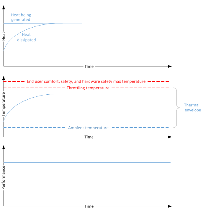
Consider a PC's thermal behavior when it is running a constant workload. As the workload starts, the PC's hardware components such as the CPU and GPU generate heat and increase the temperature. As the temperature increases relative to the ambient temperature, the PC starts to dissipate heat faster until eventually the heat generation is equal to the heat dissipation, and the temperature reaches steady state. For the entire duration of this constant workload, since there is no throttling involved, the performance and throughput are constant.
The following diagram shows the relationship between heat generation, temperature, and performance when no throttling is involved. Notice that the PC's temperature stays within the thermal envelope, as bounded by the ambient temperature and throttling temperature.
Now consider a PC's thermal behavior when it is running a different workload that is also constant but more resource intensive. As this workload executes, the heat generated is much higher than what the system is capable of dissipating to the ambient environment, and as a result the temperature rises steadily. Without passive cooling, the temperature will continue rise until eventually the system will become too hot and adversely impact end user comfort and safety. Hardware can be damaged as well at high temperatures. Thermal throttling helps ensures that the PC does not reach these high temperatures. When the temperature rises over a pre-defined throttling temperature trip point, the system starts throttling performance. As a result, the heat generation is reduced and gradually—after the heat generation and dissipation equalize—the system temperature reaches the steady state.
The following diagram shows the relationship between heat generation, temperature, and performance when performance is throttled to reduce heat generation.
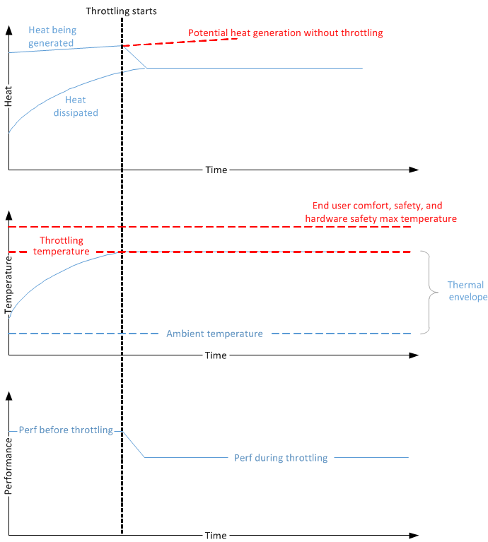
In both cases shown in the preceding diagrams, the workloads must operate within a thermal envelope to ensure that the system temperature does not exceed safe limits. The envelope starts with the ambient temperature and ends with the throttling temperature. Also in both cases, the heat generation and dissipation eventually reach a balanced state, and the system temperature is stabilized.
Defining a thermal envelope
A well-designed PC should have as large of a thermal envelope as possible, providing users a long-lasting, mitigation-free experience. As shown in the preceding diagrams, the thermal envelope has a lower bound determined by the ambient temperature. It is bounded above by the throttling temperature. While the ambient temperature is not a variable that system designers can control, the upper bound can be pushed higher by good hardware design. For more information, see Hardware thermal modeling and evaluation. But even assuming that hardware is not the major limitation, other important factors must be considered when defining the thermal envelope.
The desired operating range should be as large as possible without encroaching on these limiting factors:
Safety
Temperature of the system must first ensure that users do not suffer any injuries from using the system. This requirement applies mostly to the skin temperature sensor.
Hardware protection
Temperature should prevent system components from "melting" or otherwise causing damage due to heat. This requirement applies mostly to component temperature sensors—for example, a sensor that sits on top of the processor.
Government regulation
All systems should meet applicable industry standards (such as IEC 62368) for consumer electronics safety.
Hardware thermal modeling and evaluation
Software as complement to hardware design
When designing hardware, it's of key importance to keep thermal management in mind. Selecting low-power parts, placing hot components far from one another, and incorporating thermal insulation are only a few examples of how hardware can greatly improve the thermal experience. These methods cannot be replaced in software. As such, the software solution only serves as a complement to the hardware design in the overall thermal experience.
Hardware goal
Typical workloads should not need any form of software thermal mitigation to run. The hardware thermal design should be able to disperse heat for these workloads by itself.
Modeling
Modeling is an iterative process to achieve the hardware goal previously described. In this process, do not factor in any software mitigations. Rely solely on the hardware capabilities and adjust as necessary.
Define a typical workload. Depending on the platform of the system, from phone to server, each system should have a standard set of typical workloads. These should not be intense workloads such as HD video conferencing, but rather a more average workload like browsing the web or listening to music.
Model system and individual component power consumption on typical workloads since heat will not be spread across the chassis uniformly. Pay particular attention to the components that consume most power, such as the processor.
Based on the workload power consumption estimation, model the rise in component and skin temperature over time.
Adjust the system's mechanical design to ensure that the component temperature is within the hardware safety limit and user comfort limit over all ambient temperatures. Some methods for addressing mechanical design issues are:
- Improve the heat dissipation capability by adding better heat-conducting materials.
- Increase the delta temperature between the skin and the internal temperature by adding isolation layers.
Repeat steps 1 through 4 until satisfied.
Build the hardware and evaluate.
Evaluation
For every hardware revision, a temperature and power measurement against representative workloads must be performed to evaluate the thermal behavior, and the mechanical design should be modified as needed.
The following steps are recommended to perform such thermal evaluation:
Define a thermal measurement test matrix:
- The matrix should cover both normal and maximum ambient temperature.
- The matrix should include all typical workloads identified as part of the thermal modeling, and for every workload, data should be captured for at least one hour.
- The matrix should be executed in multiple PCs multiple times to generate consistent results.
For every workload defined in the test matrix, capture the following data:
- System and component power consumption data.
- Ambient, internal component, and skin temperature data.
- Software traces to detect thermal throttling, performance metrics, and processor utilization.
The skin and component temperature data directly indicates the maximum skin temperature that the system might reach and whether this temperature is acceptable. Consider how much thermal headroom the system might have before critical shutdown. The performance metrics data will help determine whether the system is delivering the required performance. The trace data recorded by the thermal throttling software shows the thermal throttling percentage. The power consumption data and the CPU utilization data can help to determine what factors influence the temperature changes.
The following table provides an example of such data collection for a PC with the following configuration:
Configuration
- Machine name: Thermal-Test-1
- Average ambient temperature: 23oC
- Thermal zone trip point (_PSV): 80oC
| Category | Subcategory | Video streaming | Casual gaming | Fishbowl | 3D gaming | TDP |
|---|---|---|---|---|---|---|
| Workload setup | Full-screen 720p H.264 video streaming through Wi-Fi | Game name CPU utilization |
Classic IE with 100 fish | Game name CPU utilization |
CPU and GPU 100% | |
| Power consumption | System power | |||||
| SoC power | ||||||
| Display power | ||||||
| Backlight power | ||||||
| Temperature | Max SoC temperature | |||||
| Max skin temperature | ||||||
| Performance metrics | Average frame rate | Average frame rate | Average frame rate | Average frame rate |
Windows thermal management framework
The Windows thermal management framework provides a comprehensive solution for software thermal management. The following examples show how to implement thermal management. With proper thermal modeling, validation, and effective thermal mechanical design, all systems should be able to deliver a smooth user experience on most workloads on most targeted ambient temperatures. Where thermal mitigation is required, Windows provides an effective and extensible thermal management architecture.
Windows thermal management supports both active and passive cooling. With active cooling, fans turn on to circulate air and help cool the system. With passive cooling, devices reduce device performance in response to excessive thermal conditions. Reducing performance lowers the power consumption, and thus generates less heat.
The Windows thermal management framework relies on the policies specified by system designers to enforce thermal management on the system. At a high level, designers must specify how the reading obtained from each thermal sensor is affected by each component. Without these specifications, Windows cannot thermally manage the system. Thus it is the responsibility of each system designer to characterize their system thermally in order to achieve a good thermal design.
Although systems are not required to use the Windows thermal management framework, it is the recommended solution because of its tight integration with the operating system. However, regardless of the thermal management solution used, all Modern Standby PCs must adhere to the HCK requirements for diagnostic purposes.
Thermal management architecture
The Windows thermal management architecture is based on the ACPI concept of thermal zones. The ACPI thermal zone model requires cooperation between the firmware, operating system, and drivers. This model abstracts the sensors and cooling devices from the central thermal management component through well-defined interfaces. The thermal management enhancements are based on Chapter 11 of the ACPI 5.0 specification. The Windows thermal management framework implements a subset of the capabilities described in this chapter.
The essential components of the model are:
- Platform thermal zone definitions described to Windows via the firmware. A thermal zone is an abstract entity that has an associated temperature value. The operating system monitors this temperature so that it can apply thermal mitigation to devices within the zone. The zone contains a set of functional devices that generate heat, and a subset of devices whose heat generation can be controlled by adjusting performance.
- A temperature sensor that represents the region's temperature. The sensor must implement the Read Temperature interface to retrieve the temperature of a zone from firmware or a Windows temperature driver.
- A thermal cooling interface to enable drivers for devices within thermal zones to implement passive-cooling actions. Each managed driver must have the cooling interface to participate in Windows thermal infrastructure.
- A centralized thermal manager that orchestrates cooling by interpreting the thermal zone definitions and invoking the interfaces at the required times. The thermal manager is implemented in the Windows kernel and requires no work from system designers.
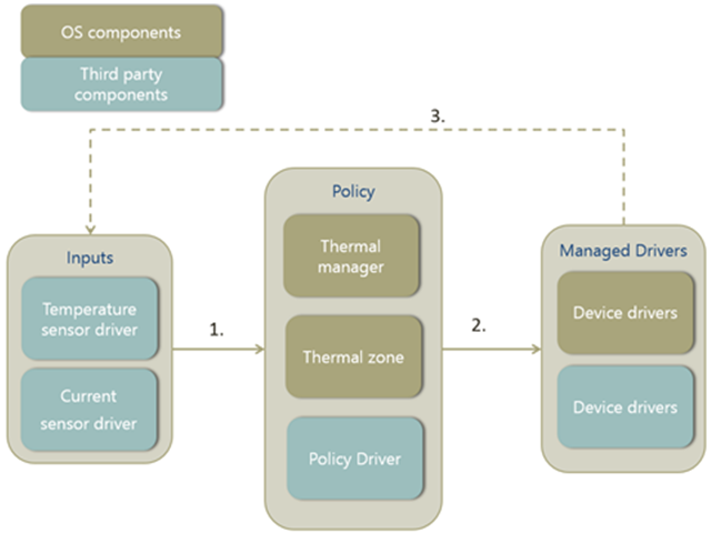
The following block diagram is an overview of the Windows thermal management architecture. The main components are the thermal manager, thermal zone, managed drivers, and temperature sensor. The thermal zone dictates the throttling behavior of its managed devices based on constraints provided by the thermal manager. The algorithm used by the thermal manager uses the temperature reading of the sensor for the thermal zone as its input parameter.
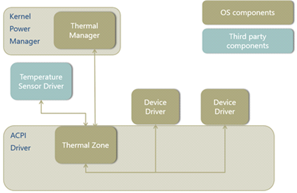
The thermal zones in the system must be described in ACPI firmware and exposed to the thermal manager through ACPI. With the configuration information, the thermal manager knows how many thermal zones need to be managed, when to start throttling each thermal zone, and which devices are a part of the zone. To monitor temperature, the system designer provides support in ACPI firmware for thermal notifications.
When the thermal manager is notified of a thermal event in an enumerated zone, it will start to periodically evaluate the temperature of the zone and determine the thermal throttling performance percentage to apply to devices in the thermal zone. This evaluation is done by the thermal throttling algorithm that is outlined in the ACPI specification. Then the thermal manager notifies all the devices in the zone to throttle performance by a specific percentage and the device drivers translate the throttling percentage to a device-class-specific action to reduce performance. The periodic evaluation and throttling will stop when the thermal zone temperature falls below the throttling threshold temperature and no more throttling is required.
Feedback loop
Another way to think of the thermal management architecture is in terms of inputs, policy director, and managed devices. In the following block diagram, the inputs to the feedback loop are the temperature and electrical current. These inputs are used to determine the thermal policy to implement. The thermal manager relies on the temperature input exclusively, and the policy driver may use whatever input it desires. The thermal zone then applies that policy to its managed drivers. After the policy is applied, the sensors will update their values and close the loop.
The following block diagram shows the three stages of the thermal response model. Inputs from temperature and electrical current sensors provide information to help determine what thermal policy to apply. This policy gets applied to the managed drivers, which then affects the readings on the sensors. The process repeats in a feedback loop.
Responsibilities of system implementers
As mentioned above, a number of components are required to have a complete Windows thermal solution. The architecture of the thermal framework is specifically designed so that the responsibilities of the hardware vendor and system integrator can be separated.
Required components for partners to implement are:
Sensors
The temperature sensor drivers should be provided by the hardware vendor. Given that temperature sensors do not need knowledge of the thermal zones that rely on them, their functionalities should be standard across different platform designs. Custom sensors for policy drivers, such as current sensors, are also the responsibility of the hardware vendor.
Thermal zones
The thermal zones can be defined by the hardware vendor and/or system integrator. All systems must have at least one thermal zone that implements a critical shutdown temperature (and hibernate temperature, if supported), which can be done by the hardware vendor or system integrator. However, for other thermal zones that monitor specific devices or the skin temperature for mitigation, it's common for the system integrator to have more specific knowledge of the thermal behavior of the system. Thus, these thermal zones are usually implemented by the system integrator.
Thermal cooling interface for device drivers
The developer who writes the driver for the device that is to be thermally managed should also be the one to implement the cooling interface. The device driver uses this interface to opt into the thermal management framework. Device drivers have specific knowledge of the capabilities of their devices. These same drivers must implement the thermal cooling interface so that it can properly interpret the actions requested by the thermal zone.
Sensors
Sensors provide inputs to determine what the thermal policy should be. Windows supports only temperature sensors as inputs to the thermal manager. However, a policy driver can additionally take inputs from custom drivers, such as a current sensor driver.
Temperature sensor
The temperature sensor provides the following modes of functionality:
- Continuously monitors temperature changes without the involvement of the thermal manager or thermal zone.
- Notifies the thermal manager when the temperature crosses the threshold defined by _PSV, _HOT, or _CRT.
- Responds to temperature queries and returns the current temperature value.
The following diagram shows how the temperature monitoring functions during throttling. The ACPI firmware or the temperature sensor driver should notify the thermal manager when the temperature reaches a predefined threshold such as _PSV, _HOT or _CRT, and then respond to the periodic queries from the thermal manager for the current temperature. The period of the temperature query is defined by _TSP.
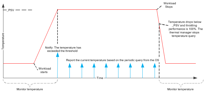
To make sure that the thermal manager will be always notified when the temperature exceeds the threshold, the temperature sensor interrupt should be always wake-able (even when the system is in Modern Standby and the SoC is in a low-power state). If the temperature sensor interrupt is not always wake-able, then at least the interrupt should be configured as level-triggered to avoid potential interrupt loses.
A thermal sensor can be used by multiple thermal zones, although there can be no more than one thermal sensor in a thermal zone.
We recommend that the sensor hardware to be accurate to +/- 2oC.
The temperature reported by _TMP or a temperature sensor driver may be the actual value of a sensor, or an extrapolated value based on several sensors.
This is usually provided by the hardware vendor. Windows supports two implementations for monitoring temperature:
- Temperature sensor driver
- ACPI-based
Implementation 1: Temperature sensor driver
The temperature sensor driver simply reports the temperature of the sensor. The ACPI driver will issue one outstanding IOCTL with the sensor driver to detect a crossing of one of the trip points. In addition, ACPI may issue one IOCTL with no time-out to read the current temperature. The sensor driver should handle cancellation of the read IOCTL, if it is canceled while waiting for the time-out to expire. The temperature sensor must implement the following interface:
typedef struct _THERMAL_WAIT_READ {
    ULONG Timeout;
    ULONG LowTemperature;
    ULONG HighTemperature;
} THERMAL_WAIT_READ, *PTHERMAL_WAIT_READ;

#define IOCTL_THERMAL_READ_TEMPERATURE\
        CTL_CODE(FILE_DEVICE_BATTERY, 0x24, METHOD_BUFFERED, FILE_READ_ACCESS)
The following table describes the input and output parameters for the temperature-reading interface.
| Parameter | Description |
|---|---|
| Timeout | The time to wait before returning temperature data, in milliseconds. 0 indicates the temperature should be read immediately, with no wait. -1 indicates the read should not time out. |
| LowTemperature | The lower threshold for returning the new temperature. As soon as the temperature drops below the low temperature threshold, the driver should complete the IOCTL. If the temperature is already below the low temperature, the IOCTL should be completed immediately. |
| HighTemperature | The upper threshold for returning the new temperature. As soon as the temperature rises above the high temperature threshold, the driver should complete the IOCTL. If the temperature is already above the high temperature, the IOCTL should be completed immediately. |
| IOCTL return value | A ULONG-sized output buffer that will return the current temperature, in tenths of a degree Kelvin. |
One temperature sensor can be used by one thermal zone or multiple thermal zones. To specify which temperature sensor should be used for a thermal zone, the thermal _DSM should be specified on the thermal zone, and should implement function 2. (For backwards compatibility, the temperature sensor driver can be loaded on top of the thermal zone stack. However, the preferred implementation is to have the sensor driver separate from the thermal zone stack.) This _DSM is defined as follows:
Arguments Arg0: UUID = 14d399cd-7a27-4b18-8fb4-7cb7b9f4e500 Arg1: Revision = 0 Arg2: Function = 2 Arg3: An empty package Return A single Reference to the device that will return the temperature of the thermal zone.
The thermal zone must also specify a dependency on the temperature sensor device with _DEP. Here's a simple example for _DSM implementation of a sensor device.
Device(\_SB.TSEN) {
    Name(_HID, "FBKM0001")     // temperature sensor device
}

ThermalZone(\_TZ.TZ01) {
    Method(_DSM, 0x4, NotSerialized){
        Switch (ToBuffer(Arg0)) {
            Case (ToUUID("14d399cd-7a27-4b18-8fb4-7cb7b9f4e500")) {
                Switch (ToInteger(Arg2)) {
                    Case(0) {
                        // _DSM functions 0 and 2 (bits 0 and 2) are supported
                        Return (Buffer() {0x5})
                    }
                    Case (2) {
                        Return ("\_SB.TSEN")
                    }
                }
            }
        }
    }

    Method(_DEP) {
        Return (Package() {\_SB.TSEN})
    }

    // Other thermal methods: _PSV, etc.

}
For more information, see Device-Specific Method for Microsoft thermal extensions.
Implementation 2: ACPI-based
The ACPI firmware should support _TMP and Notify 0x80, as defined in the ACPI specification. The advantage of this approach is that it does not require any additional drivers be installed on the system. However, this approach is limited to interacting with resources that are accessible through ACPI operation regions.
Thermal policy control
Thermal zone
A thermal zone is an individual thermal throttling entity. It has its own thermal throttling characteristics, such as trip points, throttling sample rate, and throttling equation constants. One thermal zone might include multiple thermal throttling devices, each of which can contribute to temperature increases in the thermal zone. All devices in the same thermal zone must follow the same constraints applied to the thermal zone.
To make sure thermal zones and their parameters are defined accurately, system designers should:
- Identify hot spots in the system's chassis, and determine how these hot spots dissipate heat to the temperature sensors. (Ideally, thermal sensors are sitting at the hot spots on the system, except for skin temperature sensors.)
- Characterize the system's temperature relationship. Map the temperature sensor readings to the component temperature and the skin temperature.
Overthrottle threshold
Starting with Windows 10, a new feature called a thermal zone state, has been introduced into Windows thermal management, along with one state: overthrottled. When a thermal zone exceeds the device’s designed throttle level, the thermal manager will notify the operating system components that the system is overthrottled. This notification allows the system to reduce workload to improve the thermal state.
The thermal manager maintains a global count of the number of thermal zones that are in the overthrottled state. When the count increases above zero (0), the thermal manager sends out a Windows Notification Facility (WNF) notification to the system, indicating that it is overthrottled. When the number of overthrottled zones returns to zero (0), the thermal manager sends out another WNF notification to the system, indicating there are no overthrottled zones.
To specify the overthrottle threshold for a thermal zone, the thermal _DSM should be specified on the thermal zone, with function 3 implemented. This _DSM is defined as follows:
Arguments Arg0: UUID = 14d399cd-7a27-4b18-8fb4-7cb7b9f4e500 Arg1: Revision = 0 Arg2: Function = 3 Arg3: An empty package Return An Integer value with the current overthrottle threshold, expressed as a percentage.
Here's an example _DSM which indicates that the zone is overthrottled, at throttle levels 0% through 49%.
 ThermalZone (TZ4) {
    Name (_HID, "QCOM24AE")
    Name (_UID, 0)
    Name(_TZD, Package (){\_SB.CPU4, \_SB.CPU5, \_SB.CPU6, \_SB.CPU7})
    Method(_PSV) { Return (3530) }
       Name(_TC1, 1)
       Name(_TC2, 1)
       Name(_TSP, 1)
       Name(_TZP, 0)
       // _DSM - Device Specific Method
       // Arg0: UUID Unique function identifier
       // Arg1: Integer Revision Level
       // Arg2: Integer Function Index (0 = Return Supported Functions)
       // Arg3: Package Parameters
       Method(_DSM, 0x4, NotSerialized) {
          Switch (ToBuffer(Arg0)) {
             Case (ToUUID("14d399cd-7a27-4b18-8fb4-7cb7b9f4e500")) {
                Switch (ToInteger(Arg2)) {
                   Case(0) {
                      // _DSM functions 0 and 3 (bits 0 and 3) are supported
                      Return (Buffer() {0x9})
                   }
                   Case (3) {
                      Return (50)  // overthrottled below 50%
                   }
                }
             }
          }
       }
 } // end of TZ4
The overthrottle threshold will be re-read when a Notify(0x81) is received in reference to the thermal zone.
Implementing ACPI objects
The following table lists all ACPI objects that need to be implemented in ACPI firmware to define a thermal zone.
| Category | Control method |
|---|---|
| Identify the devices contained within the zone |
|
| Specify thermal thresholds at which actions must be taken |
|
| Describe passive cooling behavior |
|
| Describe active cooling behavior |
|
| Set active / passive cooling policy |
|
| Minimum Throttle Limit |
|
| Report temperature |
|
| Notify the thermal manager |
|
| Specify temperature sensor device |
|
Minimum throttle limit
The minimum throttle limit is a Microsoft thermal extension _DSM method that creates a lower bound for _PSV requested of a throttled device. In other words, it determines how much a thermal zone limits the performance of devices it controls. If present, the minimum throttle _DSM will be read at boot and any time the thermal zone receives ACPI Notify (0x81). At every iteration of the passive cooling algorithm, the following is used to compute the change in performance limit (DP) that the thermal manager applies to devices in the zone:
DP [%] = _TC1 × (Tₙ – Tₙ₋₁) + _TC2 × (Tₙ – Tₜ) We then use the following to compute the actual performance limit:
Pₙ = Pₙ₋₁ – DP With the minimum throttle limit (MTL) implemented, this second equation changes to:
Pₙ = max(Pₙ₋₁ – DP, MTL) To specify the minimum throttle limit for a thermal zone, the thermal _DSM should be specified on the thermal zone, with function 1 implemented. This _DSM is defined as follows:
Arguments Arg0: UUID = 14d399cd-7a27-4b18-8fb4-7cb7b9f4e500 Arg1: Revision = 0 Arg2: Function = 1 Arg3: An empty package Return An Integer value with the current minimum throttle limit, expressed as a percentage.
Here's a simple example for _DSM limiting throttle no less than 50 percent.
ThermalZone(\_TZ.TZ01) {
    Method(_DSM, 0x4, NotSerialized) {
        Switch (ToBuffer(Arg0)) {
            Case (ToUUID("14d399cd-7a27-4b18-8fb4-7cb7b9f4e500")) {
                Switch (ToInteger(Arg2)) {
                    Case(0) {
                        // _DSM functions 0 and 1 (bits 0 and 1) are supported
                        Return (Buffer() {0x3})
                    }
                    Case (1) {
                        Return (50)
                    }
                }
            }
        }
    }
Thermal manager in kernel
The Windows thermal manager is implemented as part of the Windows kernel. It monitors the temperature of all thermal zones and applies thermal throttling as appropriate.
Every time the thermal manager queries the ACPI driver for the current temperature, it will perform a calculation on how much thermal throttling performance percentage it should apply to all thermal throttling devices in the thermal zone. The thermal limit is evaluated and applied when the passive cooling threshold (_PSV) is exceeded, and at every temperature sampling interval (_TSP) until the temperature is cooled below it and the thermal limit returns to 100 percent. The hardware must detect when the _PSV has been exceeded and must signal that via a hardware ACPI event notification.
Thermal throttling algorithm
The thermal throttling algorithm uses the following equation, which is defined in the ACPI specification:
DP [%] = _TC1 × ( Tₙ – Tₙ₋₁ ) + _TC2 × (Tₙ – Tₜ) where
Tₙ = current temperature reading of the temperature sensor in the thermal zone in tenths of a degree Kelvin. Tₙ₋₁ = temperature from the previous reading. Tₜ = target temperature in tenths of a degree Kelvin (_PSV). DP = performance change required. This is a linear value between 0 (fully throttled) and 100 percent (unthrottled), which is to be applied to each cooling device in the zone. This equation describes the feedback loop between the temperature changes and the throttling performance. In each iteration of the loop, the temperature delta between the current and previous temperature readings requires performance P to decrease by DP percent. The DP value is the amount of thermal throttling to apply. Many cooling devices do not have a linear thermal response to cooling mitigations. In these devices, the thermal limit is a hint to the device to indicate how much cooling is required. Each cooling device will have its own mapping of this linear value to device-specific thermal mitigations. Throttling device performance reduces power consumption and heat generation, which causes the temperature to decrease.
The two constants, _TC1 and _TC2, control how aggressively thermal throttling is applied in this feedback loop. The bigger _TC1 is, the more aggressively thermal throttling is used to maintain a stable temperature. The bigger _TC2 is, the more aggressively thermal throttling is used to push the temperature near the trip point.
The following table provides an example of how the thermal manager calculates and applies the DP. This example uses the following parameter values:
Configuration
- _PSV = 325oK
- _TC1 = 2
- _TC2 = 3
- _TSP = 5000 milliseconds
- Assume the temperature continuously rises by 1 degree every 5 seconds.
The rightmost column in the following table (labeled P) indicates the throttled performance level that results from enforcing the constraints specified by these parameters.
| Iteration | Time | Tₙ | DP | P |
|---|---|---|---|---|
| 1 | 0 seconds | 326oK | = 2 × 1 + 3 × 1 = 5% | 95% |
| 2 | 5 seconds | 327oK | = 2 × 1 + 3 × 2 = 8% | 87% |
| 3 | 10 seconds | 328oK | = 2 × 1 + 3 × 3 = 11% | 76% |
| 4 | 15 seconds | 320oK | = 2 × 1 + 3 × 4 = 14% | 62% |
| 5 | 20 seconds | 330oK | = 2 × 1 + 3 × 5 = 17% | 45% |
| ... |
Policy driver
By default, the algorithm used to determine the throttling percentage as dictated by ACPI specs is used for all thermal zones. As previously described, this algorithm is a based solely on the temperature sensor attached to the thermal zone, which can be limiting.
If a different algorithm is preferred, the system designer can implemented a policy driver to embody the preferred algorithm. A policy driver sits on top of the thermal zone stack for the zone it controls. For this zone, the policy driver's algorithm can be used in place of the ACPI algorithm in the thermal manager. The policy driver's algorithm has the capability to consider any information it can access as input. The policy decisions made by the driver are passed to the thermal manager, which logs the information and passes it to the thermal zone to carry out.
Using a policy driver for a thermal zone means that the policy driver—not ACPI and not the operating system—is solely responsible for deciding when to throttle a zone and by how much.
If a policy driver is present, all trip points, all thermal constants, the minimum throttle limit, and so on, are completely ignored. The operating system has no insight into why the thermal zone is set at its current throttling level. Some benefits come with using a policy driver instead of a propriety solution. A policy driver leverages the built-in process of throttling devices. Anything that a thermal zone can do to provide thermal mitigation can be done by a policy driver. In addition, diagnostics for Windows thermal management are automatically inherited.
The thermal policy interface has been updated to include a new parameter to indicate whether or not the zone is overthrottled. This parameter is initialized to FALSE. Old policy drivers will be unaware of the new parameter, and new drivers will know that the new parameter is supported, when they detect a policy version of '2'.
#define TZ_ACTIVATION_REASON_THERMAL      0x00000001
#define TZ_ACTIVATION_REASON_CURRENT      0x00000002

#define THERMAL_POLICY_VERSION_1          1
#define THERMAL_POLICY_VERSION_2          2

typedef struct _THERMAL_POLICY {
    ULONG           Version;
    BOOLEAN         WaitForUpdate;
    BOOLEAN         Hibernate;
    BOOLEAN         Critical;
    ULONG           ActivationReasons;
    ULONG           PassiveLimit;
    ULONG           ActiveLevel;
    BOOLEAN         OverThrottled;
} THERMAL_POLICY, *PTHERMAL_POLICY;
The policy driver can indicate that the thermal zone is overthrottled, by completing the policy IOCTL with the OverThrottled parameter set to TRUE. When thermal conditions improve, the thermal policy driver can then complete the IOCTL with OverThrottled reset to FALSE, to indicate that the thermal zone has recovered. Windows will not require the policy driver to be throttling when the overthrottle flag is set.
Thermally managed devices
Thermal zones control the thermal behavior of managed devices through their kernel mode drivers. One thermal throttling device might reside in multiple thermal zones. When multiple thermal zones requests different thermal throttling performance percentages, the thermal manager picks the minimal thermal throttling performance percentage to apply to the thermal throttling device.
Many cooling devices do not have linear thermal response to cooling mitigations. In these cases, the thermal limit is a hint to the device of the degree of cooling required. Each cooling device will have its own mapping of this linear value to its specific thermal mitigations.
As each device driver is loaded, ACPI will query for the Thermal Cooling Interface and register each responding device as a cooling device. Later, when passive cooling is in process and the thermal limit for a zone has changed, ACPI will call this interface on each cooling device in the zone. The cooling device will then map the provided thermal limit to its specific cooling characteristics, and implement appropriate cooling mitigations. Note that if the cooling device appears in multiple thermal zones, the thermal limit that constrains the device the most (that is, the lowest percentage) is passed to the device.
Note Windows provides built-in implementations of thermal throttling for processors, backlight, and ACPI control method battery.
Thermal cooling interface
Windows provides the extension points for device drivers to register as thermal throttling devices and to receive the thermal throttling percentage request. The device is then responsible for translating that percentage to an action that makes sense for itself.
Devices that want to be added as a thermal throttling device should first add the _HIDs into the thermal zone thermal device list and then implement the following set of interfaces. As each device driver is loaded, ACPI will query for this interface and register each responding device as a cooling device. Later, when passive cooling is in process and the thermal limit for a zone has changed, ACPI will call this interface on each cooling device in the zone. The cooling device will then map the provided thermal limit to its specific cooling characteristics, and implement appropriate cooling mitigations. Note that if the cooling device appears in multiple thermal zones, the thermal limit that constrains the device the most (that is, the lowest percentage) is passed to the device.
//
// Thermal client interface (devices implementing
// GUID_THERMAL_COOLING_INTERFACE)
//

typedef
_Function_class_(DEVICE_ACTIVE_COOLING)
VOID
DEVICE_ACTIVE_COOLING (
    _Inout_opt_ PVOID Context,
    _In_ BOOLEAN Engaged
    );

typedef DEVICE_ACTIVE_COOLING *PDEVICE_ACTIVE_COOLING;

typedef
_Function_class_(DEVICE_PASSIVE_COOLING)
VOID
DEVICE_PASSIVE_COOLING (
    _Inout_opt_ PVOID Context,
    _In_ ULONG Percentage
    );

typedef DEVICE_PASSIVE_COOLING *PDEVICE_PASSIVE_COOLING;

typedef struct _THERMAL_COOLING_INTERFACE {
    //
    // generic interface header
    //
    USHORT Size;
    USHORT Version;
    PVOID Context;
    PINTERFACE_REFERENCE    InterfaceReference;
    PINTERFACE_DEREFERENCE  InterfaceDereference;
    //
    // Thermal cooling interface
    //
    ULONG Flags;
    PDEVICE_ACTIVE_COOLING ActiveCooling;
    PDEVICE_PASSIVE_COOLING PassiveCooling;
} THERMAL_COOLING_INTERFACE, *PTHERMAL_COOLING_INTERFACE;

#define THERMAL_COOLING_INTERFACE_VERSION 1
Processor
For a processor, the thermal manager communicates the thermal throttling percentage to the processor power manager (PPM). Thermal throttling of processors is a built-in feature of Windows.
Processor aggregator
The processor aggregator device allows core parking as a thermal mitigation. Zones can specify core parking as a thermal mitigation if the processor aggregator device is a member of a thermal zone. Processors are not required to be throttled for core parking to occur. This implementation works in parallel with logical processor idling (LPI). Note that this is still subject to the caveats of core parking. In particular, any work affinitized to a parked core will cause the core to run.
Device(\_SB.PAGR) {
    Name(_HID, "ACPI000C")
}
ThermalZone(\_TZ.TZ01) {
    Name(_TZD, Package() {"\_SB.PAGR"})
    // Other thermal methods: _PSV, etc.
}
Graphics
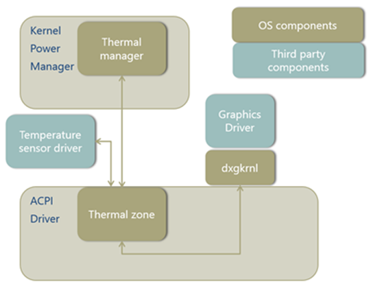
In order for a third-party graphics miniport driver to be thermally managed, it must interact with the Windows graphics port driver, Dxgkrnl.sys. Dxgkrnl.sys has the thermal cooling interface and passes any throttle requests down the stack to the miniport driver. It is the responsibility of the miniport driver to translate the request to an action specific to its device.
The following block diagram shows the architecture of the thermal zone that controls the GPU.
Backlight
Reducing the backlight can dramatically improve thermal conditions on a mobile platform. Windows recommends that while operating, the system display brightness is never thermally limited to less than 100 nits.
For backlight control, the thermal manager communicates the thermal throttling percentage to the monitor driver, Monitor.sys. Monitor.sys will decide the actual backlight level setting based on this thermal input and other inputs in Windows. Then Monitor.sys will apply the backlight level setting through either ACPI or the display driver.
Note that if the thermal zone temperature that includes the backlight continues rising, the requested thermal throttling percentage might eventually drop to zero percent. The backlight level implementation in ACPI or display driver should ensure that the minimal brightness level available for performance controls is still visible for end users.
Note While operating, the system display brightness is never thermally limited to less than 100 nits.
Battery
Another main heat source in the system is battery charging. From a user's perspective, charging should be reduced and even completely halted under constrained thermal conditions. However, battery charging should not be hindered under normal use cases.
Note We recommend that battery charging is not throttled while the system is (1) idle and within the ambient temperature range below 35oC, or (2) under any conditions while the ambient temperature is below 25oC.
The Windows Control Method Battery miniclass driver, Cmbatt.sys, uses the Thermal Cooling Interface directly, as described above. Firmware is responsible for taking the current thermal limit into account when engaging charging. A new ACPI control method is necessary to set the thermal limit for charging. This method is implemented as a Device Specific Method (_DSM), as defined in the ACPI 5.0 specification, Section 9.14.1.
To apply the thermal throttling percentage, Cmbatt.sys will evaluate the Device Specific Method (_DSM) control method to request the ACPI firmware to set the thermal limit for charging. Within the _DSM control method, a GUID is defined to indicate the thermal limit.
| Arg # | Value | Description |
|---|---|---|
| Arg0 | 4c2067e3-887d-475c-9720-4af1d3ed602e | UUID |
| Arg1 | 0 | Revision |
| Arg2 | 1 | Function |
| Arg3 | Integer value from 0 to 100 | Thermal limit for battery charging. Equivalent to calculated percentage passive throttle. |
| Return value | N/A | No return value |
Active cooling
From the point of view of the operating system, a platform has two strategies that it can use to implement fan control:
Implement one or more ACPI thermal zones with active trip points to engage/disengage the fan.
The Windows thermal framework supports active cooling devices at a very basic level. The only device supported inbox is an ACPI fan, and it can only be controlled with on/off signal.
Implement a proprietary solution to control the fan (via drivers, an embedded controller, etc.).
While Windows does not control the behavior of proprietary solutions for fans, Windows does support fan notifications to thermal manager for all implementations including embedded controllers so that diagnostic information and telemetry can be collected. Thus fan exposure to the operating system is required for all Modern Standby PCs and strongly recommended for all others.
Note that the implementation for active cooling is completely separate from the passive cooling mitigations previously discussed.
Fan control by ACPI thermal zone
Windows supports the ACPI 1.0 D-state-based fan definition. (For more information, see the ACPI specification.) Thus, the control is limited to fan on and off. The driver for the fan is provided in the Windows ACPI driver, Acpi.sys.
- The temperature sensor reads the temperature has crossed a trip point and issues Notify(0x80) on the associated thermal zone.
- The thermal zone reads the temperature with the _TMP control method and compares the temperature to the active trip points (_ACx) to decide whether the fan needs to be on or off.
- The operating system puts the fan device in D0 or D3 which causes the fan to turn on or off.
The following block diagram shows the control flow for a fan controlled by an ACPI thermal zone.

Scope(\_SB) {
    Device(FAN) {
        Name(_HID, EISAID("PNP0C0B"))
        // additional methods to turn the fan on/off (_PR0, etc.)
    }

    ThermalZone(TZ0) {
        Method(_TMP) {...}
        Name(_AC0, 3200)
        Name(_AL0, Package() {\_SB.FAN})
    }
}
Multiple-speed fan in ACPI
To achieve multiple speeds for a fan using ACPI 1.0, there are two options:
- The thermal zone can contain multiple "fans", when only one physical fan exists. Having more "fans" on at one time translates to faster fan speed. For more information, see the example of this option in Section 11.7.2 in the ACPI 5.0 specification.
- When the fan is on, it can decide for itself how fast to spin. Systems with embedded controllers, for example, can choose this option.
Proprietary solution for fans
Windows needs to be able to detect fan activity with either implementation. When a platform uses the ACPI thermal model, Windows is responsible for turning the fan on and off and therefore already knows when it is active. When a proprietary solution is used to control the fan, Windows needs notification that the fan is running. To enable this, Windows will support a partial subset of the ACPI 4.0 fan extensions, which are listed in the following table.
| Feature | Description | Supported |
|---|---|---|
| _FST | Returns the fan's status. | yes |
| Notify(0x80) | Indicates the fan's status has changed. | yes |
| _FIF | Returns fan device information. | no |
| _FPS | Returns a list of fan performance states. | no |
| _FSL | Sets the fan performance state (speed). | no |
Windows will use the _FST object to determine if the fan is running (Control field is nonzero) or off (Control field is zero). Windows will also support Notify(0x80) on the fan device as an indication that _FST has changed and needs to be reevaluated.
A fan that implements the _FST object is not required to be in a thermal zone's _ALx device list, but it can, as an option, be in this list. This option enables a hybrid solution in which a fan is typically controlled by a third-party driver, but can be controlled by the OS thermal zone if the third-party driver is not installed. If a fan is in an _ALx device list and is engaged by the thermal zone (placed in D0), the _FST object is required to indicate a nonzero Control value.
For all fans, Windows will use the following algorithm determine the state of the fan:
- If a fan is in D0 (as a result of a thermal zone's _ACx trip point being crossed), it is engaged.
- If a fan is in D3 and does not support the ACPI 4.0 extensions, it is disengaged.
- If a fan is in D3 and supports the ACPI 4.0 extensions, the operating system will check _FST's Control field for a nonzero value to see if the fan is engaged.
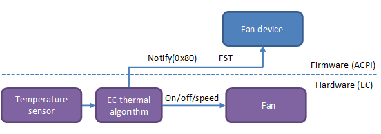
Example 1: Hardware fan control
In this example, a fan is controlled by an embedded controller.
- The embedded controller decides to start or stop the fan based on its own internal algorithm.
- After starting or stopping the fan, the embedded controller issues a Notify(0x80) on the fan device.
- The operating system evaluates _FST and reads the new state of the fan.
The following block diagram shows the control flow for a fan controlled by an embedded controller.
The following ASL example defines a "FAN" device that can notify the operating system of changes in the fan state:
Scope(\_SB) {
    Device(FAN) {
        Name(_HID, EISAID("PNP0C0B"))
        Name(_FST, Package() {0, 0, 0xffffffff})

        // \_SB.FAN.SFST called by EC event handler upon fan status change
        Method(SFST, 1) {
            // Arg0 contains the new fan status
            Store(Arg0, Index(_FST, 1))
            Notify(\_SB.FAN, 0x80)
        }
    }

    // Omitted: EC event handler
}
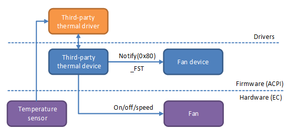
Example 2: Driver fan control
In this example, a third-party driver is controlling the fan.
- The driver decides to start or stop the fan based on its own internal algorithm.
- The driver modifies the state of the fan and evaluates a custom control method (SFST) on its thermal device.
- The thermal device control method updates the fan device's _FST contents and issues Notify(0x80) on the fan device.
- The operating system evaluates _FST and reads the new state of the fan.
The following block diagram shows the control flow for a fan controlled by a third-party driver.
Scope(\_SB) {
    Device(FAN) {
        Name(_HID, EISAID("PNP0C0B"))
        Name(_FST, Package() {0, 0, 0xffffffff})
    }

    Device(THML) {
        Name(_HID, "FBKM0001")
        Method(SFST, 1) {
            // Arg0 contains the new fan status
            Store(Arg0, Index(\_SB.FAN._FST, 1))
            Notify(\_SB.FAN, 0x80)
        }
    }
}
Fan presence
A platform indicates that there is a fan on the system by including a fan device (PnP ID PNP0C0B) in the ACPI namespace. Windows will take the presence of this device as an indication that the system has a fan, and the absence of this device as an indication that the system has no fan.
Guidance specific to Modern Standby
The Windows thermal management framework is a part of the kernel and ships with all Windows systems. Thus, the material above applies to all machines. However, various types of machines require additional guidance more specific to Modern Standby.
Modern Standby brings the smart phone power model to the PC. It provides an instant on, instant off user experience that users have come to expect on their phone. And just like on the phone, Modern Standby enables the system to stay fresh, up-to-date, and reachable whenever a suitable network is available. Windows 10 supports Modern Standby on low-power platforms that meet specific Windows certification requirements.
Modern Standby PCs are highly mobile devices in a thin and light form factor. Further, Modern Standby PCs are always on and in the ACPI S0 state. In order to deliver a robust and reliable customer experience, the entire system—from the mechanical design to firmware and software implementation—must be designed with critical attention to thermal characteristics. Thus, all Modern Standby PCs must adhere to thermal requirements.
Modern Standby requirements
All Modern Standby PCs must pass the following HCK tests:
- All Modern Standby PCs must have at least one thermal zone for which a critical shutdown temperature (_CRT) is defined. For x86 systems, we recommend defining a critical hibernate temperature (_HOT) to trigger the saving of user data. _HOT must be lower than _CRT, and _CRT should be lower than the firmware fail-safe thermal trip point.
- Each thermal zone must report actual temperature on the sensor (_TMP). The test runs a varying workload on the PC, and the temperature is expected to change.
In addition, we recommend that each PC includes at least one temperature sensor for the SoC.
Active cooling requirements
Modern Standby PCs that use fans must adhere to the following additional requirements, which are tested in HCK:
- The fan must be exposed to the operating system. For more information, see Fan presence.
- The operating system must know at all times whether the fan is on or off. Even while in idle resiliency in Modern Standby, any changes in fan activity must wake the SoC to update the status. For more information about implementing fan notifications, see Fan control by ACPI thermal zone.
- The fan must not turn on while the PC is in Modern Standby. With a realistic workload during Modern Standby, which is whenever the screen is off, the fan must not turn on.
From a user perspective, the PC appears to be turned off when it is in Modern Standby. Users expect a PC in Modern Standby to behave as though it is in the system "sleep" state. Thus, users expect the fan to never come on, just as in traditional PCs during sleep. If the fan does come on, users might hear it and/or feel the hot air circulating and think that the computer is not working correctly. Therefore, the fan should not turn on while in Modern Standby. For more information about the required behavior, see HCK test requirements for modern standby PCs.
These requirements imply that the cooling policy when the screen is turned on might need to be different from when the screen turned off. The PC might use active cooling while the screen is on, but it must rely only on passive cooling when the screen is off. The active trip point for the fan might be much lower when the screen is on than when it's off. For the ACPI implementation, _ACx would have to be updated on entry to Modern Standby. For proprietary solutions, please make sure to update the policy in the embedded controller.
Processor throttling
The PPM communicates the maximum, desired and minimal performance levels to the PEP. Under thermal throttling conditions, the maximum performance level should equal the throttling performance requested by the thermal manager. The PEP then sets the CPU's physical voltage and frequency based on the PPM's performance level requirements.
Fan Noise Signal
Starting in Windows 11, devices can send a fan noise signal to the OS for use in resource management decisions, with the goal of providing users with a cool and quiet experience. This opt-in interface allows firmware to send fan RPM information to the OS as a value from 0 (fan off) to Max RPM, which the OS can use in resource management decisions to cool the device as needed. This contributes to two major benefits:
- Quiet User Experience: Fan noise and hot air blowing are a significant source of customer dissatisfaction. This is especially true when the user is not expecting heavy fan activity, such as when the device is running a low amount of work or no foreground work.
- Improved Battery Life: Higher fan speeds result in more power usage, which causes faster battery drain while on DC and slower charging while on AC.
Currently, this signal can be used to manage Search Indexer tasks, and there are plans to enable additional background tasks to consume this signal as well.
The following diagram summarizes how fan noise signal is sent in the layers from firmware to software.
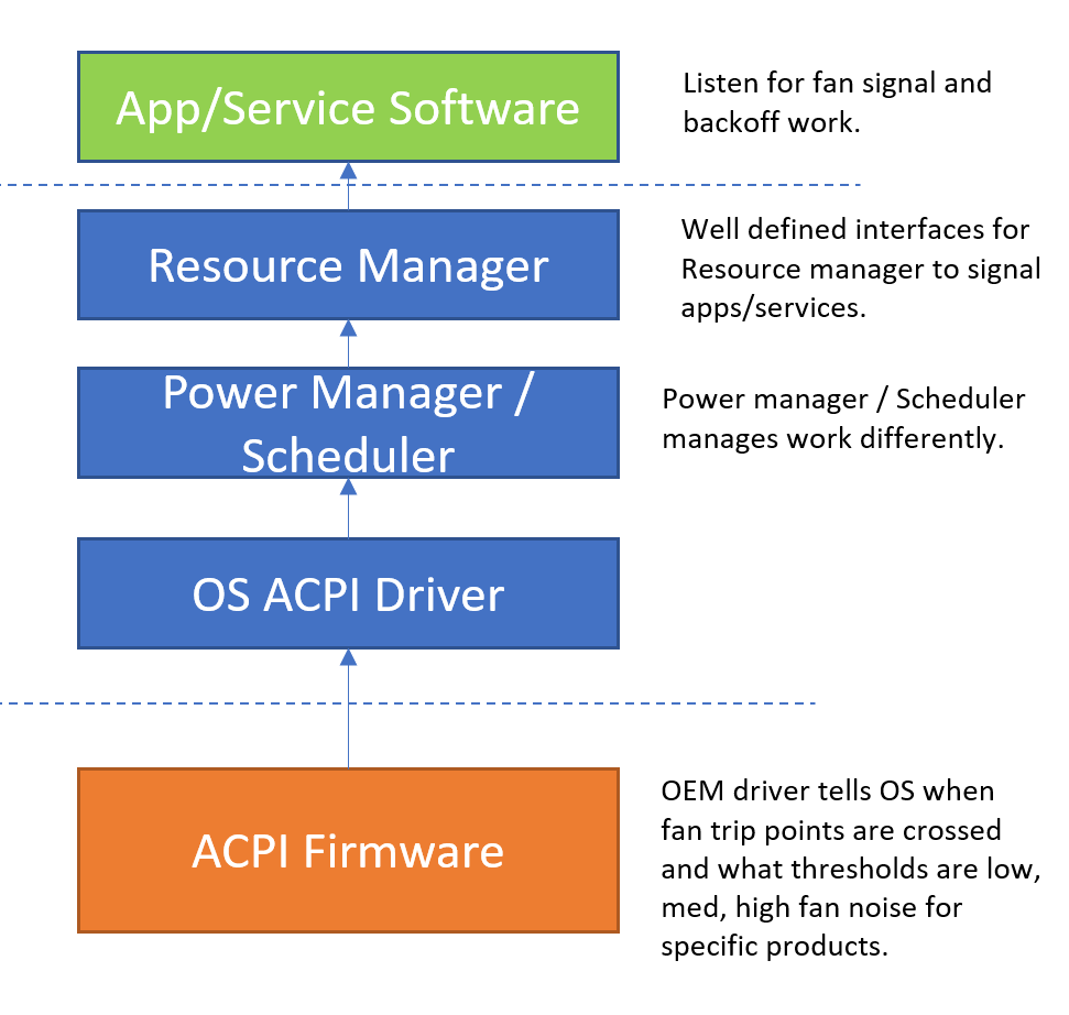
How Fan Noise Signal Works
ACPI Interface Details
Below are the four functions of Device Specific Method (_DSM, UUID: A7611840-99FE-41ae-A488-35C75926C8EB) used to support this feature. Information on _FST (Fan Status) can be found on section 11.3.1.4 of the ACPI specification and in Example 1: Hardware fan control of Thermally Managed Devices
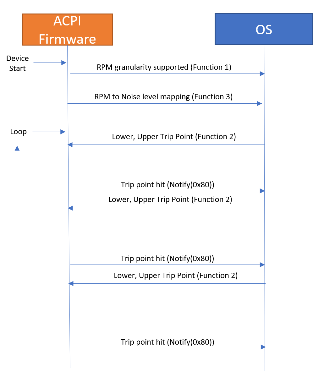
The following diagram summarizes the flow of how these functions are used.
The following block diagram shows the control flow for a fan controlled by an embedded controller, including the Notify(0x80) control method.
Note
Fan Noise Signal would not control Fan RPM but instead notify the OS there is fan noise that requires moving CPU resource from background tasks to complete priority work.
Enumerate Functions (Function 0)
For the operating system to interact with the platform, an ACPI device must be exposed through the Namespace. This Device must include a _CID object containing EISAID(“PNP0C0B”). This device’s scope must contain the following _DSM definition indicating which _DSMs the device supports.
| UUID | Revision | Function | Description |
|---|---|---|---|
A7611840-99FE-41ae-A488-35C75926C8EB |
0 |
0 |
Enumerate functions |
Return: In order to indicate support for functions 0 through 3 listed above, the Enumerate Functions function (function 0) should return 0xF. Please refer to section 9.1.1 of the ACPI spec for more information.
Get Fan Trip Point Support Function (Function 1)
Hardware tells OS what’s supported in terms of RPMs.
| UUID | Revision | Function | Description |
|---|---|---|---|
A7611840-99FE-41ae-A488-35C75926C8EB |
0 |
1 |
Get fan trip point support |
Arguments
Arg0: UUID: A7611840-99FE-41ae-A488- 35C75926C8EB
Arg1: Revision: 0
Arg2: Function: 1
Arg3: An empty Package
Return: An integer value containing the granularity supported for fan trip points, in RPMs. If non-zero, OS may select trip points which are a multiple of the notification granularity. For example, with a granularity of 200, OSPM would be allowed to select trip points at 0, 200, 400, 600, etc. RPMs. A value of 0 indicates trip points are not supported.
Set Fan Trip Points Function (Function 2)
OS communicates to hardware what the next notification trip point is; hardware notifies OS when that happens.
| UUID | Revision | Function | Description |
|---|---|---|---|
A7611840-99FE-41ae-A488-35C75926C8EB |
0 |
2 |
Get fan trip points |
Arguments
Arg0: UUID: A7611840-99FE-41ae-A488-35C75926C8EB
Arg1: Revision: 0
Arg2: Function: 2
Arg3: A Package containing the lower and upper trip points. (2 element int. Lower at index 0, Upper at index 1)
OSPM will only select trip points which are a multiple of the trip point granularity specified in function 1. When the actual speed of the fan goes above or below the upper/lower trip points, the platform should issue Notify(0x80) on the fan device. OSPM will then evaluate _FST (Fan status) to determine the current fan speed. If the fan speed is already outside of the specified trip points when the trip points are set, the platform should immediately issue Notify(0x80).
The upper trip point will be a multiple of granularity. The lower trip point will be (multiple of granularity) + 1 (lower trip point < upper trip point). When RPM is 0, OS will set lower trip point to 0, and upper trip point to 1.
Return: None.
Get Fan Operating Ranges Function (Function 3)
Mapping between RPM –> Impact. Please note that only one fan (the one closest to the SoC) can implement this interface, it must implement all 3 functions plus function 0 from section 9.1.1 of the ACPI spec.
| UUID | Revision | Function | Description |
|---|---|---|---|
A7611840-99FE-41ae-A488-35C75926C8EB |
0 |
3 |
Get fan operating ranges |
Arguments
Arg0: UUID: A7611840-99FE-41ae-A488-35C75926C8EB
Arg1: Revision: 0
Arg2: Function: 3
Arg3: An empty Package.
Return: A Package containing the following format:
Package () {
	Impact1MaxRPM,		// Integer (DWORD)
	Impact2MaxRPM, 		// Integer (DWORD)
	Impact3MaxRPM, 		// Integer (DWORD)
	MaxRPM				// Integer (DWORD)
}
| Field | Format | Description |
|---|---|---|
Impact1MaxRPM |
Integer (DWORD) |
Maximum RPMs for fan impact range 1. |
Impact2MaxRPM |
Integer (DWORD) |
Maximum RPMs for fan impact range 2. Must be >= Impact1MaxRPM. |
Impact3MaxRPM |
Integer (DWORD) |
Maximum RPMs for fan impact range 3. Must be >= Impact2MaxRPM. |
MaxRPM |
Integer (DWORD) |
Maximum RPMs the fan can operate at. Must be >= Impact3MaxRPM. |
This table is used to derive the RPM range for each of the fan impact levels:
| Impact Score | Lower RPM Value | Upper RPM Value |
|---|---|---|
1 |
1 |
Impact1MaxRPM |
2 |
Impact1MaxRPM + 1 |
Impact2MaxRPM. |
3 |
Impact2MaxRPM + 1 |
Impact3MaxRPM |
4 |
Impact3MaxRPM + 1 |
MaxRPM |
If an impact range is not used by a platform (for example, if the fan transitions directly from impact range 2 to impact range 4), it can indicate this by setting the Max RPM for the unused impact range equal to the max RPM for the lower impact range.
Example Mapping
| Value Sent to OS | Fan RPM | User Experience | RPM Ceiling |
|---|---|---|---|
0 – Low |
1-4000 RPM (<=25 dBA) |
Fan not on or on with low annoyance |
Impact1MaxRPM = 4000 |
1 – Medium |
4001-5000 RPM (25-30 dBA) |
Fan on with medium annoyance |
Impact2MaxRPM = 5000 |
2 – Medium-High |
5001-6000 RPM (30-36 dBA) |
Fan on with medium-high annoyance |
Impact3MaxRPM = 6000 |
3 – High |
6001+ RPM (36+ dBA) |
Fan on with high annoyance |
MaxRPM = 9000 |
Example ASL Code
    ...

    // _DSM - Device Specific Method
    // Arg0: UUID Unique function identifier
    // Arg1: Integer Revision Level
    // Arg2: Integer Function Index (0 = Return Supported Functions)
    // Arg3: Package Parameters
    Method(_DSM, 0x4, NotSerialized) {
            If(LEqual(Arg0, ToUUID("A7611840-99FE-41ae-A488-35C75926C8EB"))) {
                Switch (ToInteger(Arg2)) {
                    Case(0) {
                        // _DSM functions 0 through 3 are supported
                        Return (Buffer() {0xf})
                    }
                    Case(1) {
                        // Report 200 RPM granularity for trip points
                        Return (\_SB.FAN0.GRAN)
                    }
                    Case(2) {
                        // Save lower RPM trip point
                        Store(DeRefOf(Index(Arg3, 0)), \_SB.FAN0.LRPM)
                        // Save upper RPM trip point
                        Store(DeRefOf(Index(Arg3, 1)), \_SB.FAN0.URPM)
                        // Configure hardware for the trip points, Tell EC to set fan speed trip point.
                        \_SB.FAN0.CRNF()
                        Return (0)
                    }
                    Case(3) {
                        Return (Package(4) {
                            4000, // 1-4000 RPM is impact score 1
                            5000, // 4001-5000 RPM is impact score 2
                            6000, // 5001-6000 RPM is impact score 3
                            9000})// 6001-9000 RPM is impact score 4
                    }
                    Default {
                        Return(Buffer(One) { 0x00 }) // Guid mismatch
                    }
                }
            }
            Else {
                Return(Buffer(One) { 0x00 }) // Guid mismatch
            }
    }

} // end of FAN0
}
Testing and Tracing
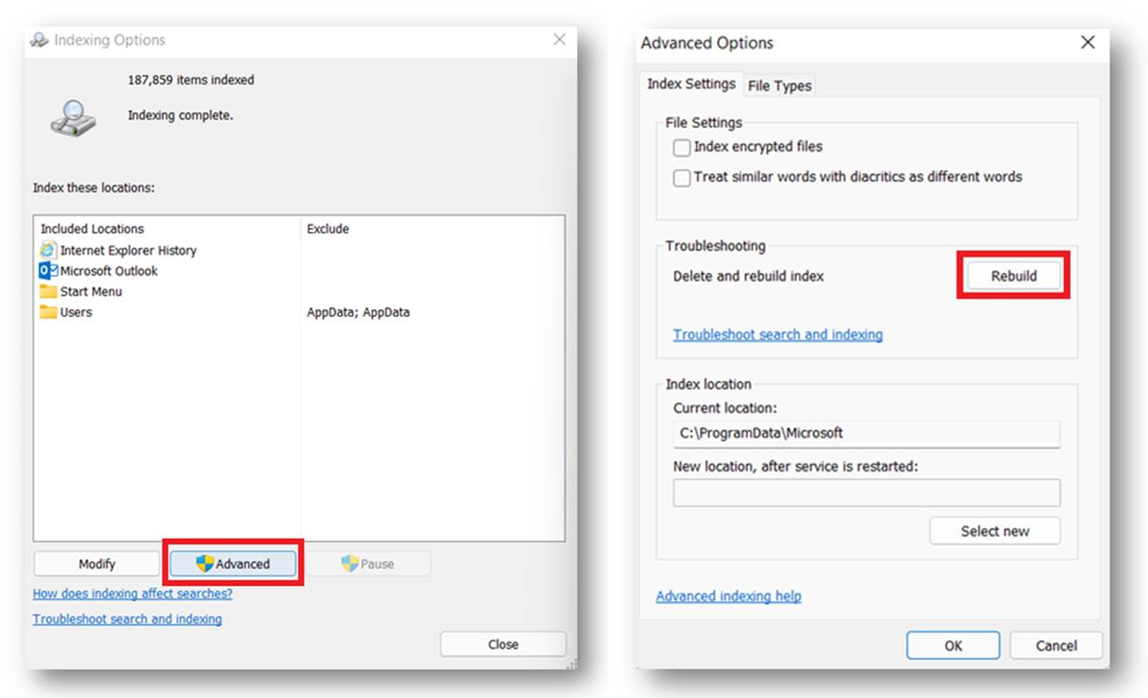
Please reference following steps to collect log and view in Windows Performance Analyzer (WPA):
- Settings -> Searching Windows -> Advanced Search Indexer Settings -> Advanced -> Delete and rebuild index (Rebuild)
- wpr -boottrace -addboot AcpiFanNoiseImpact.wprp –filemode
- Restart the system
- Check Index status of Settings -> Searching Windows (make sure device connect with AC-power source.)
- When index is completed, stop the trace: wpr -boottrace -stopboot AcpiFanNoiseImpact.etl (Cancel trace without saving: wpr -boottrace –cancel)
- Open AcpiFanNoiseImpact.etl via Windows Performance Analyzer (WPA).
Download the file at AcpiFanNoiseImpact.zip Or, copy the following and save as AcpiFanNoiseImpact.wprp
<?xml version="1.0" encoding="utf-8"?>
<WindowsPerformanceRecorder Version="1.0" Comments="Test" Company="Microsoft Corporation" Copyright="Microsoft Corporation">
    <Profiles>
        <!-- BufferSizes are in KB in WPRP -->
        <!-- System Collectors -->
        <SystemCollector Id="MySystemCollector" Name="NT Kernel Logger">
            <BufferSize Value="1024" />
            <Buffers Value="100" />
            <StackCaching BucketCount="2048" CacheSize="20480" />
            <FlushThreshold Value="70" />
        </SystemCollector>

        <!-- Event Collectors -->
        <EventCollector Id="MyEventCollector" Name="User Session Logger">
            <BufferSize Value="1024" />
            <Buffers Value="100" />
            <StackCaching BucketCount="2048" CacheSize="20480" />
            <FlushThreshold Value="70" />
        </EventCollector>

        <!-- System Providers for collecting kernel events. -->
        <SystemProvider Id="SP_AcpiFanNoiseImpactTrace">
            <Keywords Operation="Add">
                <Keyword Value="Loader" />
                <Keyword Value="Power" />
                <Keyword Value="ProcessThread" />
            </Keywords>
        </SystemProvider>
        <!-- System Providers for collecting kernel events. -->
        <!---->

        <EventProvider Id="EP_Microsoft-Windows-Kernel-Power" Name="Microsoft-Windows-Kernel-Power" Level="5" NonPagedMemory="true">
            <Keywords>
                <Keyword Value="0x2" />
            </Keywords>
            <CaptureStateOnStart>
                <Keyword Value="0x0" />
            </CaptureStateOnStart>
            <CaptureStateOnSave>
                <Keyword Value="0x0" />
            </CaptureStateOnSave>
        </EventProvider>
        <EventProvider Id="EP_Microsoft-Windows-Kernel-Acpi" Name="Microsoft-Windows-Kernel-Acpi" Level="5">
            <Keywords>
                <Keyword Value="0xffffffff" />
            </Keywords>
            <CaptureStateOnSave>
                <Keyword Value="0xffffffff" />
            </CaptureStateOnSave>
        </EventProvider>
        <EventProvider Id="CustomEventProvider_Microsoft.Windows.SRUM.Telemetry_TraceLogging" Name="7073707A-0587-4E03-B31F-6443EB1ACBCD" Level="5" />
        <EventProvider Id="CustomEventProvider_Microsoft.Windows.Kernel.Acpi_TraceLogging" Name="C42BBFDB-4140-4ada-81DF-2B9A18AC6A7B" Level="5" />
        <EventProvider Id="CustomEventProvider_Microsoft.Windows.Kernel.Power_TraceLogging" Name="63bca7a1-77ec-4ea7-95d0-98d3f0c0ebf7" Level="5" />
        <EventProvider Id="CustomEventProvider_AcpiTraceGuid_WPP" Name="03906A40-CCE8-447F-83F4-E2346215DB84" Level="7" />
        <EventProvider Id="CustomEventProvider_Microsoft.Windows.CentralResourceManager_TraceLogging" Name="8215e965-d26e-548e-af0e-940c1f06f250" Level="5" NonPagedMemory="true">
            <CaptureStateOnSave>
                <Keyword Value="0xFFFFFFFFFFFFFFFF" />
            </CaptureStateOnSave>
        </EventProvider>

        <Profile Id="PowerTrace.Verbose.File" LoggingMode="File" Name="PowerTrace" DetailLevel="Verbose" Description="Power trace logging">
            <Collectors>
                <SystemCollectorId Value="MySystemCollector">
                    <SystemProviderId Value="SP_AcpiFanNoiseImpactTrace" />
                </SystemCollectorId>
                <EventCollectorId Value="MyEventCollector">
                    <EventProviders>
                        <EventProviderId Value="EP_Microsoft-Windows-Kernel-Power" />
                        <EventProviderId Value="EP_Microsoft-Windows-Kernel-Acpi" />
                        <EventProviderId Value="CustomEventProvider_Microsoft.Windows.Kernel.Acpi_TraceLogging" />
                        <EventProviderId Value="CustomEventProvider_AcpiTraceGuid_WPP" />
                        <EventProviderId Value="CustomEventProvider_Microsoft.Windows.Kernel.Power_TraceLogging" />
                        <EventProviderId Value="CustomEventProvider_Microsoft.Windows.SRUM.Telemetry_TraceLogging" />
                        <EventProviderId Value="CustomEventProvider_Microsoft.Windows.CentralResourceManager_TraceLogging" />
                    </EventProviders>
                </EventCollectorId>
            </Collectors>
        </Profile>
    </Profiles>
    <TraceMergeProperties>
        <TraceMergeProperty Id="TraceMerge_Default" Name="TraceMerge_Default" Base="">
            <DeletePreMergedTraceFiles Value="true" />
            <FileCompression Value="true" />
            <CustomEvents>
                <CustomEvent Value="ImageId" />
                <CustomEvent Value="BuildInfo" />
                <CustomEvent Value="VolumeMapping" />
                <CustomEvent Value="EventMetadata" />
                <CustomEvent Value="PerfTrackMetadata" />
                <CustomEvent Value="WinSAT" />
                <CustomEvent Value="NetworkInterface" />
            </CustomEvents>
        </TraceMergeProperty>
    </TraceMergeProperties>
</WindowsPerformanceRecorder>
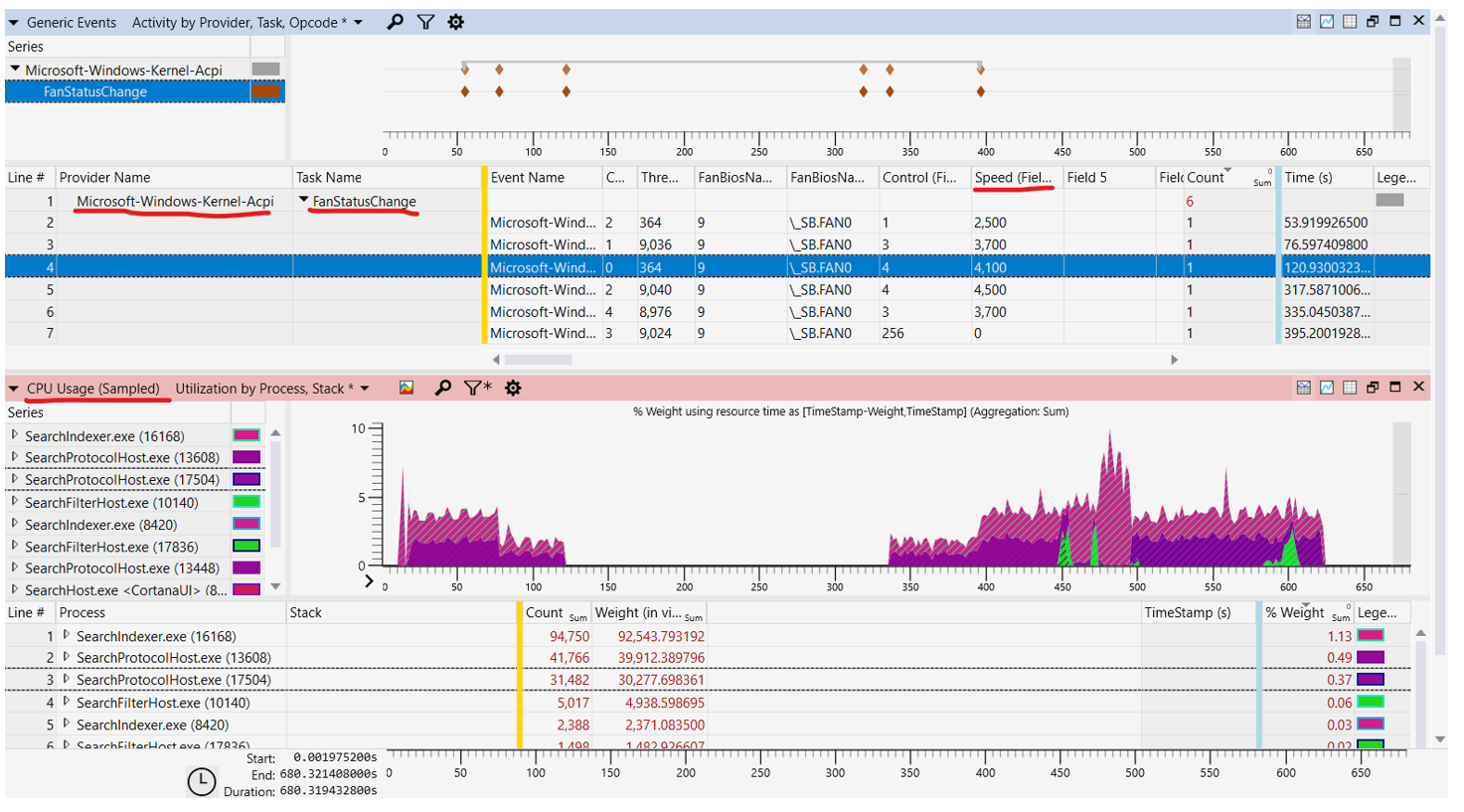
The image below is an example WPA graph showing Search Indexer work backing off when the fan is loud.
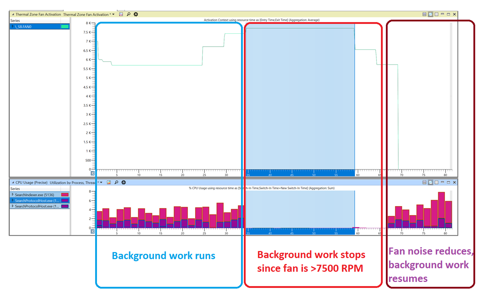
There is one level of the fan that would make search index back off in full (the highest, that should be impact score 4), but all other levels of the fan should be reduced activity and not suspension. For example, if ACPI declared Impact3MaxRPM = 4000 RPM in function 3 (Get fan operating ranges function), when Fan RPM > 4000 (4100RPM, 4500RPM), we would see SearchIndexer.exe and SearchProtocalHost.exe CPU Usage would be suspended.
Note
To see CPU Usage, you can use wpr -start power -filemode to collect runtime usage. Use wpr -stop fan_noise.etl to stop collecting log.
The image below shows an example WPA graph showing the suspension of SearchIndexer.exe and SearchProtocolHost