הערה
הגישה לדף זה מחייבת הרשאה. באפשרותך לנסות להיכנס או לשנות מדריכי כתובות.
הגישה לדף זה מחייבת הרשאה. באפשרותך לנסות לשנות מדריכי כתובות.
Note
This feature is currently in public preview. This preview is provided without a service-level agreement, and isn't recommended for production workloads. Certain features might not be supported or might have constrained capabilities. For more information, see Supplemental Terms of Use for Microsoft Azure Previews.
In the previous tutorial steps, each source table mapped to exactly one node type or one edge type. However, relational tables often contain embedded entities. For example, the Employees table includes a Country column. Rather than storing the country as just a property on Employee nodes, you can extract it into its own Country node type and connect it with a livesIn edge. This approach creates a richer graph model that lets you query relationships between employees and countries directly.
In this tutorial step, you create the following graph entities from the Employees mapping table:
- A
Countrynode type (new) - A
livesInedge type connectingEmployeetoCountry(new) - Modifications to the existing
Employeenode type to remove redundant properties
Employee --livesIn--> Country
Adventure Works Employee table
In the Adventure Works data model, the Employees data source table has the following columns:
EmployeeID_KManagerIDEmployeeFullNameJobTitleOrganizationLevelMaritalStatusGenderTerritoryCountryGroup
The following table shows how these columns map to graph entities:
| Graph entity | Type | Key column |
|---|---|---|
Employee |
Node (already exists) | EmployeeID_K |
Country |
Node (new) | Country |
livesIn |
Edge (new), from Employee to Country |
EmployeeID_K → Country |
Note
In the preceding table, Country refers to both the source column in the Employees table and the new node type in the graph. They share the same name, but the column is raw data in the table while the node type is an entity in your graph model.
When you create a node type from a mapping table, each column in the table becomes a property on that node type by default. Since the Employees table has 10 columns, both the Employee and Country node types initially get all 10 columns as properties. In the following steps, you remove properties that aren't relevant to each node type.
Create a Country node type
To create the Country node type, follow these steps:
In your graph model, select Add node.
In the Add node to graph dialog, enter the following values:
- Label:
Country - Mapping table: adventureworks_employees
- ID of the mapping column:
Country
- Label:
Select Confirm to add the node type to your graph.
Double-click the
Countrynode type to view its properties.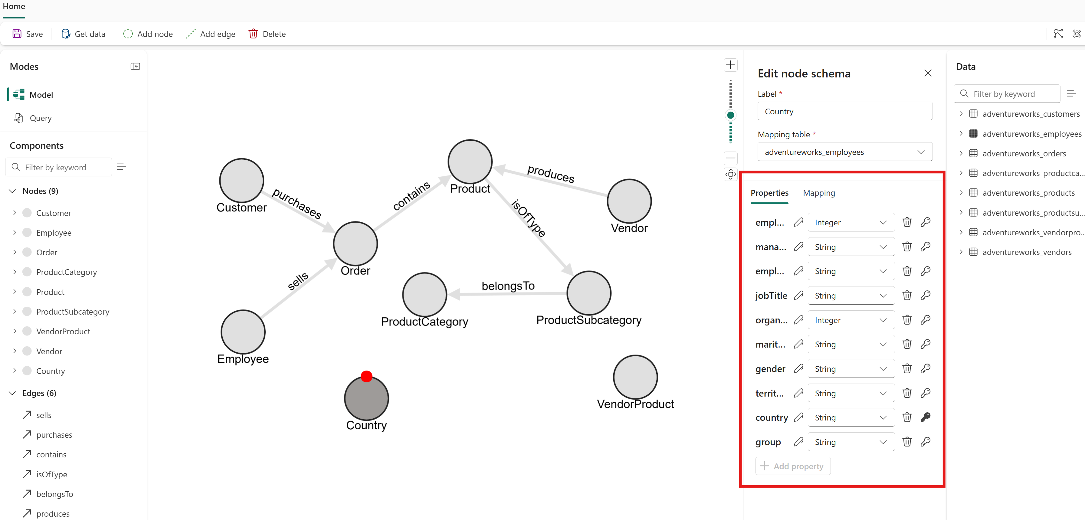
All 10 columns from the Employees table become properties by default. Delete the ones that aren't relevant to a country. Specifically, remove
EmployeeID_K,ManagerID,EmployeeFullName,JobTitle,OrganizationLevel,MaritalStatus,Gender,Territory, andGroup. Only theCountryproperty should remain.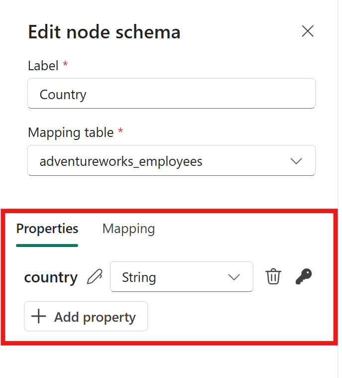


Modify the Employee node type
You created the Employee node type in a previous tutorial step. Now that Country is its own node type connected by the livesIn edge, the Country column is redundant as an Employee property.
- Double-click the
Employeenode type to view its properties. - Remove
Territory,Country, andGroupif you don't need them for your queries or analyses.
Tip
Excessive properties make your graph harder to maintain and use. For all node types, remove properties that are:
- Not required for the uniqueness of the nodes
- Not necessary for your queries or analyses
Create a livesIn edge
To create the livesIn edge type, follow these steps:
- Select Add edge.
- In the Add edge dialog, enter the following values:
- Label:
livesIn - Mapping table: adventureworks_employees
- Source node:
Employee - Mapping table column to be linked to source node key:
EmployeeID_K - Target node:
Country - Mapping table column to be linked to target node key:
Country
- Label:
- Select Confirm to add the edge to your graph.
Load the graph
After you configure all node types and edge types, load the graph:
- Select Save to verify the graph model, load data from OneLake, construct the graph, and make it ready for querying. Be patient, as this process might take some time depending on the size of your data.

The graph now includes the new Country node type and livesIn edge type. You can query relationships between employees and their countries directly.
Recap
In this tutorial step, you derived two node types and one edge type from the single Employees mapping table:
Employeenode (created in a previous step, refined here)Countrynode (new, extracted from theCountrycolumn)livesInedge (new, connectingEmployee→Country)
This pattern is useful whenever a relational table contains embedded entities that you want to represent as separate nodes in your graph. Look for columns that represent distinct real-world entities, such as countries, cities, or departments, as candidates for extraction into their own node types.