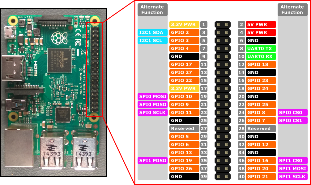
Raspberry Pi 2 と Raspberry Pi 3 のハードウェア インターフェイスは、ボード上の 40 ピン ヘッダー J8 を介して公開されます。 以下の機能があります。
- 24x - GPIO ピン
- 1x - シリアル UART (RPi3 にはミニ UART のみを含む)
- 2x - SPI バス
- 1x - I2C バス
- 2x - 5V 電源ピン
- 2x - 3.3V 電源ピン
- 8x - グラウンド ピン
GPIO ピン
このデバイスで使用できる GPIO を見てみしましょう。
GPIO ピンの概要
次の GPIO ピンは、API でアクセスできます。
GPIO# 電源オン時のプル 代替関数 ヘッダー ピン 2 PullUp I2C1 SDA 3 3 PullUp I2C1 SCL 5 4 PullUp 7 5 PullUp 29 6 PullUp 31 7 PullUp SPI0 CS1 26 8 PullUp SPI0 CS0 24 9 PullDown SPI0 MISO 21 10 PullDown SPI0 MOSI 19 11 PullDown SPI0 SCLK 23 12 PullDown 32 13 PullDown 33 16 PullDown SPI1 CS0 36 17 PullDown 11 18 PullDown 12 19 PullDown SPI1 MISO 35 20 PullDown SPI1 MOSI 38 21 PullDown SPI1 SCLK 40 22 PullDown 15 23 PullDown 16 24 PullDown 18 25 PullDown 22 26 PullDown 37 27 PullDown 13 35* PullUp 赤色の電源 LED 47* PullUp 緑色のアクティビティ LED
* = Raspberry Pi 2 のみ。 GPIO 35 および 47 は Raspberry Pi 3 では使用できません。
GPIO サンプル
たとえば、次のコードでは、GPIO 5 を出力として開き、デジタルの「1」をピンに書き出します。
using Windows.Devices.Gpio;

public void GPIO()
{
    // Get the default GPIO controller on the system
    GpioController gpio = GpioController.GetDefault();
    if (gpio == null)
        return; // GPIO not available on this system

    // Open GPIO 5
    using (GpioPin pin = gpio.OpenPin(5))
    {
        // Latch HIGH value first. This ensures a default value when the pin is set as output
        pin.Write(GpioPinValue.High);

        // Set the IO direction as output
        pin.SetDriveMode(GpioPinDriveMode.Output);

    } // Close pin - will revert to its power-on state
}
ピンを開くと、そのピンは電源オン状態になります。これには、プル抵抗が含まれる場合があります。 プル抵抗を切断し、高インピーダンス入力を取得するには、ドライブ モードを GpioPinDriveMode .Input に設定します。
pin.SetDriveMode(GpioPinDriveMode.Input);
ピンを閉じると、電源オン状態に戻ります。
ピンの多重化
一部の GPIO ピンでは、複数の機能を実行できます。 既定では、ピンは GPIO 入力として構成されます。 I2cDevice.FromIdAsync()またはSpiDevice.FromIdAsync()を呼び出して代替関数を開くと、関数に必要なピンが自動的に適切な関数に切り替わるようになります (「多重化」)。 I2cDevice.Dispose()またはSpiDevice.Dispose()を呼び出すことによってデバイスを閉じると、ピンが既定の機能に戻ります。 2 つの異なる関数に対して同時にピンを使用しようとすると、競合している関数を開こうとしたときに例外が発生します。 たとえば、 にします。
var controller = GpioController.GetDefault();
var gpio2 = controller.OpenPin(2);      // open GPIO2, shared with I2C1 SDA

var dis = await DeviceInformation.FindAllAsync(I2cDevice.GetDeviceSelector());
var i2cDevice = await I2cDevice.FromIdAsync(dis[0].Id, new I2cConnectionSettings(0x55)); // exception thrown because GPIO2 is open

gpio2.Dispose(); // close GPIO2
var i2cDevice = await I2cDevice.FromIdAsync(dis[0].Id, new I2cConnectionSettings(0x55)); // succeeds because gpio2 is now available

var gpio2 = controller.OpenPin(2); // throws exception because GPIO2 is in use as SDA1

i2cDevice.Dispose(); // release I2C device
var gpio2 = controller.OpenPin(2); // succeeds now that GPIO2 is available
シリアル UART
RPi2/3 で使用可能なシリアル UART が 1 つあります: UART0
- Pin 8 - UART0 TX
- Pin 10 - UART0 RX
次の例では、UART0 を初期化し、書き込みの後に読み取りを実行します。
using Windows.Storage.Streams;
using Windows.Devices.Enumeration;
using Windows.Devices.SerialCommunication;

public async void Serial()
{
    string aqs = SerialDevice.GetDeviceSelector("UART0");                   /* Find the selector string for the serial device   */
    var dis = await DeviceInformation.FindAllAsync(aqs);                    /* Find the serial device with our selector string  */
    SerialDevice SerialPort = await SerialDevice.FromIdAsync(dis[0].Id);    /* Create an serial device with our selected device */

    /* Configure serial settings */
    SerialPort.WriteTimeout = TimeSpan.FromMilliseconds(1000);
    SerialPort.ReadTimeout = TimeSpan.FromMilliseconds(1000);
    SerialPort.BaudRate = 9600;                                             /* mini UART: only standard baud rates */
    SerialPort.Parity = SerialParity.None;                                  /* mini UART: no parities */
    SerialPort.StopBits = SerialStopBitCount.One;                           /* mini UART: 1 stop bit */
    SerialPort.DataBits = 8;

    /* Write a string out over serial */
    string txBuffer = "Hello Serial";
    DataWriter dataWriter = new DataWriter();
    dataWriter.WriteString(txBuffer);
    uint bytesWritten = await SerialPort.OutputStream.WriteAsync(dataWriter.DetachBuffer());

    /* Read data in from the serial port */
    const uint maxReadLength = 1024;
    DataReader dataReader = new DataReader(SerialPort.InputStream);
    uint bytesToRead = await dataReader.LoadAsync(maxReadLength);
    string rxBuffer = dataReader.ReadString(bytesToRead);
}
シリアル UART コードを実行するには、UWP プロジェクトの Package.appxmanifest ファイルに次の機能を追加する必要があるので注意してください。
Visual Studio 2017 のマニフェスト デザイナーには、シリアル通信機能に影響する (appxmanifest ファイルのビジュアル エディター) 既知のバグがあります。 appxmanifest によってシリアル通信機能が追加された場合、デザイナーを使用して appxmanifest を変更すると、appxmanifest が破損します (デバイス xml の子が失われます)。 この問題を回避するには、appxmanifest を右クリックし、コンテキスト メニューから [コードの表示] を選択して、appxmanifest を手動で編集します。
  <Capabilities>
    <DeviceCapability Name="serialcommunication">
      <Device Id="any">
        <Function Type="name:serialPort" />
      </Device>
    </DeviceCapability>
  </Capabilities>
I2C バス
このデバイスで使用できる I2C バスを見てみしましょう。
I2C の概要
2 行の SDA と SCL で ピン ヘッダーに公開されている I2C コントローラー I2C1 が 1 つあります。 このバスのボードには、1.8 KΩ 内部プルアップ抵抗が既にインストールされています。
シグナル名 ヘッダーのピン番号 GPIO 番号 SDA 3 2 SCL 5 3
次の例では、I2C1 を初期化し、アドレスが 0x40 である I2C デバイスにデータを書き込みます。
using Windows.Devices.Enumeration;
using Windows.Devices.I2c;

public async void I2C()
{
    // 0x40 is the I2C device address
    var settings = new I2cConnectionSettings(0x40);
    // FastMode = 400KHz
    settings.BusSpeed = I2cBusSpeed.FastMode;

    // Create an I2cDevice with the specified I2C settings
    var controller = await I2cController.GetDefaultAsync();

    using (I2cDevice device = controller.GetDevice(settings))
    {
        byte[] writeBuf = { 0x01, 0x02, 0x03, 0x04 };
        device.Write(writeBuf);
    }
}
SPI バス
RPi2/3 で利用できる SPI バス コントローラーが 2 つあります。
SPI0
シグナル名 ヘッダーのピン番号 GPIO 番号 MOSI 19 10 MISO 21 9 SCLK 23 11 CS0 24 8 CS1 26 7
SPI1
シグナル名 ヘッダーのピン番号 GPIO 番号 MOSI 38 20 MISO 35 19 SCLK 40 21 CS0 36 16
SPI サンプル
チップ選択 0 を使用してバス SPI0 で SPI 書き込みを実行する方法の例を次に示します。
using Windows.Devices.Enumeration;
using Windows.Devices.Spi;

public async void SPI()
{
    // Use chip select line CS0
    var settings = new SpiConnectionSettings(0);
    // Set clock to 10MHz
    settings.ClockFrequency = 10000000;

    // Get a selector string that will return our wanted SPI controller
    string aqs = SpiDevice.GetDeviceSelector("SPI0");

    // Find the SPI bus controller devices with our selector string
    var dis = await DeviceInformation.FindAllAsync(aqs);

    // Create an SpiDevice with our selected bus controller and Spi settings
    using (SpiDevice device = await SpiDevice.FromIdAsync(dis[0].Id, settings))
    {
        byte[] writeBuf = { 0x01, 0x02, 0x03, 0x04 };
        device.Write(writeBuf);
    }
}