HoloLens (第 1 世代) と Azure 310: 物体検出
Note
Mixed Reality Academy のチュートリアルは、HoloLens (第 1 世代) と Mixed Reality イマーシブ ヘッドセットを念頭に置いて編成されています。 そのため、それらのデバイスの開発に関するガイダンスを引き続き探している開発者のために、これらのチュートリアルをそのまま残しておくことが重要だと考えています。 これらのチュートリアルが、HoloLens 2 に使用されている最新のツールセットや操作に更新されることは "ありません"。 これらは、サポートされているデバイス上で継続して動作するように、保守されます。 今後、HoloLens 2 の開発方法を説明する新しいチュートリアルが公開される予定です。 この通知は、それらのチュートリアルが投稿されたときにリンクと共に更新されます。
このコースでは、複合現実アプリケーションで Azure Custom Vision の "物体検出" 機能を使用して、提供された画像内のカスタム ビジュアル コンテンツとその空間位置を認識する方法について説明します。
このサービスでは、オブジェクトの画像を使用して機械学習モデルをトレーニングできます。 その後、トレーニング済みのモデルを使用して、現実世界にある類似する物体を認識し、それらの位置を概算します。これらの物体は、Microsoft HoloLens のカメラ キャプチャまたは PC に接続されたイマーシブ (VR) ヘッドセット用のカメラによって提供されます。
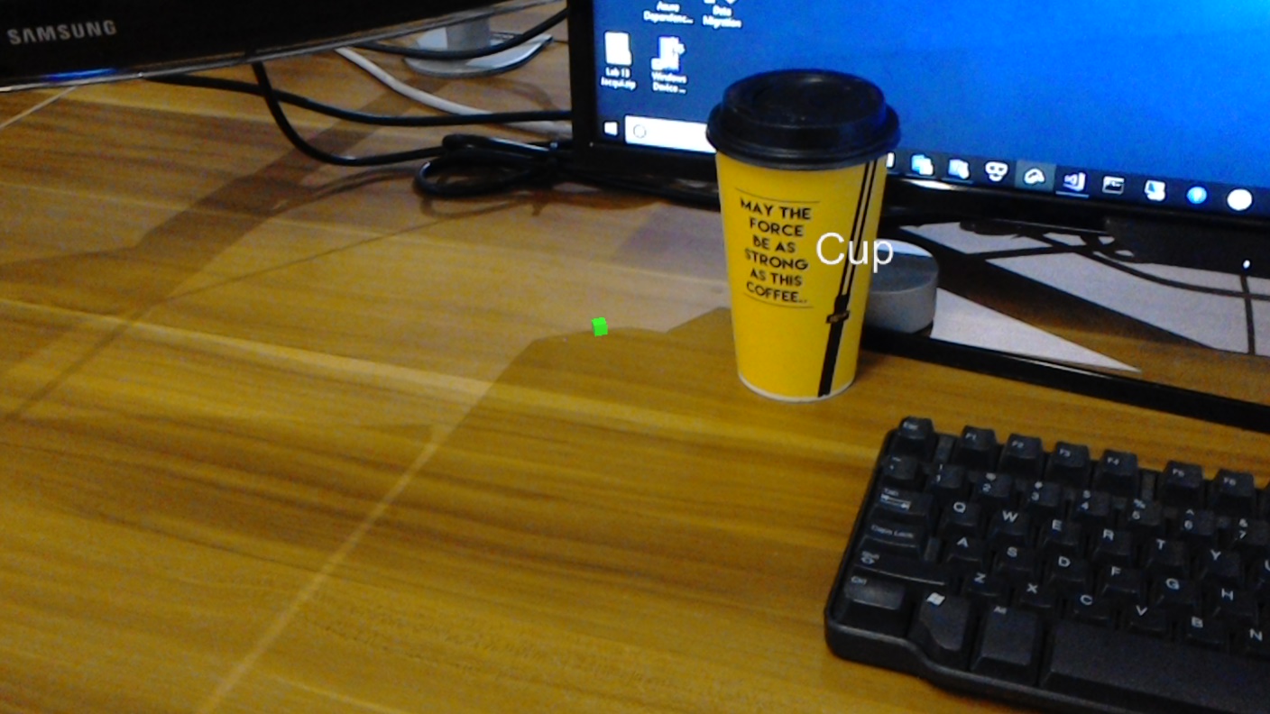
Azure Custom Vision の物体検出は、Microsoft サービスの 1 つで、開発者はこれを使用してカスタム画像分類器を構築できます。 これらの分類器を新しい画像に対して使用すると、画像自体内に四角形の境界線が表示されて、その新しい画像内で物体が検出されます。 このプロセスを効率化するため、このサービスにはシンプルで使いやすいオンライン ポータルが用意されています。 詳しくは、次のリンクを参照してください。
このコースを完了すると、次の処理を実行できる複合現実アプリケーションが完成します。
- ユーザーは、物体を "視線入力" できます。これは、Azure Custom Vision サービスの物体検出を使用してトレーニングしたものです。
- ユーザーは、"タップ" ジェスチャを使用して、見ているものの画像をキャプチャします。
- この画像は、アプリにより Azure Custom Vision サービスに送信されます。
- サービスから応答があり、認識の結果がワールド空間テキストとして表示されます。 これは、Microsoft HoloLens の空間追跡を認識された物体の実世界での位置を把握する方法として使用し、さらに、ラベル テキストを提供するために、画像で検出されたものに関連付けられる "タグ" を使用して実行されます。
また、このコースでは、手動で画像をアップロードする方法、タグを作成する方法についても説明し、さらに、送信する画像内に "境界ボックス" を設定することで、さまざまな物体 (提供されている例では、カップ) を認識するようにサービスをトレーニングする方法についても説明します。
重要
開発者は、アプリを作成して使用した後、Azure Custom Vision サービスに戻り、サービスによって行われた予測を確認し、それらの予測が正しいかどうかを判定する必要があります (このために、サービスが誤ったものにはタグを付け、"境界ボックス" を調整します)。 その後、サービスを再トレーニングできます。これにより、現実世界の物体を認識する精度が上がります。
このコースでは、Azure Custom Vision サービスの物体検出から結果を取得して、Unity ベースのサンプル アプリケーションに取り込む方法について説明します。 作成中のカスタム アプリケーションがある場合に、これらの概念をそのアプリケーションで採用するかどうかはご自身でご判断ください。
デバイス サポート
| コース | HoloLens | イマーシブ ヘッドセット |
|---|---|---|
| MR と Azure 310: オブジェクト検出 | ✔️ |
前提条件
Note
このチュートリアルは、Unity と C# の基本的な使用経験がある開発者を対象としています。 また、このドキュメント内の前提条件や文章による説明は、執筆時 (2018 年 7 月) にテストおよび検証された内容であることをご了承ください。 ツールのインストールの記事に記載されているように、お客様は最新のソフトウェアを自由に使用できます。ただし、このコースの情報は、以下に記載されているものよりも新しいソフトウェアでの設定や結果と完全に一致するとは限りません。
このコースでは、次のハードウェアとソフトウェアをお勧めします。
- 開発用 PC
- 開発者モードが有効になっている Windows 10 Fall Creators Update (またはそれ以降)
- 最新の Windows 10 SDK
- Unity 2017.4 LTS
- Visual Studio 2017
- 開発者モードが有効になっている Microsoft HoloLens
- Azure のセットアップと Custom Vision サービスの取得のためのインターネット アクセス
- Custom Vision に認識させる各物体の一連の画像が少なくとも 15 枚は必要です。 必要な場合は、このコースで事前に用意されている画像 (一連のカップ) を使用できます。
開始する前に
- このプロジェクトをビルドする際の問題を避けるために、このチュートリアルで紹介するプロジェクトをルートまたはルートに近いフォルダーに作成することを強くお勧めします (フォルダー パスが長いと、ビルド時に問題が発生する可能性があります)。
- HoloLens を設定してテストします。 このためのサポートが必要な場合は、HoloLens の設定に関する記事を参照してください。
- 新しい HoloLens アプリの開発を開始するときは、調整とセンサーのチューニングを実行することをお勧めします (ユーザーごとにこれらのタスクを実行すると役立つ場合があります)。
調整の詳細については、この HoloLens の調整に関する記事へのリンクを参照してください。
センサー チューニングの詳細については、この HoloLens センサー チューニングに関する記事へのリンクを参照してください。
第 1 章 - Custom Vision ポータル
Azure Custom Vision サービスを使用するには、アプリケーションで使用できるようにそのインスタンスを構成する必要があります。
Custom Vision サービスのメイン ページに移動します。
[Getting Started]\(作業の開始\) をクリックします。
![[はじめに] ボタンが強調表示されているスクリーンショット。](images/azurelabs-lab310-01.png)
Custom Vision ポータルにサインインします。
![[サインイン] ボタンを示すスクリーンショット。](images/azurelabs-lab310-02.png)
まだ Azure アカウントをお持ちでない方は、作成する必要があります。 このチュートリアルを教室やラボで受講している場合は、インストラクターや監督者に新しいアカウントの設定方法を質問してください。
初めてログインすると、[サービス利用規約] パネルが表示されます。 "利用規約に同意" するためにチェック ボックスをオンします。 次に、[同意する] をクリックします。
![[サービス条件] パネルを示すスクリーンショット。](images/azurelabs-lab310-03.png)
利用規約に同意すると、[マイ プロジェクト] セクションが表示されます。 [新しいプロジェクト] をクリックします。
![[新しいプロジェクト] を選択する場所を示すスクリーンショット。](images/azurelabs-lab310-04.png)
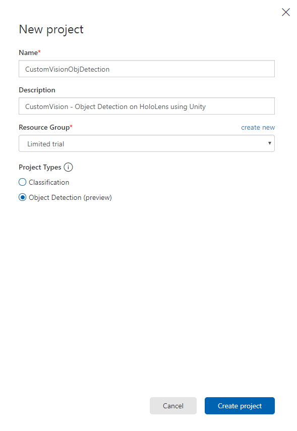
右側にタブが表示され、プロジェクトに関するいくつかのフィールドを指定するように求められます。
プロジェクトの名前を入力します。
プロジェクトの説明を入力します (省略可能)。
[リソース グループ] を選択するか、新規に作成します。 リソース グループは、Azure アセットのコレクションの監視、アクセス制御、プロビジョニング、課金管理を行う方法を提供します。 共通のリソース グループで、1 つのプロジェクト (たとえば、これらのコースなど) に関連するすべての Azure サービスを保持することをお勧めします。
Note
Azure リソース グループについて詳しくは、関連するドキュメントを参照してください
[プロジェクトの種類] として [物体検出 (プレビュー)] を設定します。
完了したら、[プロジェクトの作成] をクリックします。Custom Vision サービスのプロジェクト ページにリダイレクトされます。
第 2 章 - Custom Vision プロジェクトをトレーニングする
Custom Vision ポータルにアクセスする主な目的は、画像内の特定の物体を認識するようにプロジェクトをトレーニングすることです。
アプリケーションで認識する各物体の画像が少なくとも 15 枚は必要です。 このコースで用意されている画像 (一連のカップ) を使用できます。
Custom Vision プロジェクトをトレーニングするには、次の手順を実行します。
[タグ] の横にある + ボタンをクリックします。
![[タグ] の横にある [+] ボタンを示すスクリーンショット。](images/azurelabs-lab310-06.png)
画像を関連付けるために使用されるタグの名前を追加します。 この例では、認識用にカップの画像を使用するため、タグにはこの「Cup」という名前を付けました。 完了したら、[保存] をクリックします。
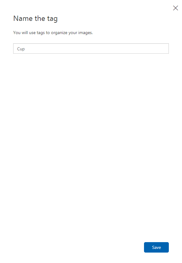
タグが追加されていることがわかります (タグを表示するために、ページの再読み込みが必要になる場合があります)。
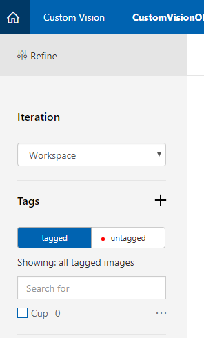
ページの中央にある [画像の追加] をクリックします。
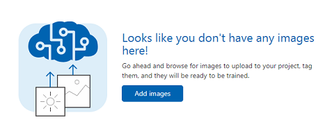
[ローカル ファイルの参照] をクリックし、アップロードする特定の物体を示す画像を参照します。少なくとも 15 枚アップロードします。
ヒント
一度に複数の画像を選択してアップロードできます。
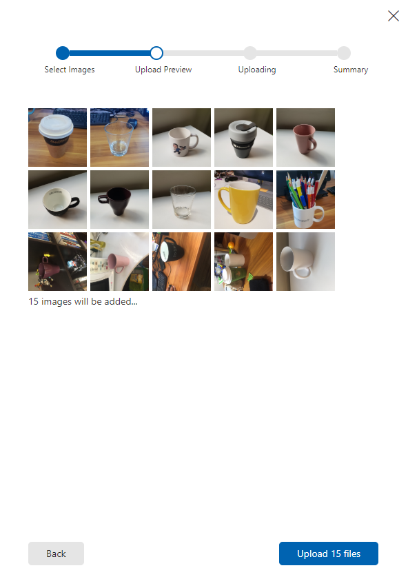
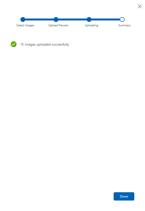
プロジェクトをトレーニングするために使用するすべての画像を選択した後、[ファイルのアップロード] を押します。 ファイルのアップロードが開始されます。 アップロードの確認が完了したら、[完了] をクリックします。
この時点で、画像はアップロードされていますが、タグは付けられていません。
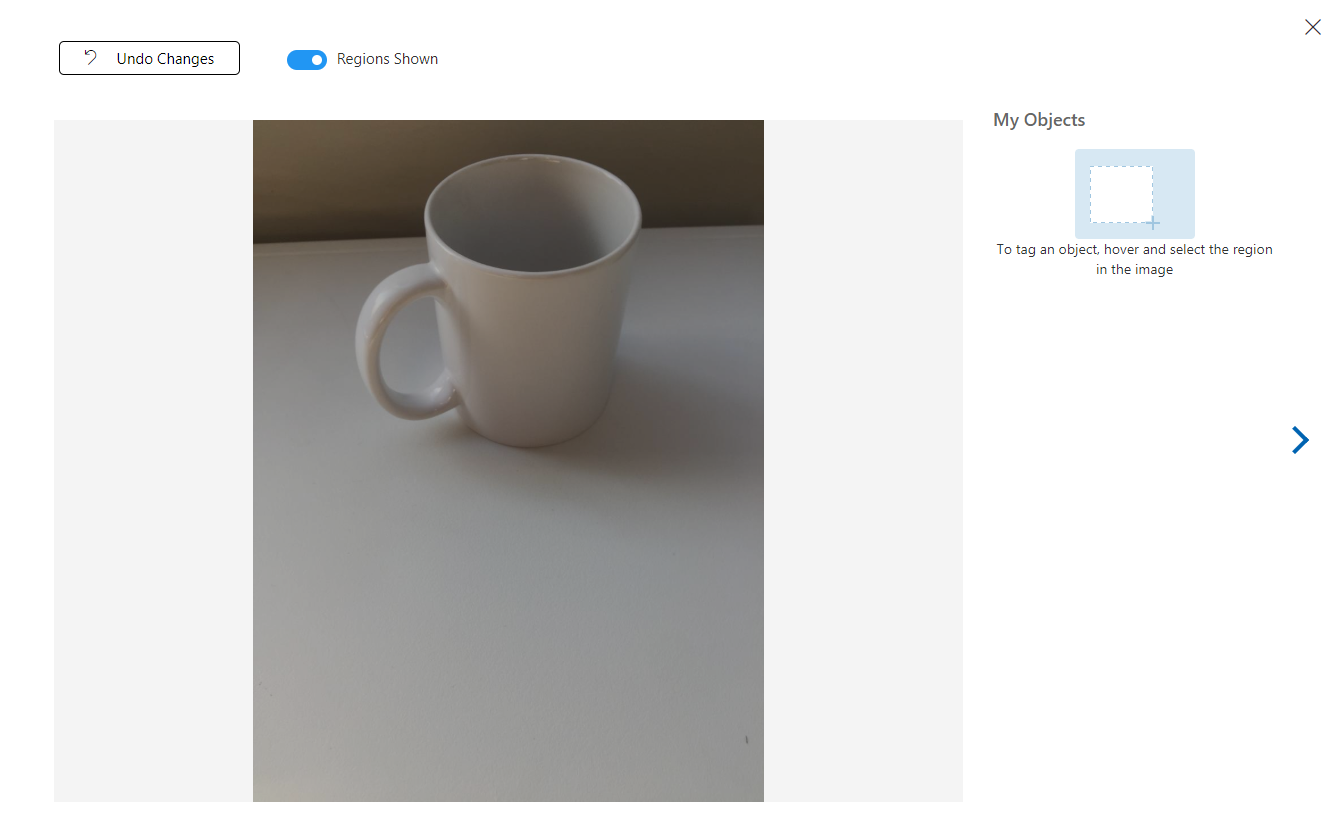
画像にタグを付けるには、マウスを使用します。 画像にマウス ポインターを合わせると、物体の周囲に選択範囲が自動的に描画され、選択内容が強調表示されます。 正確ではない場合、独自に描画できます。 これを行うには、マウスの左ボタンを押したままドラッグして、物体を囲むように選択領域を描画します。
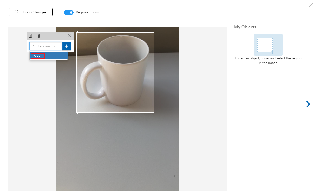
画像内で物体を選択すると、小さいプロンプトが表示され、"領域タグを追加" するように求められます。 事前に作成したタグ (上記の例では "Cup") を選択します。またタグを追加する場合は、そのタグを入力し、+ (正符号) ボタンをクリックします。
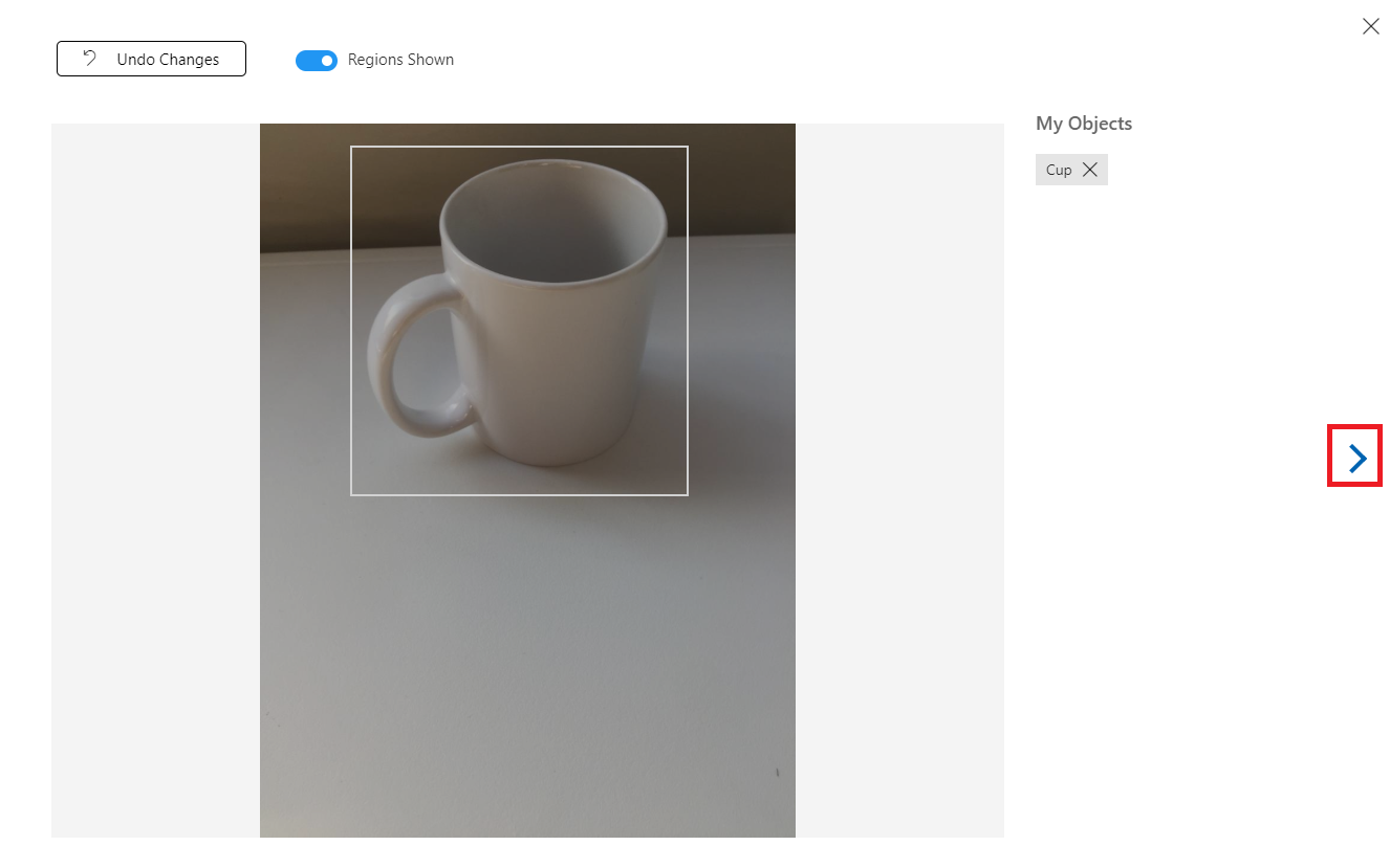
次の画像にタグを付けるために、ブレードの右側にある矢印をクリックします。または (ブレードの右上隅にある X をクリックして) タグ ブレードを閉じ、次の画像をクリックします。 次の画像の準備ができたら、同じ手順を繰り返します。 アップロードしたすべての画像に対してこれを行い、すべての画像にタグを付けます。
Note
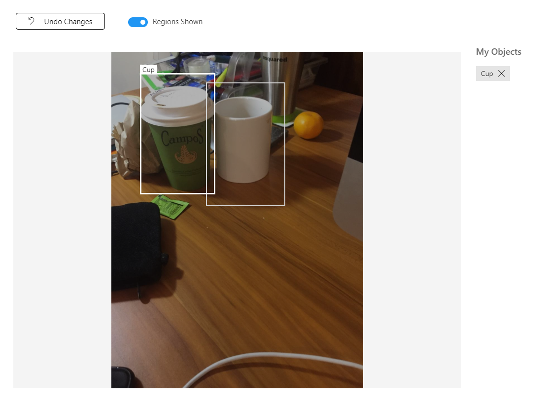
次の図のように、同じ画像内にある複数の物体を選択できます。
すべてにタグを付けた後、画面の左側にある [タグ付き] ボタンをクリックして、タグが付けられた画像を表示します。
![[タグ付け] ボタンが強調表示されているスクリーンショット。](images/azurelabs-lab310-16.png)
これで、サービスをトレーニングする準備ができました。 [トレーニング] ボタンをクリックします。最初のトレーニング イテレーションが開始されます。
![[トレーニング] ボタンが強調表示されているスクリーンショット。](images/azurelabs-lab310-17.png)

ビルドが完了すると、[既定値にする] と [予測 URL] という 2 つのボタンが表示されます。 最初に [既定値にする] をクリックし、次に [予測 URL] をクリックします。
![[既定にする] ボタンが強調表示されているスクリーンショット。](images/azurelabs-lab310-19.png)
Note
これによって提供されるエンドポイントは、既定としてマークされている "イテレーション" に設定されます。 そのため、後で新しいイテレーションを作成し、それを既定として更新する場合は、コードを変更する必要はありません。
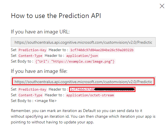
[予測 URL] をクリックした後、"メモ帳" を開き、URL (別名: 予測エンドポイント) とサービス予測キーをコピーして貼り付けます。これは、これらが後でコードで必要になったときに使用できるようにするためです。
第 3 章 - Unity プロジェクトの設定
次の設定は、複合現実での開発のための一般的な設定であるため、他のプロジェクトのテンプレートとして利用できます。
Unity を開き、[新規] をクリックします。
![[新規] ボタンが強調表示されているスクリーンショット。](images/azurelabs-lab310-21.png)
次に Unity のプロジェクト名を指定する必要があります。 CustomVisionObjDetection と入力します。 プロジェクトの種類が [3D] に設定されていることを確認し、[場所] を適切な場所に設定します (ルート ディレクトリに近い場所が適しています)。 [Create project]\(プロジェクトの作成\) をクリックします。
![プロジェクトの詳細と [プロジェクトの作成] を選択する場所を示すスクリーンショット。](images/azurelabs-lab310-22.png)
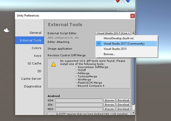
Unity を開いた状態で、既定のスクリプト エディターが Visual Studio に設定されているかどうか確認することをお勧めします。 [編集] > [環境設定] に移動し、新しいウィンドウで [外部ツール] に移動します。 [外部スクリプト エディター] を [Visual Studio] に変更します。 [環境設定] ウィンドウを閉じます。
次に、[ファイル] > [ビルド設定] に移動し、[プラットフォーム] を [ユニバーサル Windows プラットフォーム] に切り替え、[プラットフォームの切り替え] ボタンをクリックします。
![[プラットフォームの切り替え] ボタンが強調表示されているスクリーンショット。](images/azurelabs-lab310-24.png)
同じ [ビルド設定] ウィンドウで、次のように設定されていることを確認します。
[ターゲット デバイス] が [HoloLens] に設定されている
[Build Type] (ビルドの種類) が [D3D] に設定されている
[SDK] が [最新のインストール] に設定されている。
[Visual Studio Version] (Visual Studio のバージョン) が [Latest installed] (最新のインストール) に設定されている
[Build and Run] (ビルドと実行) が [Local Machine] (ローカル マシン) に設定されている
[ビルド設定] の残りの設定は、ここでは既定値のままにしておきます。
![[ビルド設定] 構成オプションを示すスクリーンショット。](images/azurelabs-lab310-25.png)
同じ [ビルド設定] ウィンドウで、[プレーヤー設定] ボタンをクリックすると、[インスペクター] が配置されているスペースに関連パネルが表示されます。
このパネルでは、いくつかの設定を確認する必要があります。
[Other Settings] (その他の設定) タブで、次の内容を確認します。
[スクリプト ランタイム バージョン] が [試験段階 (.NET 4.6 と同等)] である (この場合、エディターの再起動が必要になります)。
[スクリプト バックエンド] が [.NET] である。
[API 互換性レベル] が [.NET 4.6] である。
![.NET 4.6 に設定された [API 互換性レベル] オプションを示すスクリーンショット。](images/azurelabs-lab310-26.png)
[Publishing Settings]\(公開設定\) タブ内の [Capabilities]\(機能\) で、次の内容を確認します。
InternetClient
Web カメラ
SpatialPerception
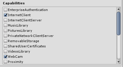
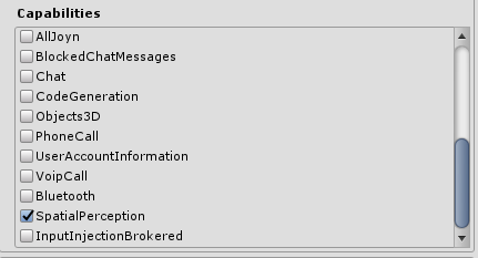
さらに、パネルの下にある ([公開設定] の下の) [XR 設定] で、[Virtual Reality サポート] をオンにして、Windows Mixed Reality SDK が追加されるようにします。
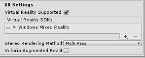
[ビルド設定] に戻ると、"Unity C# プロジェクト" に適用されていた灰色表示が解除されています。その横にあるチェック ボックスをオンにします。
[ビルド設定] ウィンドウを閉じます。
エディターで、[編集] > [プロジェクト設定] > [グラフィックス] をクリックします。
![[グラフィックス] メニュー オプションが選択されていることを示すスクリーンショット。](images/azurelabs-lab310-30.png)
[インスペクター] パネルで、[グラフィック設定] が開きます。 [常にシェーダーを含める] という配列が表示されるまで下にスクロールします。 [サイズ] 変数を 1 増やしてスロットを追加します (この例では、8 から 9 に増やしました)。 次に示すように、配列の最後の位置に新しいスロットが表示されます。
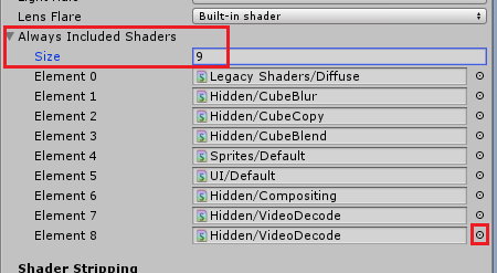
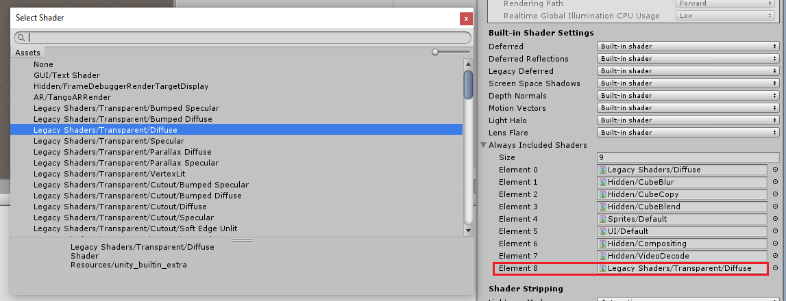
スロットで、スロットの横にある小さな的の形の円をクリックして、シェーダーの一覧を開きます。 [レガシ シェーダー/透過/拡散] シェーダーを見つけ、それをダブルクリックします。
第 4 章 - CustomVisionObjDetection Unity パッケージをインポートする
このコースでは、Azure-MR-310.unitypackage という Unity アセット パッケージが用意されています。
[ヒント] Unity でサポートされるオブジェクト (シーン全体を含む) は、.unitypackage ファイルにパッケージ化できます。このファイルをエクスポートして他のプロジェクトにインポートできます。 これが、異なる Unity プロジェクト間でアセットを移動する最も安全で最も効率的な方法です。
こちらに、ダウンロードする必要がある Azure-MR-310 パッケージがあります。
Unity のダッシュボードを表示して、画面上部のメニューにある [アセット] をクリックし、[パッケージのインポート] > [カスタム パッケージ] をクリックします。
![[カスタム パッケージ] メニュー オプションが強調表示されているスクリーンショット。](images/azurelabs-lab310-33.png)
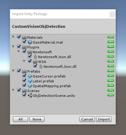
ファイル ピッカーを使用して Azure-MR-310.unitypackage パッケージを選択し、[開く] をクリックします。 このアセットのコンポーネントリストを表示します。 [インポート] ボタンをクリックしてインポートを実行します。
インポートが完了すると、パッケージのフォルダーが Assets フォルダーに追加されているのがわかります。 このようなフォルダー構造は、Unity プロジェクトの典型的なものです。
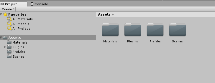
Materials フォルダーには、視線カーソルで使用される素材が含まれています。
Plugins フォルダーには、サービスの Web 応答を逆シリアル化するためにコードで使用される Newtonsoft DLL が含まれています。 Unity エディターと UWP ビルドの両方でライブラリを使用およびビルドできるようにするために、2 つの異なるバージョンをフォルダーとサブフォルダーに格納する必要があります。
Prefabs フォルダーには、シーンに含まれるプレハブが含まれています。 これらには次のようなものがあります。
- GazeCursor: アプリケーションで使用されるカーソル。 SpatialMapping プレハブと連動し、物理的物体の上のシーンに配置できます。
- Label: これは、必要に応じて、シーンに物体タグを表示するために使用される UI オブジェクトです。
- SpatialMapping: これは、アプリケーションで Microsoft HoloLens の空間追跡を使用して仮想マップを使用および作成できるようにするオブジェクトです。
Scenes フォルダーには、このコースのために事前に構築されたシーンが現在含まれています。
[プロジェクト] パネルで Scenes フォルダーを開き、ObjDetectionScene をダブルクリックして、このコースで使用するシーンを読み込みます。
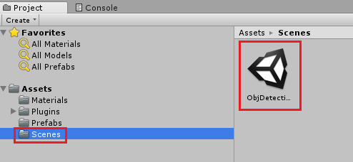
Note
コードは含まれていないため、このコースに従いコードを記述します。
第 5 章 - CustomVisionAnalyser クラスを作成する
この時点で、コードを記述する準備ができました。 最初に、CustomVisionAnalyser クラスを作成します。
Note
次に示すコードでは、Custom Vision REST API を使用して Custom Vision サービスを呼び出します。 これを使用して、この API を実装して使用する方法を確認します (自力で同様の機能を実装する方法を理解するのに役立ちます)。 Microsoft では、このサービスを呼び出すために使用できる Custom Vision SDK を提供しています。 詳細については、Custom Vision SDK に関する記事を参照してください。
このクラスでは次のことを行います。
キャプチャされた最新の画像をバイト配列として読み込みます。
分析のために Azure Custom Vision サービス インスタンスにバイト配列を送信します。
応答を JSON 文字列として受け取ります。
応答を逆シリアル化し、結果として得られる予測を応答の表示方法を制御する SceneOrganiser クラスに渡します。
このクラスを作成するには、次の手順を実行します。
[プロジェクト] パネルにある Asset フォルダーを右クリックし、[作成]>[フォルダー] をクリックします。 フォルダーに「Scripts」という名前を付けます。
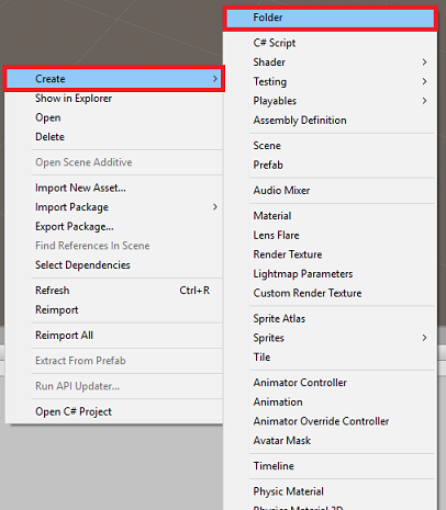
新しく作成したフォルダーをダブルクリックして開きます。
フォルダー内を右クリックし、[作成]>[C# スクリプト] をクリックします。 スクリプトに「CustomVisionAnalyser」という名前を付けます。
新しい CustomVisionAnalyser スクリプトをダブルクリックして Visual Studio で開きます。
ファイルの先頭部分で次の名前空間が参照されていることを確認します。
using Newtonsoft.Json;
using System.Collections;
using System.IO;
using UnityEngine;
using UnityEngine.Networking;
CustomVisionAnalyser クラスに次の変数を追加します。
    /// <summary>
    /// Unique instance of this class
    /// </summary>
    public static CustomVisionAnalyser Instance;

    /// <summary>
    /// Insert your prediction key here
    /// </summary>
    private string predictionKey = "- Insert your key here -";

    /// <summary>
    /// Insert your prediction endpoint here
    /// </summary>
    private string predictionEndpoint = "Insert your prediction endpoint here";

    /// <summary>
    /// Bite array of the image to submit for analysis
    /// </summary>
    [HideInInspector] public byte[] imageBytes;
Note
必ず predictionKey 変数にサービス予測キーを挿入し、predictionEndpoint 変数に予測エンドポイントを挿入してください。 これらは、第 2 章のステップ 14 でメモ帳にコピーしたものです。
ここで、インスタンス変数を初期化する Awake() のコードを追加する必要があります。
    /// <summary>
    /// Initializes this class
    /// </summary>
    private void Awake()
    {
        // Allows this instance to behave like a singleton
        Instance = this;
    }
ImageCapture クラスによってキャプチャされた画像の分析結果を取得するコルーチン (その下に静的な GetImageAsByteArray() メソッドを含む) を追加します。
Note
AnalyseImageCapture コルーチンには、まだ作成していない SceneOrganiser クラスへの呼び出しが含まれています。 そのため、ここではそれらの行をコメントのままにしておきます。
    /// <summary>
    /// Call the Computer Vision Service to submit the image.
    /// </summary>
    public IEnumerator AnalyseLastImageCaptured(string imagePath)
    {
        Debug.Log("Analyzing...");

        WWWForm webForm = new WWWForm();

        using (UnityWebRequest unityWebRequest = UnityWebRequest.Post(predictionEndpoint, webForm))
        {
            // Gets a byte array out of the saved image
            imageBytes = GetImageAsByteArray(imagePath);

            unityWebRequest.SetRequestHeader("Content-Type", "application/octet-stream");
            unityWebRequest.SetRequestHeader("Prediction-Key", predictionKey);

            // The upload handler will help uploading the byte array with the request
            unityWebRequest.uploadHandler = new UploadHandlerRaw(imageBytes);
            unityWebRequest.uploadHandler.contentType = "application/octet-stream";

            // The download handler will help receiving the analysis from Azure
            unityWebRequest.downloadHandler = new DownloadHandlerBuffer();

            // Send the request
            yield return unityWebRequest.SendWebRequest();

            string jsonResponse = unityWebRequest.downloadHandler.text;

            Debug.Log("response: " + jsonResponse);

            // Create a texture. Texture size does not matter, since
            // LoadImage will replace with the incoming image size.
            //Texture2D tex = new Texture2D(1, 1);
            //tex.LoadImage(imageBytes);
            //SceneOrganiser.Instance.quadRenderer.material.SetTexture("_MainTex", tex);

            // The response will be in JSON format, therefore it needs to be deserialized
            //AnalysisRootObject analysisRootObject = new AnalysisRootObject();
            //analysisRootObject = JsonConvert.DeserializeObject<AnalysisRootObject>(jsonResponse);

            //SceneOrganiser.Instance.FinaliseLabel(analysisRootObject);
        }
    }

    /// <summary>
    /// Returns the contents of the specified image file as a byte array.
    /// </summary>
    static byte[] GetImageAsByteArray(string imageFilePath)
    {
        FileStream fileStream = new FileStream(imageFilePath, FileMode.Open, FileAccess.Read);

        BinaryReader binaryReader = new BinaryReader(fileStream);

        return binaryReader.ReadBytes((int)fileStream.Length);
    }
Start() および Update() メソッドは使用されないため削除します。
Unity に戻る前に、必ず Visual Studio で変更を保存してください。
重要
前述したように、エラーを含む可能性があるコードについては、すぐにこれらを修正する追加のクラスを作成するので、気にしないでください。
第 6 章 - CustomVisionObjects クラスを作成する
ここでは、CustomVisionObjects クラスを作成します。
このスクリプトには、Custom Vision サービスに対して行われた呼び出しをシリアル化および逆シリアル化するために他のクラスで使用されるいくつかのオブジェクトが含まれています。
このクラスを作成するには、次の手順を実行します。
Scripts フォルダー内で右クリックしてから、[作成] > [C# スクリプト] の順にクリックします。 スクリプトに「CustomVisionObjects」という名前を付けます。
新しい CustomVisionObjects スクリプトをダブルクリックして Visual Studio で開きます。
ファイルの先頭部分で次の名前空間が参照されていることを確認します。
using System;
using System.Collections.Generic;
using UnityEngine;
using UnityEngine.Networking;
CustomVisionObjects クラス内の Start() および Update() メソッドを削除します。これで、このクラスは空になります。
警告
次の手順は慎重に実行する必要があります。 CustomVisionObjects クラス内に新しいクラス宣言を配置すると、第 10 章で、AnalysisRootObject および BoundingBox が見つからないことを示すコンパイル エラーが発生します。
CustomVisionObjects クラスの外部に次のクラスを追加します。 これらのオブジェクトは、Newtonsoft ライブラリで応答データをシリアル化および逆シリアル化するために使用されます。
// The objects contained in this script represent the deserialized version
// of the objects used by this application

/// <summary>
/// Web request object for image data
/// </summary>
class MultipartObject : IMultipartFormSection
{
    public string sectionName { get; set; }

    public byte[] sectionData { get; set; }

    public string fileName { get; set; }

    public string contentType { get; set; }
}

/// <summary>
/// JSON of all Tags existing within the project
/// contains the list of Tags
/// </summary>
public class Tags_RootObject
{
    public List<TagOfProject> Tags { get; set; }
    public int TotalTaggedImages { get; set; }
    public int TotalUntaggedImages { get; set; }
}

public class TagOfProject
{
    public string Id { get; set; }
    public string Name { get; set; }
    public string Description { get; set; }
    public int ImageCount { get; set; }
}

/// <summary>
/// JSON of Tag to associate to an image
/// Contains a list of hosting the tags,
/// since multiple tags can be associated with one image
/// </summary>
public class Tag_RootObject
{
    public List<Tag> Tags { get; set; }
}

public class Tag
{
    public string ImageId { get; set; }
    public string TagId { get; set; }
}

/// <summary>
/// JSON of images submitted
/// Contains objects that host detailed information about one or more images
/// </summary>
public class ImageRootObject
{
    public bool IsBatchSuccessful { get; set; }
    public List<SubmittedImage> Images { get; set; }
}

public class SubmittedImage
{
    public string SourceUrl { get; set; }
    public string Status { get; set; }
    public ImageObject Image { get; set; }
}

public class ImageObject
{
    public string Id { get; set; }
    public DateTime Created { get; set; }
    public int Width { get; set; }
    public int Height { get; set; }
    public string ImageUri { get; set; }
    public string ThumbnailUri { get; set; }
}

/// <summary>
/// JSON of Service Iteration
/// </summary>
public class Iteration
{
    public string Id { get; set; }
    public string Name { get; set; }
    public bool IsDefault { get; set; }
    public string Status { get; set; }
    public string Created { get; set; }
    public string LastModified { get; set; }
    public string TrainedAt { get; set; }
    public string ProjectId { get; set; }
    public bool Exportable { get; set; }
    public string DomainId { get; set; }
}

/// <summary>
/// Predictions received by the Service
/// after submitting an image for analysis
/// Includes Bounding Box
/// </summary>
public class AnalysisRootObject
{
    public string id { get; set; }
    public string project { get; set; }
    public string iteration { get; set; }
    public DateTime created { get; set; }
    public List<Prediction> predictions { get; set; }
}

public class BoundingBox
{
    public double left { get; set; }
    public double top { get; set; }
    public double width { get; set; }
    public double height { get; set; }
}

public class Prediction
{
    public double probability { get; set; }
    public string tagId { get; set; }
    public string tagName { get; set; }
    public BoundingBox boundingBox { get; set; }
}
Unity に戻る前に、必ず Visual Studio で変更を保存してください。
第 7 章 - SpatialMapping クラスを作成する
このクラスは、仮想物体と現実物体の衝突を検出できるようにするために、シーンに空間マッピング コライダーを設定します。
このクラスを作成するには、次の手順を実行します。
Scripts フォルダー内で右クリックしてから、[作成] > [C# スクリプト] の順にクリックします。 スクリプトに「SpatialMapping」という名前を付けます。
新しい SpatialMapping スクリプトをダブルクリックして Visual Studio で開きます。
SpatialMapping クラスの上で次の名前空間が参照されていることを確認します。
using UnityEngine; using UnityEngine.XR.WSA;次に、SpatialMapping クラス内の Start() メソッドの上に次の変数を追加します。
    /// <summary>
    /// Allows this class to behave like a singleton
    /// </summary>
    public static SpatialMapping Instance;

    /// <summary>
    /// Used by the GazeCursor as a property with the Raycast call
    /// </summary>
    internal static int PhysicsRaycastMask;

    /// <summary>
    /// The layer to use for spatial mapping collisions
    /// </summary>
    internal int physicsLayer = 31;

    /// <summary>
    /// Creates environment colliders to work with physics
    /// </summary>
    private SpatialMappingCollider spatialMappingCollider;
Awake() と Start() を追加します。
    /// <summary>
    /// Initializes this class
    /// </summary>
    private void Awake()
    {
        // Allows this instance to behave like a singleton
        Instance = this;
    }

    /// <summary>
    /// Runs at initialization right after Awake method
    /// </summary>
    void Start()
    {
        // Initialize and configure the collider
        spatialMappingCollider = gameObject.GetComponent<SpatialMappingCollider>();
        spatialMappingCollider.surfaceParent = this.gameObject;
        spatialMappingCollider.freezeUpdates = false;
        spatialMappingCollider.layer = physicsLayer;

        // define the mask
        PhysicsRaycastMask = 1 << physicsLayer;

        // set the object as active one
        gameObject.SetActive(true);
    }
Update() メソッドを削除します。
Unity に戻る前に、必ず Visual Studio で変更を保存してください。
第 8 章 - GazeCursor クラスを作成する
このクラスの役割は、前の章で作成した SpatialMappingCollider を使用して、現実空間の正しい位置にカーソルを設定することです。
このクラスを作成するには、次の手順を実行します。
Scripts フォルダー内で右クリックしてから、[作成] > [C# スクリプト] の順にクリックします。 スクリプトに「GazeCursor」という名前を付けます。
新しい GazeCursor スクリプトをダブルクリックして Visual Studio で開きます。
GazeCursor クラスの上で次の名前空間が参照されていることを確認します。
using UnityEngine;次に、GazeCursor クラス内の Start() メソッドの上に次の変数を追加します。
    /// <summary>
    /// The cursor (this object) mesh renderer
    /// </summary>
    private MeshRenderer meshRenderer;
次のコードを使用して Start() メソッドを更新します。
    /// <summary>
    /// Runs at initialization right after the Awake method
    /// </summary>
    void Start()
    {
        // Grab the mesh renderer that is on the same object as this script.
        meshRenderer = gameObject.GetComponent<MeshRenderer>();

        // Set the cursor reference
        SceneOrganiser.Instance.cursor = gameObject;
        gameObject.GetComponent<Renderer>().material.color = Color.green;

        // If you wish to change the size of the cursor you can do so here
        gameObject.transform.localScale = new Vector3(0.01f, 0.01f, 0.01f);
    }
次のコードを使用して Update() メソッドを更新します。
    /// <summary>
    /// Update is called once per frame
    /// </summary>
    void Update()
    {
        // Do a raycast into the world based on the user's head position and orientation.
        Vector3 headPosition = Camera.main.transform.position;
        Vector3 gazeDirection = Camera.main.transform.forward;

        RaycastHit gazeHitInfo;
        if (Physics.Raycast(headPosition, gazeDirection, out gazeHitInfo, 30.0f, SpatialMapping.PhysicsRaycastMask))
        {
            // If the raycast hit a hologram, display the cursor mesh.
            meshRenderer.enabled = true;
            // Move the cursor to the point where the raycast hit.
            transform.position = gazeHitInfo.point;
            // Rotate the cursor to hug the surface of the hologram.
            transform.rotation = Quaternion.FromToRotation(Vector3.up, gazeHitInfo.normal);
        }
        else
        {
            // If the raycast did not hit a hologram, hide the cursor mesh.
            meshRenderer.enabled = false;
        }
    }
Note
SceneOrganiser クラスが見つからないことを示すエラーは無視してかまいません。このクラスは、次の章で作成します。
Unity に戻る前に、必ず Visual Studio で変更を保存してください。
第 9 章 - SceneOrganiser クラスを作成する
このクラスでは:
適切なコンポーネントをアタッチして Main Camera を設定します。
物体が検出されたときに、現実世界でのその物体の位置を計算し、適切なタグ名を持つタグ ラベルをその近くに配置する役割があります。
このクラスを作成するには、次の手順を実行します。
Scripts フォルダー内で右クリックしてから、[作成] > [C# スクリプト] の順にクリックします。 スクリプトに「SceneOrganiser」という名前を付けます。
新しい SceneOrganiser スクリプトをダブルクリックして Visual Studio で開きます。
SceneOrganiser クラスの上で次の名前空間が参照されていることを確認します。
using System.Collections.Generic; using System.Linq; using UnityEngine;次に、SceneOrganiser クラス内の Start() メソッドの上に次の変数を追加します。
    /// <summary>
    /// Allows this class to behave like a singleton
    /// </summary>
    public static SceneOrganiser Instance;

    /// <summary>
    /// The cursor object attached to the Main Camera
    /// </summary>
    internal GameObject cursor;

    /// <summary>
    /// The label used to display the analysis on the objects in the real world
    /// </summary>
    public GameObject label;

    /// <summary>
    /// Reference to the last Label positioned
    /// </summary>
    internal Transform lastLabelPlaced;

    /// <summary>
    /// Reference to the last Label positioned
    /// </summary>
    internal TextMesh lastLabelPlacedText;

    /// <summary>
    /// Current threshold accepted for displaying the label
    /// Reduce this value to display the recognition more often
    /// </summary>
    internal float probabilityThreshold = 0.8f;

    /// <summary>
    /// The quad object hosting the imposed image captured
    /// </summary>
    private GameObject quad;

    /// <summary>
    /// Renderer of the quad object
    /// </summary>
    internal Renderer quadRenderer;
Start() および Update() メソッドを削除します。
それらの変数の下に、クラスを初期化してシーンを設定する Awake() メソッドを追加します。
    /// <summary>
    /// Called on initialization
    /// </summary>
    private void Awake()
    {
        // Use this class instance as singleton
        Instance = this;

        // Add the ImageCapture class to this Gameobject
        gameObject.AddComponent<ImageCapture>();

        // Add the CustomVisionAnalyser class to this Gameobject
        gameObject.AddComponent<CustomVisionAnalyser>();

        // Add the CustomVisionObjects class to this Gameobject
        gameObject.AddComponent<CustomVisionObjects>();
    }
シーンでラベル (この時点ではユーザーに表示されません) を "インスタンス化" する PlaceAnalysisLabel() メソッドを追加します。 これにより、Quad (これも表示されません) も配置されます。ここに画像が配置され、現実世界と重なります。 分析後にサービスから取得されたボックスの座標が、この Quad にトレース バックされ、現実世界の物体のおおよその場所が特定されるため、これは重要です。
    /// <summary>
    /// Instantiate a Label in the appropriate location relative to the Main Camera.
    /// </summary>
    public void PlaceAnalysisLabel()
    {
        lastLabelPlaced = Instantiate(label.transform, cursor.transform.position, transform.rotation);
        lastLabelPlacedText = lastLabelPlaced.GetComponent<TextMesh>();
        lastLabelPlacedText.text = "";
        lastLabelPlaced.transform.localScale = new Vector3(0.005f,0.005f,0.005f);

        // Create a GameObject to which the texture can be applied
        quad = GameObject.CreatePrimitive(PrimitiveType.Quad);
        quadRenderer = quad.GetComponent<Renderer>() as Renderer;
        Material m = new Material(Shader.Find("Legacy Shaders/Transparent/Diffuse"));
        quadRenderer.material = m;

        // Here you can set the transparency of the quad. Useful for debugging
        float transparency = 0f;
        quadRenderer.material.color = new Color(1, 1, 1, transparency);

        // Set the position and scale of the quad depending on user position
        quad.transform.parent = transform;
        quad.transform.rotation = transform.rotation;

        // The quad is positioned slightly forward in font of the user
        quad.transform.localPosition = new Vector3(0.0f, 0.0f, 3.0f);

        // The quad scale as been set with the following value following experimentation,
        // to allow the image on the quad to be as precisely imposed to the real world as possible
        quad.transform.localScale = new Vector3(3f, 1.65f, 1f);
        quad.transform.parent = null;
    }
FinaliseLabel() メソッドを追加します。 以下の処理を担当します。
- 信頼度が最も高い予測の "タグ" を "ラベル" テキストに設定します。
- 前に配置された Quad オブジェクトで "境界ボックス" の計算を呼び出し、シーンにラベルを配置します。
- "境界ボックス" へのレイキャストを使用してラベルの深さを調整します。これは、現実世界の物体に対して融合させる必要があります。
- キャプチャ プロセスをリセットして、ユーザーが別の画像をキャプチャできるようにします。
    /// <summary>
    /// Set the Tags as Text of the last label created.
    /// </summary>
    public void FinaliseLabel(AnalysisRootObject analysisObject)
    {
        if (analysisObject.predictions != null)
        {
            lastLabelPlacedText = lastLabelPlaced.GetComponent<TextMesh>();
            // Sort the predictions to locate the highest one
            List<Prediction> sortedPredictions = new List<Prediction>();
            sortedPredictions = analysisObject.predictions.OrderBy(p => p.probability).ToList();
            Prediction bestPrediction = new Prediction();
            bestPrediction = sortedPredictions[sortedPredictions.Count - 1];

            if (bestPrediction.probability > probabilityThreshold)
            {
                quadRenderer = quad.GetComponent<Renderer>() as Renderer;
                Bounds quadBounds = quadRenderer.bounds;

                // Position the label as close as possible to the Bounding Box of the prediction
                // At this point it will not consider depth
                lastLabelPlaced.transform.parent = quad.transform;
                lastLabelPlaced.transform.localPosition = CalculateBoundingBoxPosition(quadBounds, bestPrediction.boundingBox);

                // Set the tag text
                lastLabelPlacedText.text = bestPrediction.tagName;

                // Cast a ray from the user's head to the currently placed label, it should hit the object detected by the Service.
                // At that point it will reposition the label where the ray HL sensor collides with the object,
                // (using the HL spatial tracking)
                Debug.Log("Repositioning Label");
                Vector3 headPosition = Camera.main.transform.position;
                RaycastHit objHitInfo;
                Vector3 objDirection = lastLabelPlaced.position;
                if (Physics.Raycast(headPosition, objDirection, out objHitInfo, 30.0f,   SpatialMapping.PhysicsRaycastMask))
                {
                    lastLabelPlaced.position = objHitInfo.point;
                }
            }
        }
        // Reset the color of the cursor
        cursor.GetComponent<Renderer>().material.color = Color.green;

        // Stop the analysis process
        ImageCapture.Instance.ResetImageCapture();
    }
CalculateBoundingBoxPosition() メソッドを追加します。このメソッドでは、サービスから取得した "境界ボックス" の座標を変換するために必要な多数の計算をホストし、Quad で比率を保持しながらそれらの座標を再作成します。
    /// <summary>
    /// This method hosts a series of calculations to determine the position
    /// of the Bounding Box on the quad created in the real world
    /// by using the Bounding Box received back alongside the Best Prediction
    /// </summary>
    public Vector3 CalculateBoundingBoxPosition(Bounds b, BoundingBox boundingBox)
    {
        Debug.Log($"BB: left {boundingBox.left}, top {boundingBox.top}, width {boundingBox.width}, height {boundingBox.height}");

        double centerFromLeft = boundingBox.left + (boundingBox.width / 2);
        double centerFromTop = boundingBox.top + (boundingBox.height / 2);
        Debug.Log($"BB CenterFromLeft {centerFromLeft}, CenterFromTop {centerFromTop}");

        double quadWidth = b.size.normalized.x;
        double quadHeight = b.size.normalized.y;
        Debug.Log($"Quad Width {b.size.normalized.x}, Quad Height {b.size.normalized.y}");

        double normalisedPos_X = (quadWidth * centerFromLeft) - (quadWidth/2);
        double normalisedPos_Y = (quadHeight * centerFromTop) - (quadHeight/2);

        return new Vector3((float)normalisedPos_X, (float)normalisedPos_Y, 0);
    }
Unity に戻る前に、必ず Visual Studio で変更を保存してください。
重要
続行する前に、CustomVisionAnalyser クラスを開き、AnalyseLastImageCaptured() メソッド内で次の行の "コメントを解除" します。
// Create a texture. Texture size does not matter, since
// LoadImage will replace with the incoming image size.
Texture2D tex = new Texture2D(1, 1);
tex.LoadImage(imageBytes);
SceneOrganiser.Instance.quadRenderer.material.SetTexture("_MainTex", tex);

// The response will be in JSON format, therefore it needs to be deserialized
AnalysisRootObject analysisRootObject = new AnalysisRootObject();
analysisRootObject = JsonConvert.DeserializeObject<AnalysisRootObject>(jsonResponse);

SceneOrganiser.Instance.FinaliseLabel(analysisRootObject);
Note
ImageCapture クラスが見つからないことを示すメッセージは無視してかまいません。次の章で、このクラスを作成します。
第 10 章 - ImageCapture クラスを作成する
次に作成するクラスは ImageCapture クラスです。
このクラスでは次のことを行います。
- HoloLens のカメラを使用して画像をキャプチャし、それを App フォルダーに格納します。
- ユーザーの "タップ" ジェスチャを処理します。
このクラスを作成するには、次の手順を実行します。
先ほど作成した Scripts フォルダーに移動します。
フォルダー内を右クリックし、[作成]>[C# スクリプト] をクリックします。 スクリプトに「ImageCapture」という名前を付けます。
新しい ImageCapture スクリプトをダブルクリックして Visual Studio で開きます。
ファイルの先頭にある名前空間を次のものに置き換えます。
using System; using System.IO; using System.Linq; using UnityEngine; using UnityEngine.XR.WSA.Input; using UnityEngine.XR.WSA.WebCam;次に、ImageCapture クラス内の Start() メソッドの上に次の変数を追加します。
/// <summary> /// Allows this class to behave like a singleton /// </summary> public static ImageCapture Instance; /// <summary> /// Keep counts of the taps for image renaming /// </summary> private int captureCount = 0; /// <summary> /// Photo Capture object /// </summary> private PhotoCapture photoCaptureObject = null; /// <summary> /// Allows gestures recognition in HoloLens /// </summary> private GestureRecognizer recognizer; /// <summary> /// Flagging if the capture loop is running /// </summary> internal bool captureIsActive; /// <summary> /// File path of current analysed photo /// </summary> internal string filePath = string.Empty;ここで、Awake() および Start() メソッドのコードを追加する必要があります。
    /// <summary>
    /// Called on initialization
    /// </summary>
    private void Awake()
    {
        Instance = this;
    }

    /// <summary>
    /// Runs at initialization right after Awake method
    /// </summary>
    void Start()
    {
        // Clean up the LocalState folder of this application from all photos stored
        DirectoryInfo info = new DirectoryInfo(Application.persistentDataPath);
        var fileInfo = info.GetFiles();
        foreach (var file in fileInfo)
        {
            try
            {
                file.Delete();
            }
            catch (Exception)
            {
                Debug.LogFormat("Cannot delete file: ", file.Name);
            }
        }

        // Subscribing to the Microsoft HoloLens API gesture recognizer to track user gestures
        recognizer = new GestureRecognizer();
        recognizer.SetRecognizableGestures(GestureSettings.Tap);
        recognizer.Tapped += TapHandler;
        recognizer.StartCapturingGestures();
    }
タップ ジェスチャが発生したときに呼び出されるハンドラーを実装します。
    /// <summary>
    /// Respond to Tap Input.
    /// </summary>
    private void TapHandler(TappedEventArgs obj)
    {
        if (!captureIsActive)
        {
            captureIsActive = true;

            // Set the cursor color to red
            SceneOrganiser.Instance.cursor.GetComponent<Renderer>().material.color = Color.red;

            // Begin the capture loop
            Invoke("ExecuteImageCaptureAndAnalysis", 0);
        }
    }
重要
カーソルが緑色の場合は、カメラが画像を撮影できる状態であることを示します。 カーソルが赤色の場合は、カメラがビジー状態であることを示します。
画像キャプチャ プロセスを開始し、画像を格納するためにアプリケーションで使用するメソッドを追加します。
    /// <summary>
    /// Begin process of image capturing and send to Azure Custom Vision Service.
    /// </summary>
    private void ExecuteImageCaptureAndAnalysis()
    {
        // Create a label in world space using the ResultsLabel class
        // Invisible at this point but correctly positioned where the image was taken
        SceneOrganiser.Instance.PlaceAnalysisLabel();

        // Set the camera resolution to be the highest possible
        Resolution cameraResolution = PhotoCapture.SupportedResolutions.OrderByDescending
            ((res) => res.width * res.height).First();
        Texture2D targetTexture = new Texture2D(cameraResolution.width, cameraResolution.height);

        // Begin capture process, set the image format
        PhotoCapture.CreateAsync(true, delegate (PhotoCapture captureObject)
        {
            photoCaptureObject = captureObject;

            CameraParameters camParameters = new CameraParameters
            {
                hologramOpacity = 1.0f,
                cameraResolutionWidth = targetTexture.width,
                cameraResolutionHeight = targetTexture.height,
                pixelFormat = CapturePixelFormat.BGRA32
            };

            // Capture the image from the camera and save it in the App internal folder
            captureObject.StartPhotoModeAsync(camParameters, delegate (PhotoCapture.PhotoCaptureResult result)
            {
                string filename = string.Format(@"CapturedImage{0}.jpg", captureCount);
                filePath = Path.Combine(Application.persistentDataPath, filename);
                captureCount++;
                photoCaptureObject.TakePhotoAsync(filePath, PhotoCaptureFileOutputFormat.JPG, OnCapturedPhotoToDisk);
            });
        });
    }
写真がキャプチャされたとき、および写真を分析する準備ができたときに呼び出されるハンドラーを追加します。 結果は、分析のために CustomVisionAnalyser に渡されます。
    /// <summary>
    /// Register the full execution of the Photo Capture.
    /// </summary>
    void OnCapturedPhotoToDisk(PhotoCapture.PhotoCaptureResult result)
    {
        try
        {
            // Call StopPhotoMode once the image has successfully captured
            photoCaptureObject.StopPhotoModeAsync(OnStoppedPhotoMode);
        }
        catch (Exception e)
        {
            Debug.LogFormat("Exception capturing photo to disk: {0}", e.Message);
        }
    }

    /// <summary>
    /// The camera photo mode has stopped after the capture.
    /// Begin the image analysis process.
    /// </summary>
    void OnStoppedPhotoMode(PhotoCapture.PhotoCaptureResult result)
    {
        Debug.LogFormat("Stopped Photo Mode");

        // Dispose from the object in memory and request the image analysis
        photoCaptureObject.Dispose();
        photoCaptureObject = null;

        // Call the image analysis
        StartCoroutine(CustomVisionAnalyser.Instance.AnalyseLastImageCaptured(filePath));
    }

    /// <summary>
    /// Stops all capture pending actions
    /// </summary>
    internal void ResetImageCapture()
    {
        captureIsActive = false;

        // Set the cursor color to green
        SceneOrganiser.Instance.cursor.GetComponent<Renderer>().material.color = Color.green;

        // Stop the capture loop if active
        CancelInvoke();
    }
Unity に戻る前に、必ず Visual Studio で変更を保存してください。
第 11 章 - シーンでスクリプトを設定する
これで、このプロジェクトに必要なすべてのコードを記述しました。次は、シーンとプレハブでスクリプトを設定して、それらが正しく動作するようにします。
Unity エディター内の [階層] パネルで、[Main Camera] を選択します。
[インスペクター] パネルで、[Main Camera] が選択された状態で、[コンポーネントの追加] をクリックして、SceneOrganiser スクリプトを検索し、それをダブルクリックして追加します。
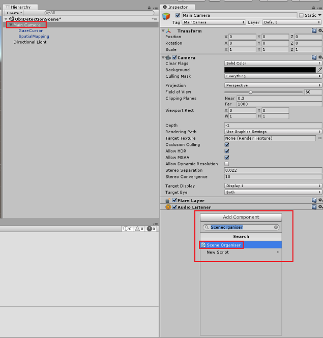
次の図に示されているように、[Project]\(プロジェクト\) パネルで、Prefabs フォルダーを開き、[Label]\(ラベル\) プレハブを、"Main Camera" に追加した SceneOrganiser スクリプトの "Label" という空の参照ターゲット入力領域にドラッグします。
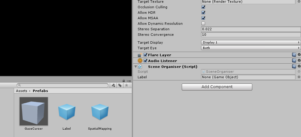
[階層] パネルで、[Main Camera] の子の [GazeCursor] を選択します。
[Inspector]\(インスペクター\) パネルで、GazeCursor が選択された状態で、[Add Component]\(コンポーネントの追加\) をクリックし、GazeCursor スクリプトを検索し、それをダブルクリックして追加します。
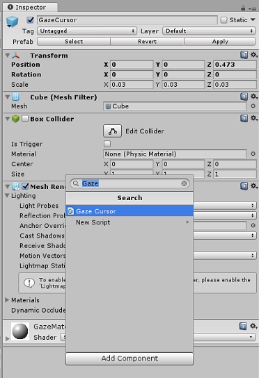
再び [階層] パネルで、[Main Camera] の子の [SpatialMapping] を選択します。
[インスペクター] パネルで、[SpatialMapping] が選択された状態で、[コンポーネントの追加] をクリックして、SpatialMapping スクリプトを検索し、それをダブルクリックして追加します。
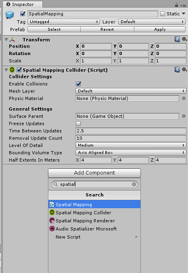
設定していない残りのスクリプトは、実行時に SceneOrganiser スクリプトのコードによって追加されます。
第 12 章 - ビルドする前に
アプリケーションの完全テストを実行するには、そのアプリケーションを Microsoft HoloLens にサイドロードする必要があります。
実行する前に、次のことを確認してください。
第 3 章に記載されている設定がすべて正しく設定されている。
SceneOrganiser スクリプトが Main Camera オブジェクトにアタッチされている。
GazeCursor スクリプトが GazeCursor オブジェクトにアタッチされている。
SpatialMapping スクリプトが SpatialMapping オブジェクトにアタッチされている。
第 5 章のステップ 6 で:
- predictionKey 変数にサービス予測キーを挿入したことを確認する。
- predictionEndpoint クラスに予測エンドポイントを挿入した。
第 13 章 – UWP ソリューションをビルドし、アプリケーションをサイドロードする
これで、アプリケーションを、Microsoft HoloLens にデプロイできる UWP ソリューションとしてビルドする準備ができました。 ビルド プロセスを開始するには、次の手順を実行します。
[ファイル] > [ビルド設定] に移動します。
[Unity C# プロジェクト] をオンにします。
[開いているシーンを追加] をクリックします。 これにより、現在開いているシーンがビルドに追加されます。
![[開いているシーンの追加] ボタンが強調表示されているスクリーンショット。](images/azurelabs-lab310-42.png)
[ビルド] をクリックします。 Unity によって [エクスプローラー] ウィンドウが起動されます。そこで、アプリのビルド先のフォルダーを作成して選択する必要があります。 そのフォルダーを作成して、「App」という名前を付けます。 次に、App フォルダーが選択された状態で、[Select Folder] (フォルダーの選択) をクリックします。
Unity で、App フォルダーに対してプロジェクトのビルドが開始されます。
Unity によるビルドが完了すると (多少時間がかかる場合があります)、[エクスプローラー] ウィンドウが開いて、ビルドの場所が表示されます (必ずしも最前面に表示されるとは限らないため、タスク バーを確認してください。新しいウィンドウが追加されたことがわかります)。
Microsoft HoloLens にデプロイするには、そのデバイスの IP アドレスが必要であり (リモート デプロイの場合)、またそのデバイスで開発者モードが設定されていることを確認する必要があります。 手順は次のとおりです。
HoloLens の装着中に、[設定] を開きます。
[ ネットワークとインターネット>Wi-Fi>Advanced オプションに移動します
IPv4 アドレスを書き留めます。
次に、 Settings に戻り、 Update と Security>For Developers に移動します。
Developer Mode On を設定します。
新しいユニティビルド(アプリフォルダー)にナビゲートし、Visual Studioでソリューションファイルを開きます。
[ソリューション構成] で、[デバッグ] を選択します。
[ソリューション プラットフォーム] で、[X86]、[リモート コンピューター] を選択します。 リモート デバイスの (この場合は、メモした Microsoft HoloLens の) IP アドレスを挿入するように求められます。

[ビルド] メニューに移動し、[ソリューションのデプロイ] をクリックして、アプリケーションを HoloLens にサイドロードします。
Microsoft HoloLens にインストールされたアプリの一覧にこのアプリが表示され、起動できる状態になります。
アプリケーションを使用するには:
- Azure Custom Vision サービスの物体検出でトレーニングした物体を見て、タップ ジェスチャを使用します。
- 物体が正常に検出されると、ワールド空間の "ラベル テキスト" がタグ名と共に表示されます。
重要
写真をキャプチャしてサービスに送信するたびに、[サービス] ページに戻って、新しくキャプチャした画像を使用してサービスを再トレーニングできます。 最初は、多くの場合、"境界ボックス" がより正確になるように修正して、サービスを再トレーニングする必要があります。
Note
Microsoft HoloLens のセンサー、Unity の SpatialTrackingComponent、またはこれらの両方で、現実世界の物体を基準として適切なコライダーを配置できない場合、配置されるラベル テキストが物体の近くに表示されないことがあります。 その場合は、別のサーフェスでアプリケーションを使用してみてください。
独自の Custom Vision の物体検出アプリケーション
作業はこれで終了です。Azure Custom Vision の物体検出 API を活用する複合現実アプリを構築しました。このアプリでは、画像から物体を認識し、3D 空間でその物体のおおよその位置を示すことができます。

ボーナス演習
演習 1
テキスト ラベルに追加して、半透明の立方体を使用し、3D の "境界ボックス" 内に現実物体が包含されるようにします。
演習 2
より多くの物体を認識できるように Custom Vision サービスをトレーニングします。
演習 3
物体が認識されたときにサウンドを再生します。
演習 4
API を使用して、アプリで分析しているのと同じ画像を使用してサービスを再トレーニングし、サービスの精度を高めます (予測とトレーニングの両方を同時に行います)。