Step-by-step for deploying a SDNv2 using VMM - Part 3
In this post, we will continue and walk through the steps to deploy SLB. Most of the steps here are same as the following official validation guide. However I will highlight some of the error-prone steps and provide step-by-step screenshots.
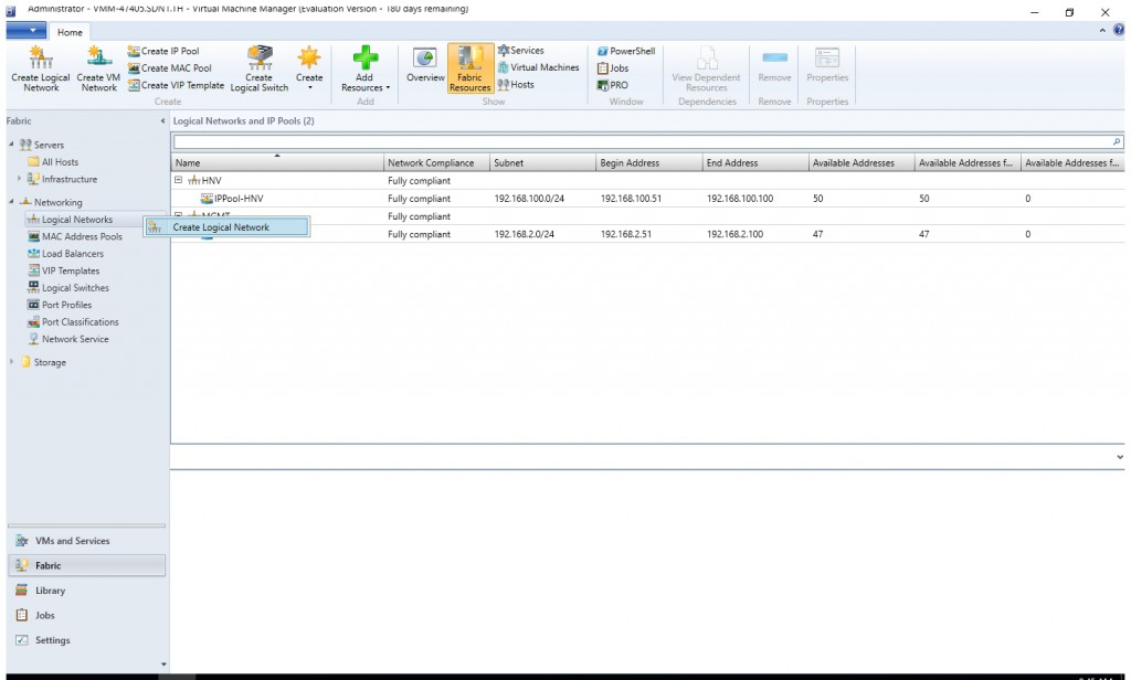
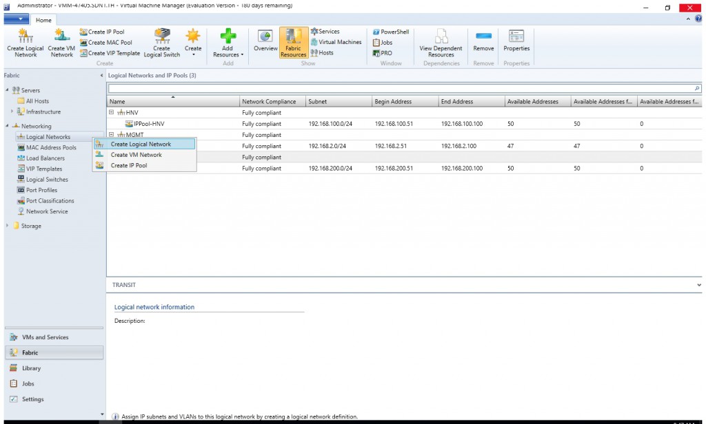
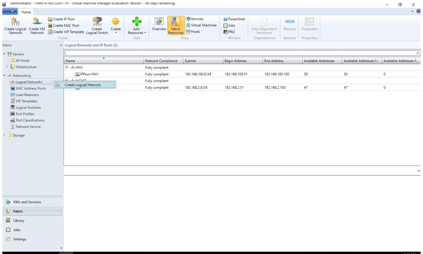
Create Logical Network "TRANSIT", "Private VIP" and "Public VIP"
- From the VMM console, start the Create logical network Wizard.
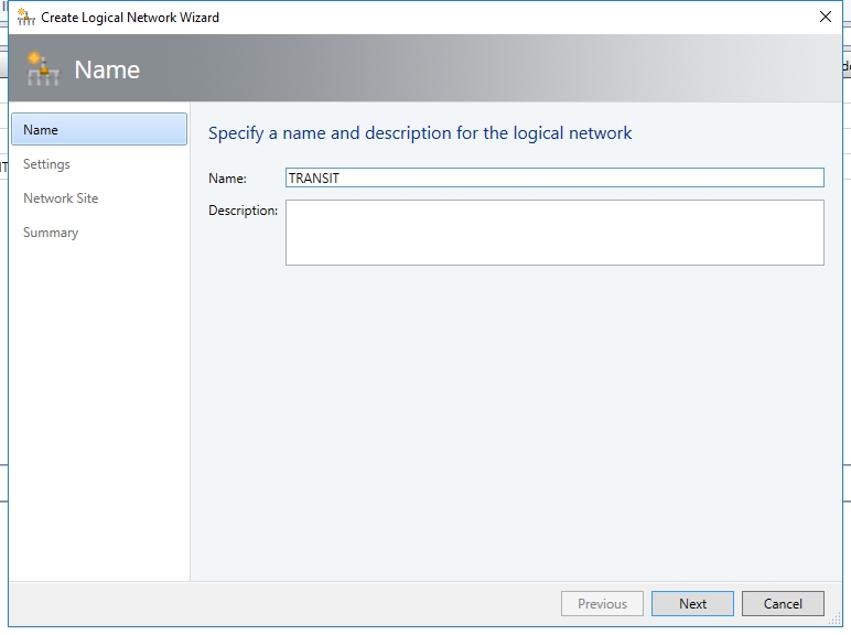
- Type a name and optional description for this network and click Next.
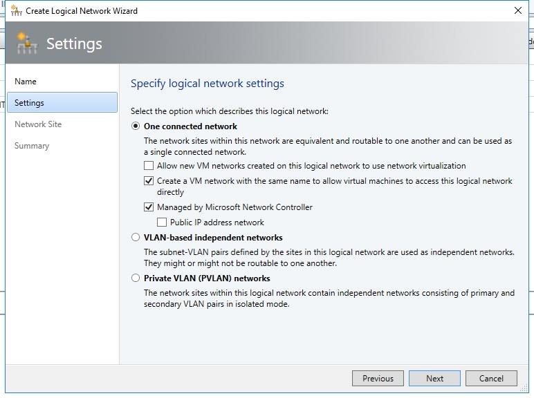
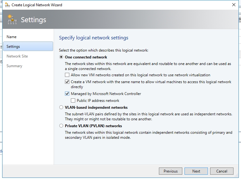
- On the Settings page, ensure you select One Connected Network. Check Create a VM network with the same name box to allow virtual machines to access this logical network directly and the Managed by the network controller box then click Next.
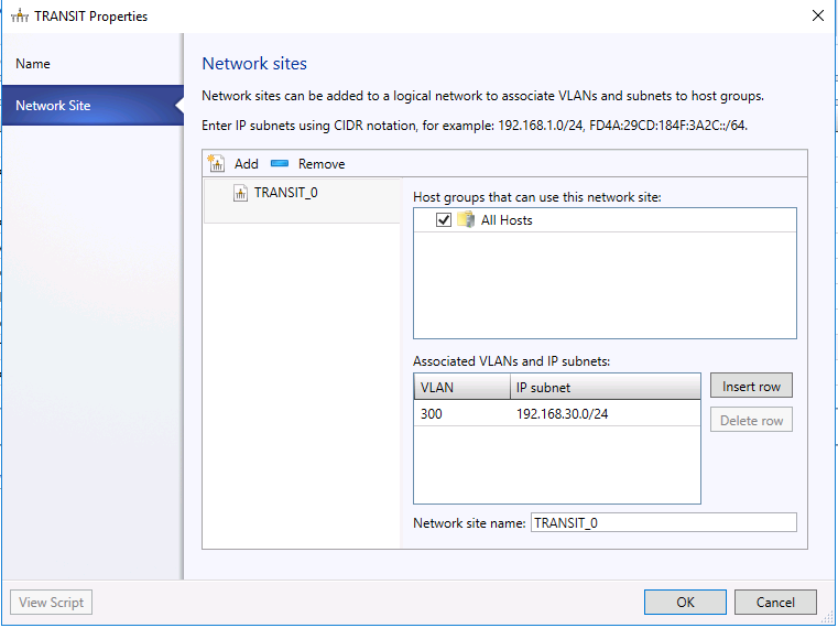
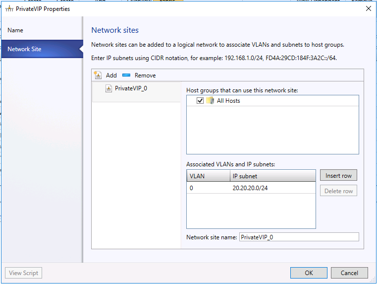
- On the Network Site panel, add the network site information for your subnet.
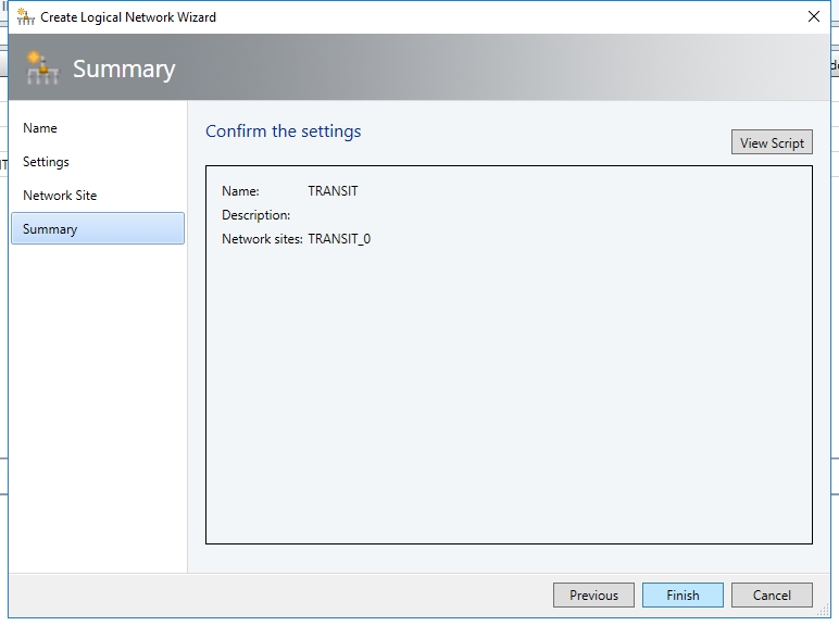
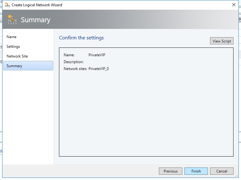
- Review the Summary information and complete the logical network wizard
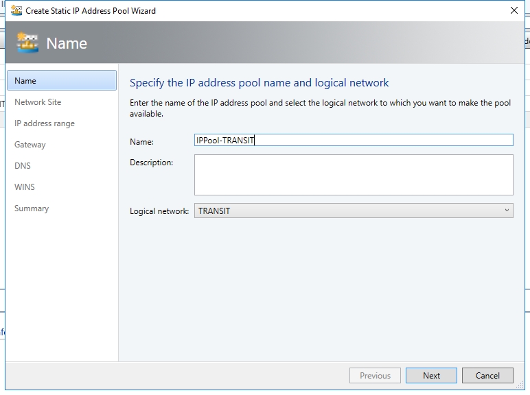
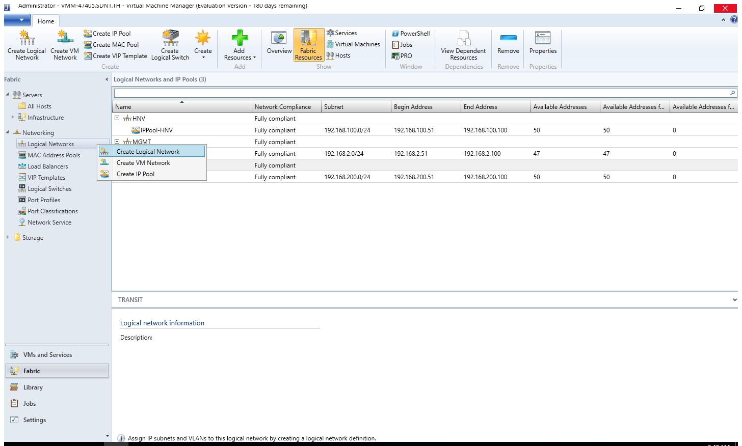
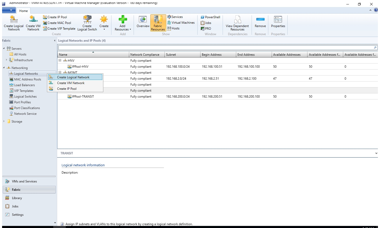
- Create IP Address pool for the new created TRANSIT logical network.
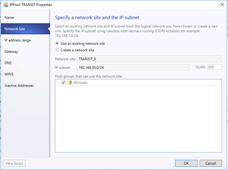
- Use the existing network site.
- Set starting IP address 192.168.30.51 and ending IP address 192.168.30.100.
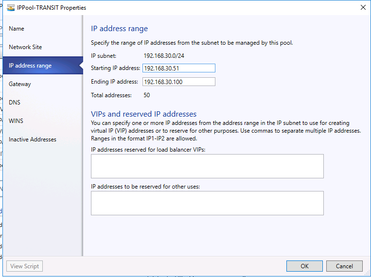
- The default gateway is 192.168.30.1.
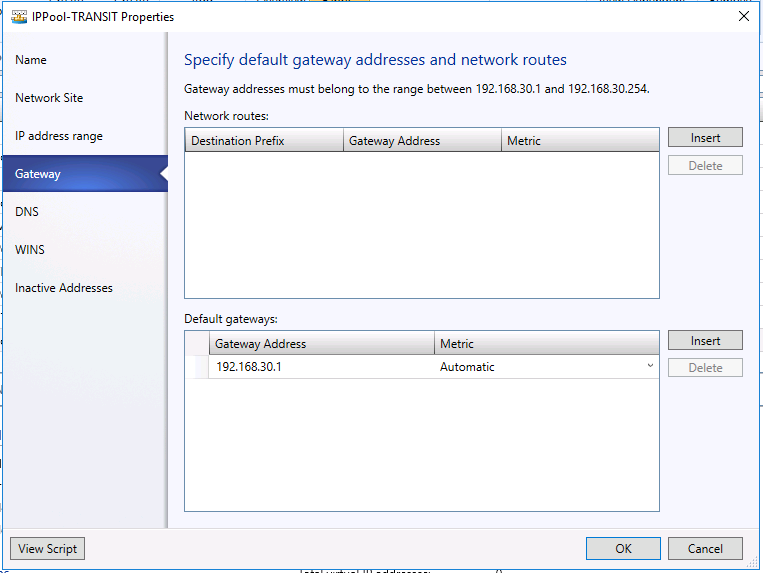
- On Summary page, click Finish.
- Start the Create logical network Wizard.
- Type a name and optional description for this network. Click Next.

- On the Settings page, ensure you select One Connected Network. check Create a VM network with the same name box to allow virtual machines to access this logical network directly and the Managed by the network controller box then click Next.
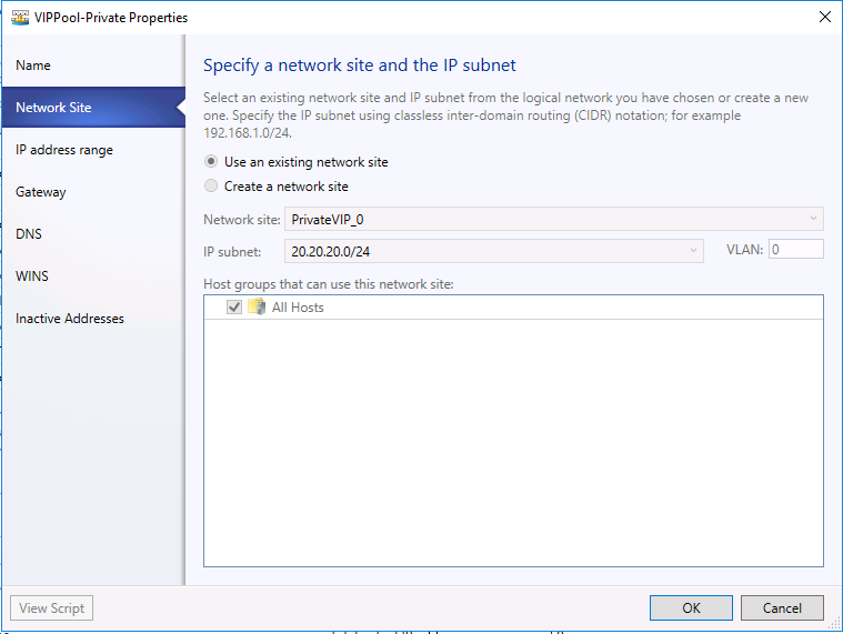
- On the Network Site panel, add the network site information for your Private VIP logical network. VLAN ID is "0" and in my case the IP subnet is "20.20.20.0/24".
- Review the Summary information and complete the wizard.
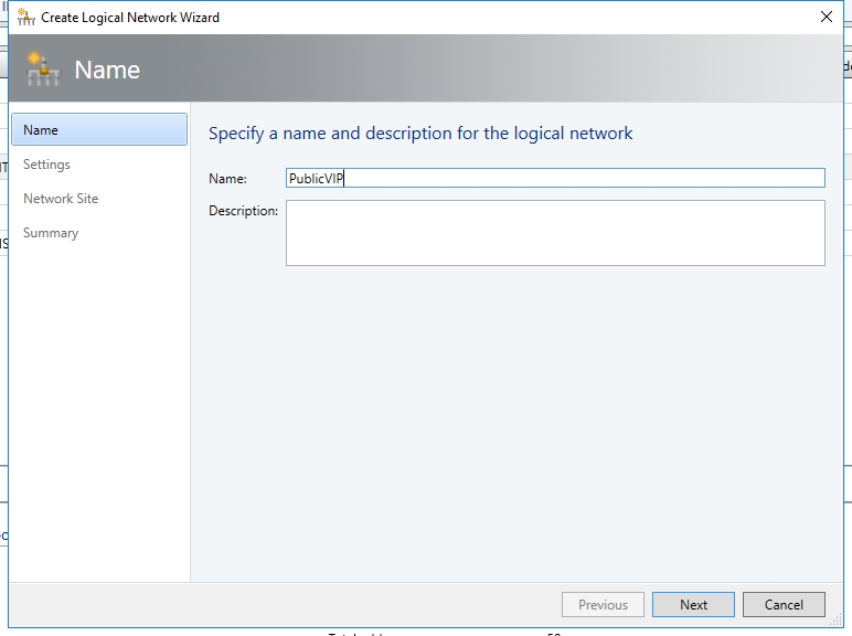
- Start the Create logical network Wizard.

- Type a name and optional description for this network and click Next.
- On the Settings page, ensure you select One Connected Network. Check the Create a VM network with the same name box to allow virtual machines to access this logical network directly and the Managed by the network controller box. Also select Public IP Address Network and then click Next.

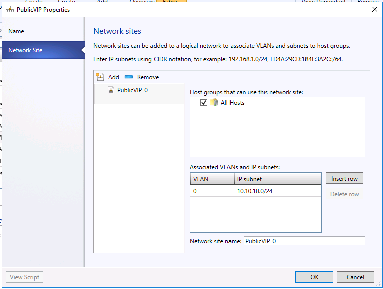
- On the Network Site panel, add the network site information for your Public VIP network. This should include the Host Group and subnet information for your Public VIP network.
- Review the Summary information and complete the logical network wizard

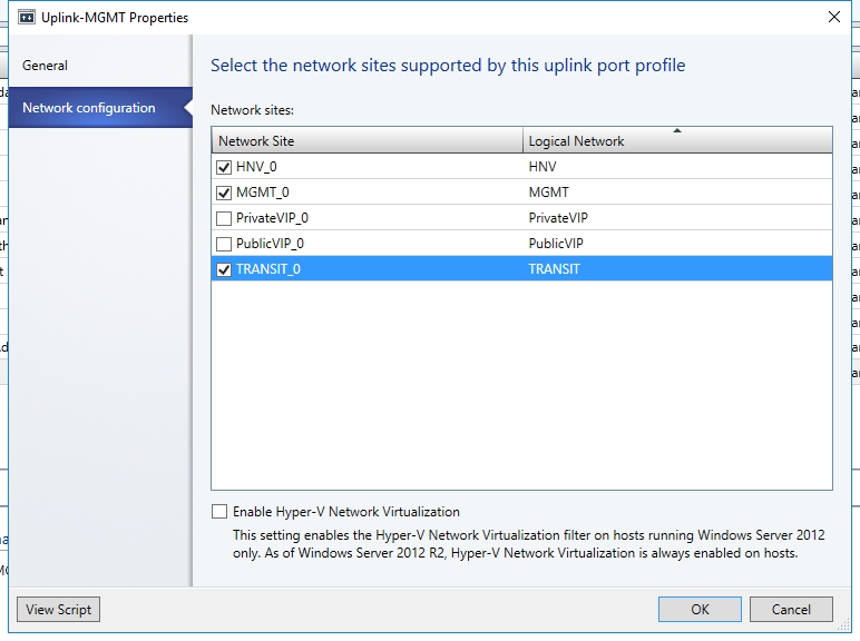
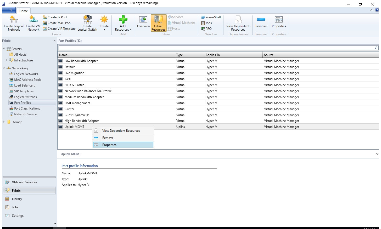
- Right click "Uplink-MGMT" and select Properties.
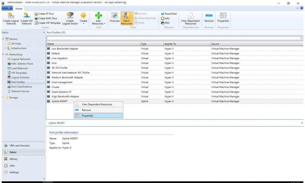
- Associate this logical network with the Management switch uplink port profile you created during the network controller deployment.
Create VIP Pool for Private VIP Logical Network
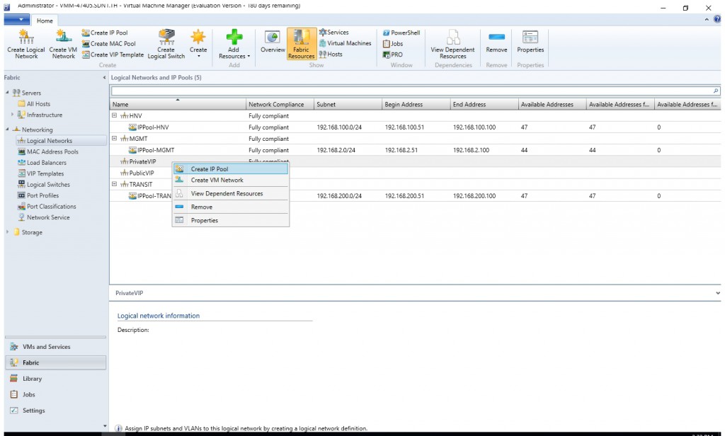
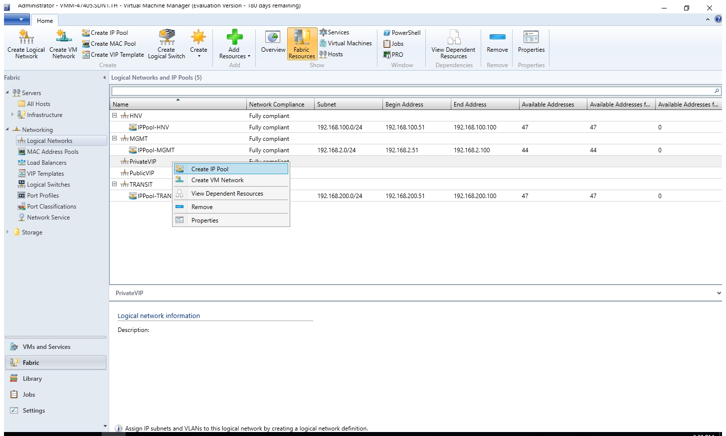
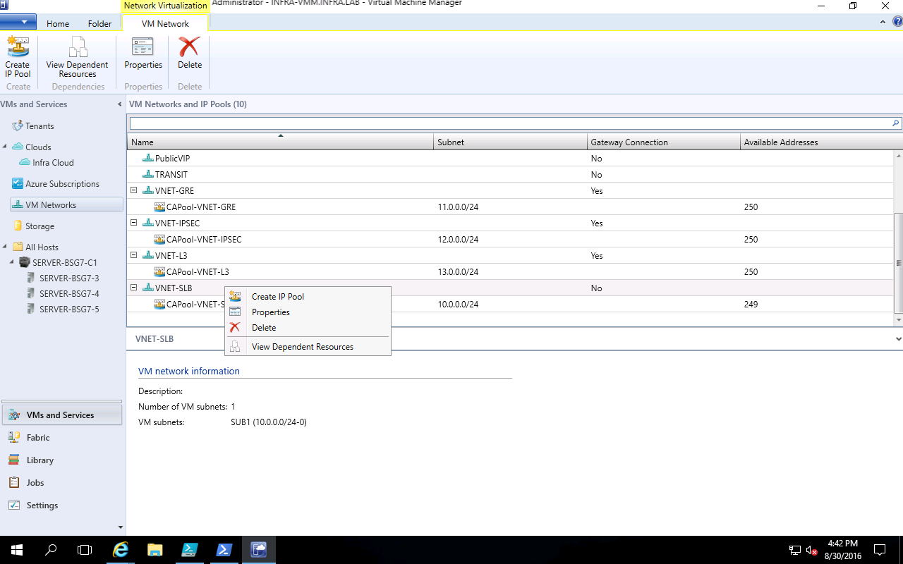
- Right-click the Private VIP logical network in VMM and select Create IP Pool from the drop down menu.
- Provide a name and optional description for the IP Pool and ensure that the Private VIP logical network is selected for the logical network. Click Next.

- Accept the default network site and click Next.
- Choose a starting and ending IP address for your range.

 Important
Start your range on the fourth addresses of your available subnet. For example, if your available subnet is from .1 to .254, start your range at .4. - In the IP addresses reserved for load balancer VIPs box, type the IP addresses range in the subnet. This should match the range you used for starting and ending IP addresses.
- You do not need to provide gateway, DNS or WINS information as this pool is used to allocate IP addresses for VIPs only via the network controller, so click Next to skip these screens.
- Review the summary information and complete the wizard.
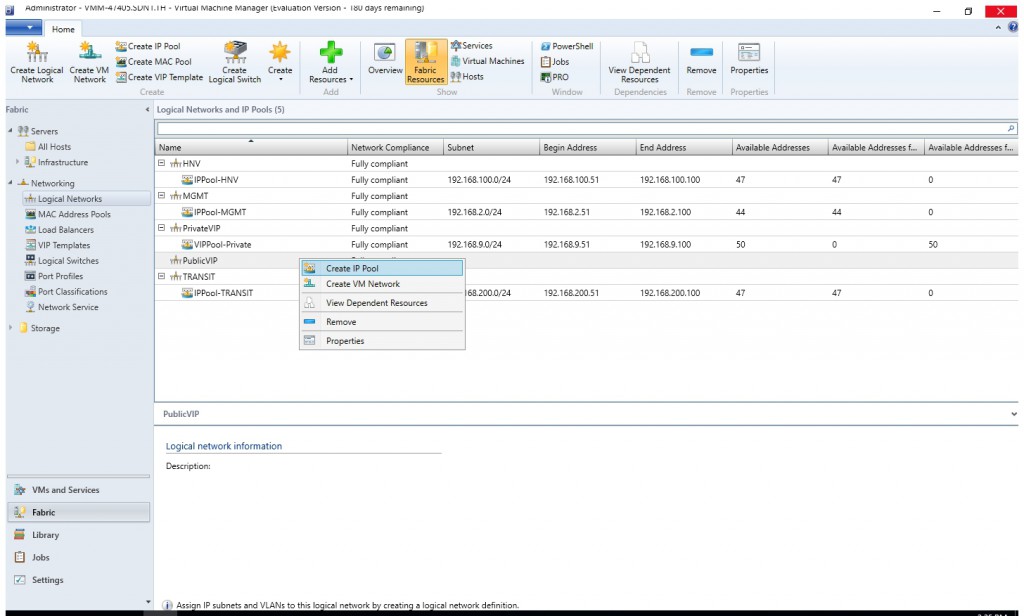
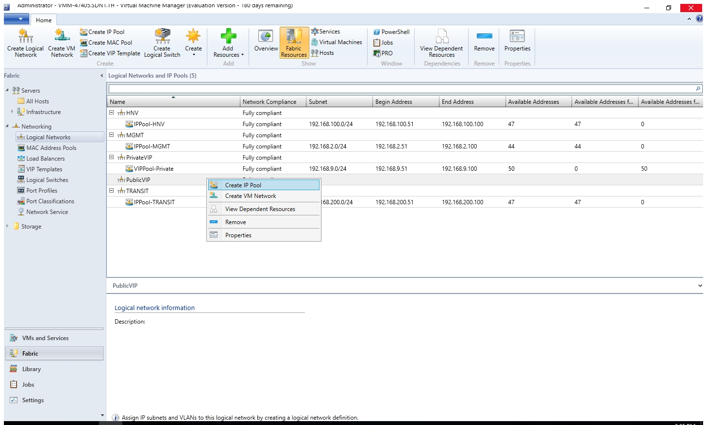
Create VIP Pool for Public VIP Logical Network
- Right-click the Public VIP logical network in VMM and select Create IP Pool from the drop down menu.
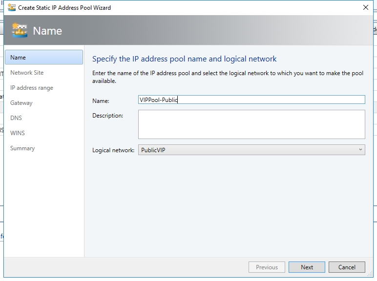
- Provide a name and optional description for the IP Pool and ensure that the VIP network is selected for the logical network. Click Next.
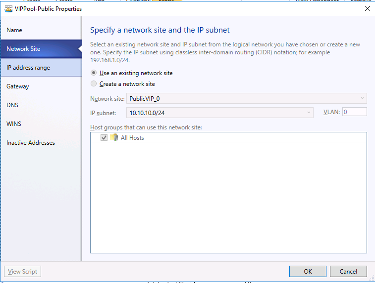
- Accept the default network site and click Next.
- Choose a starting and ending IP address for your range.
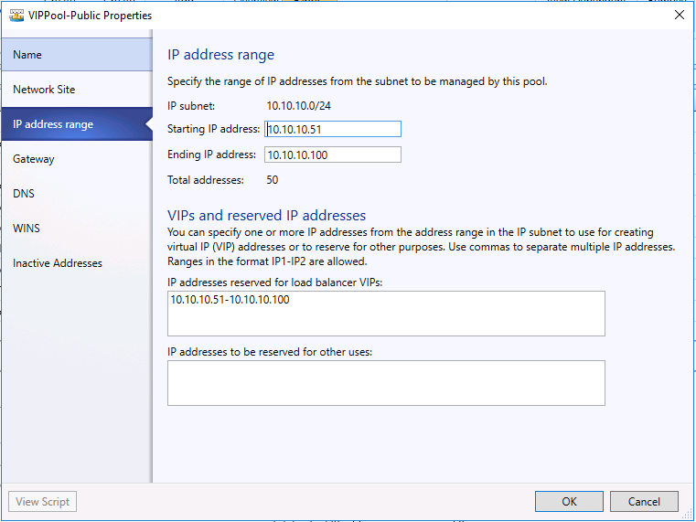 Important
Start your range on the fourth addresses of your available subnet. For example, if your available subnet is from .1 to .254, start your range at .4. - In the IP addresses reserved for load balancer VIPs box, type the IP addresses range in the subnet. This should match the range you used for starting and ending IP addresses.
- You do not need to provide gateway, DNS or WINS information as this pool is used to allocate IP addresses for VIPs only via the network controller, so click Next to skip these screens.
- Review the summary information and complete the wizard
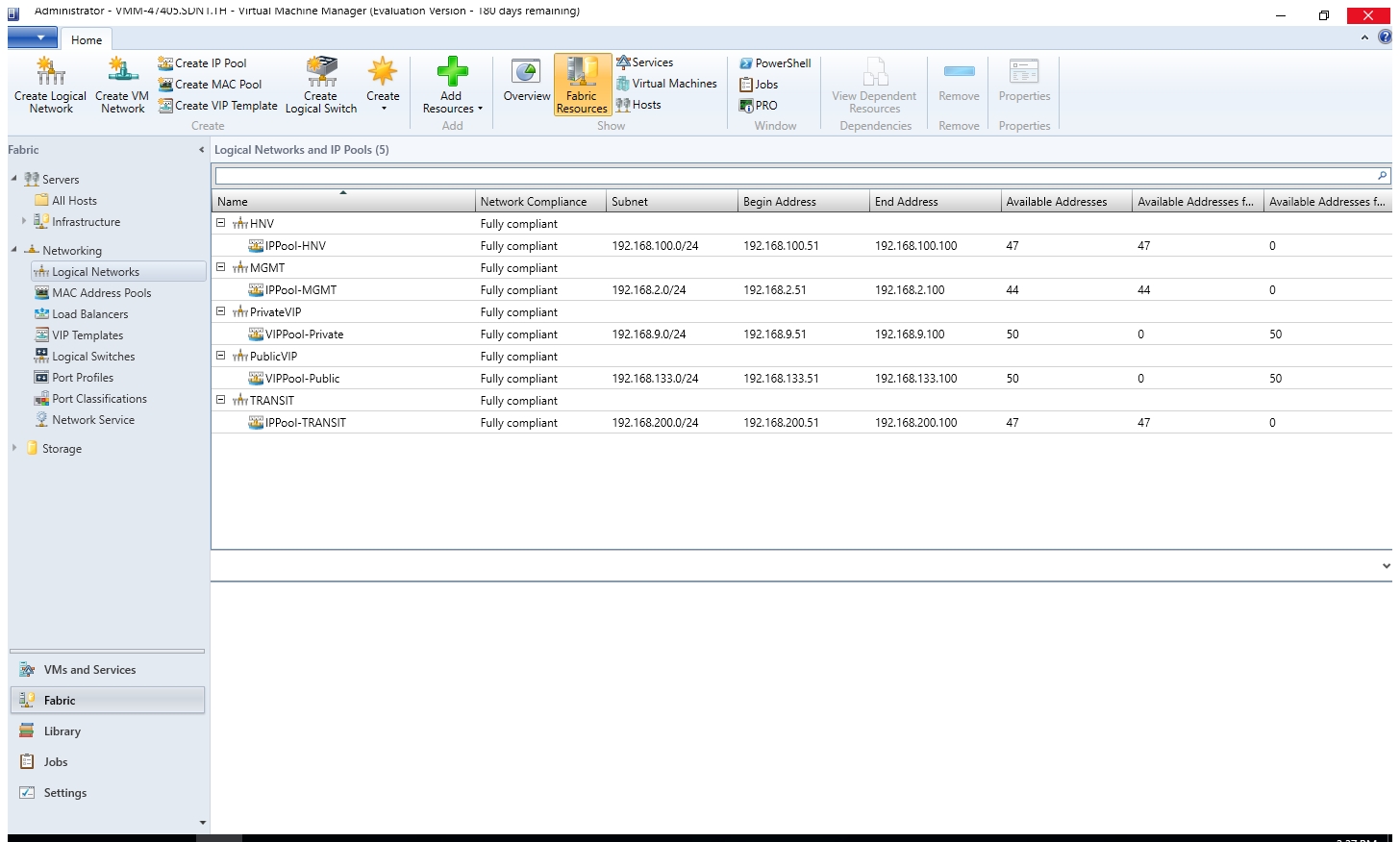
- Now you had already configured all the logical network and IP pool.

Create SLB service
- In the VMM console, navigate to Library.
- In the top of the left pane, in the Templates section, select Service Templates.
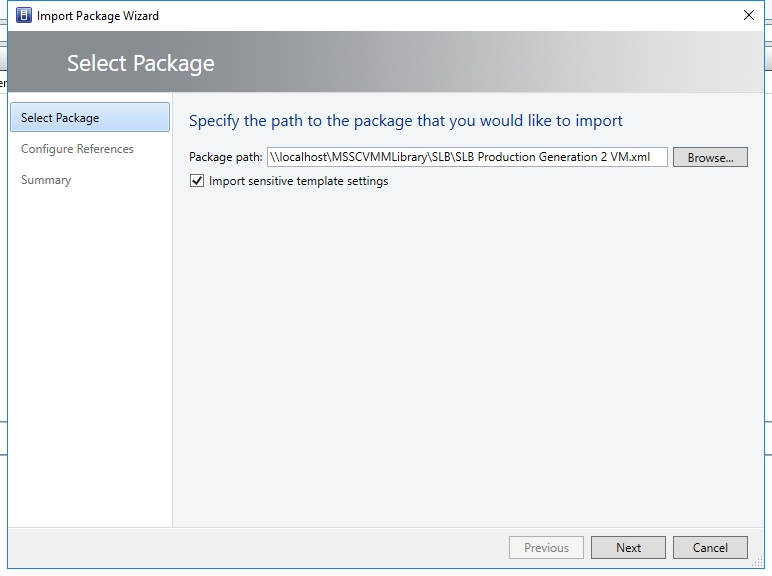
- In the ribbon at the top, click Import Template.
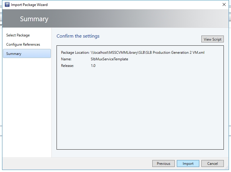
- Browse to your service template directory, select the SLB Production Generation 2 VM.xml file and follow the prompts to import it.
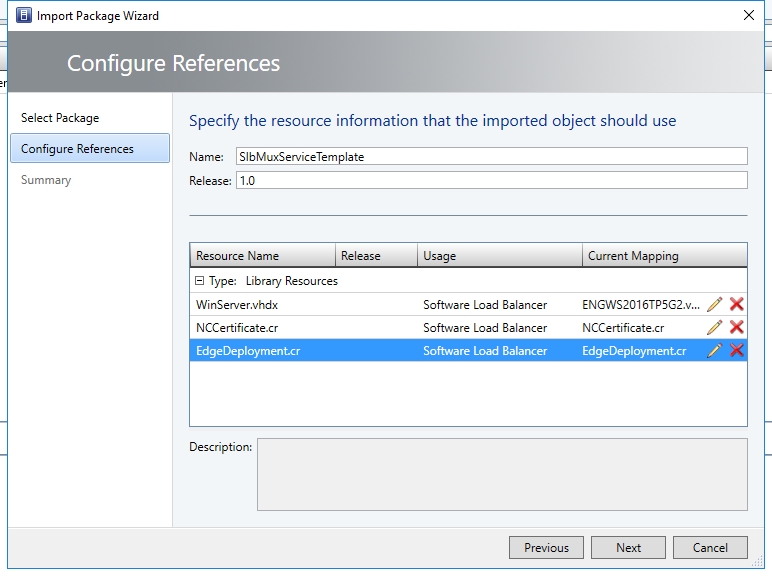
- This service template uses the following virtual machine configuration parameters. Update the parameters to reflect your environment configuration.
- On Summary, click "Import".
- If your syspreped image is based on volume license image, you may jump to step 11.
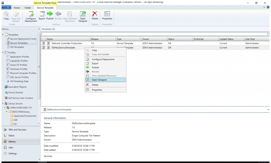
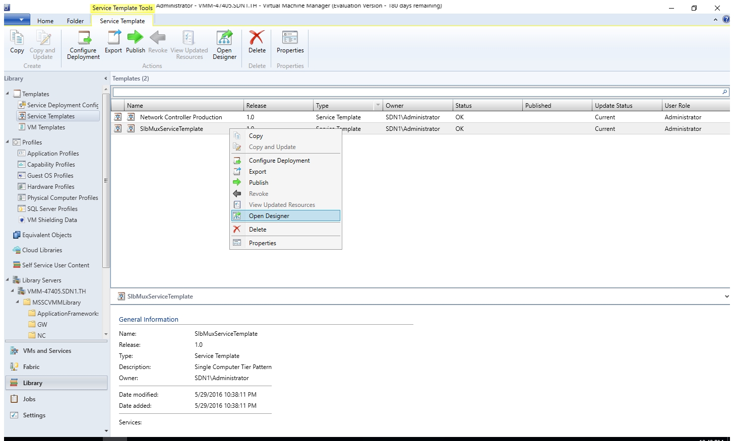
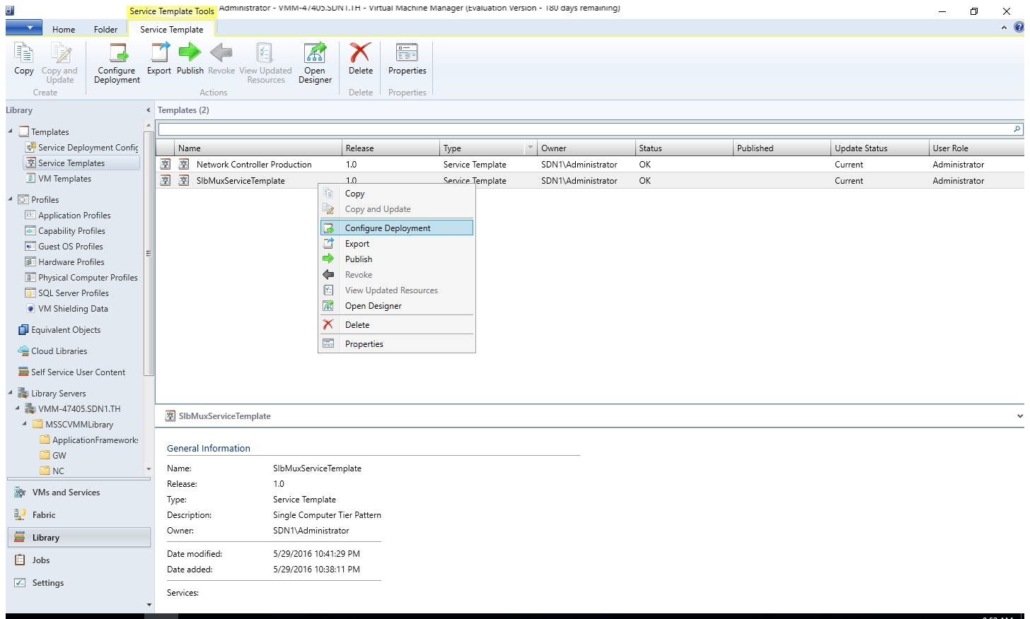
- (Optional) If your syspreped image is not based on volume license image, you need to modify the service template and input the product key. Right click "SlbMuxServiceTemplate" and select "Open Designer".
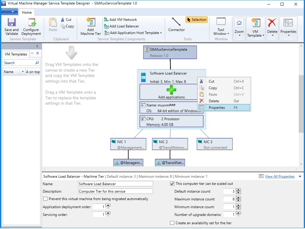
- Right click "Software Load Balancer" and select "Properties".
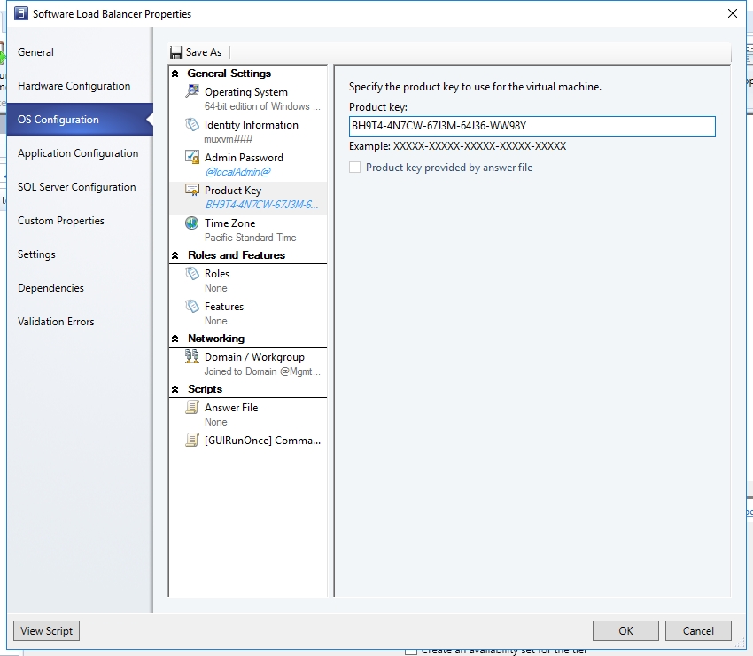
- Type the product key.
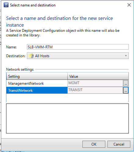
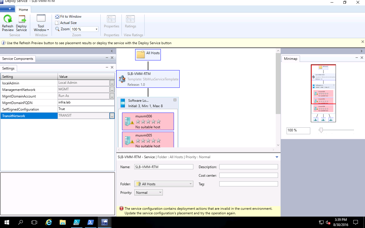
- Right click "Software Load Balancer" and select "Configure Deployment".

- Type the name "SLB-VMM-RTM". Select the corresponding Transit network and Management network.
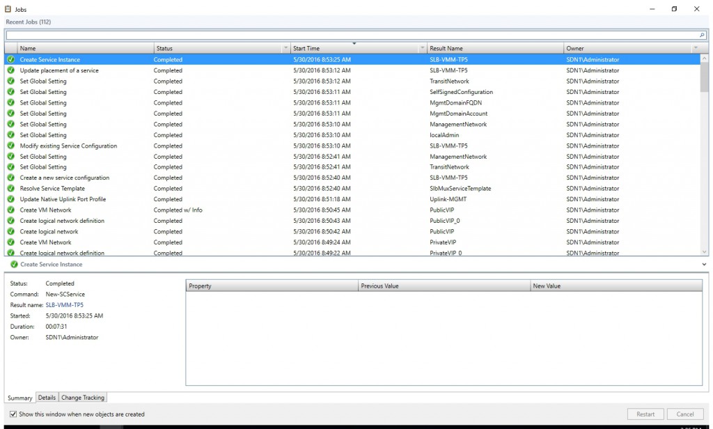
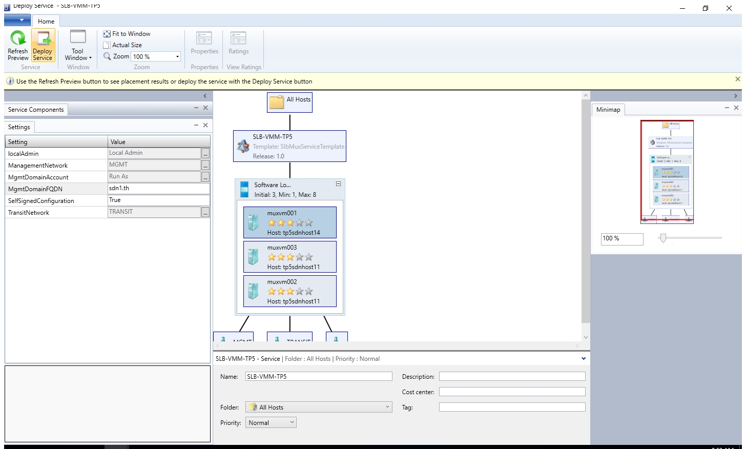
- Configure the settings in the page below. Then click "Refresh". Then click "Deploy Service".

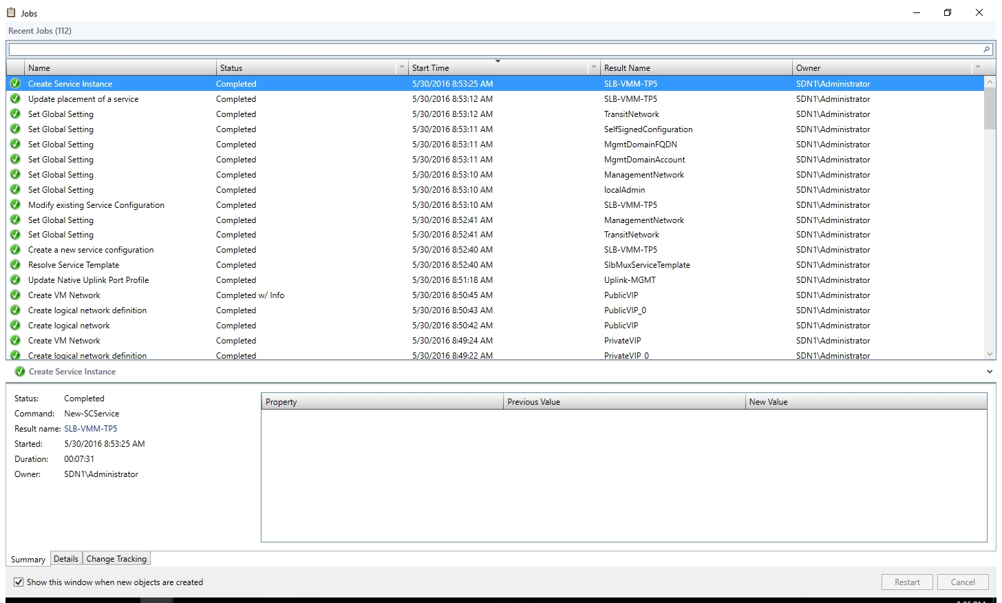
- Make sure the deployment complete successfully.
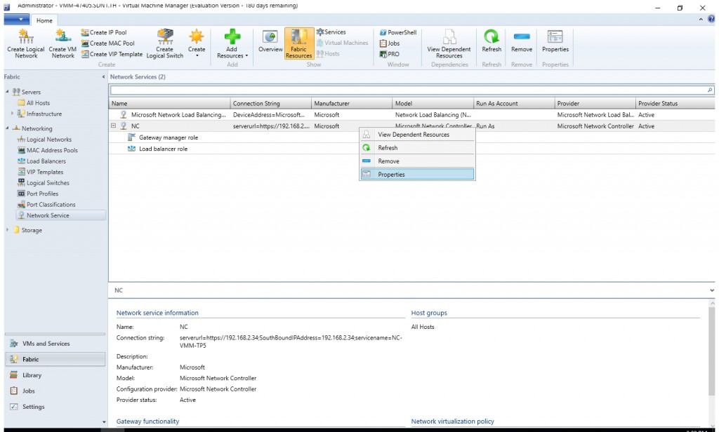
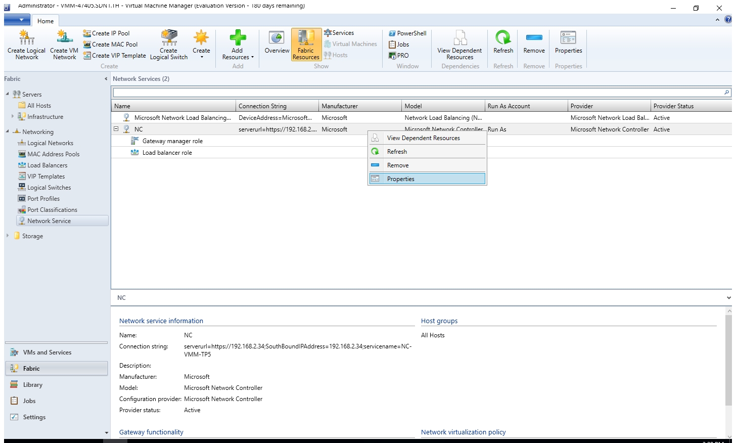
- Open the Fabric workspace.
- Click Network Service to display the list of network services installed.
- Right-click the network controller service and select Properties.
- In the Wizard, Select the Services tab, and then click Load Balancer Role
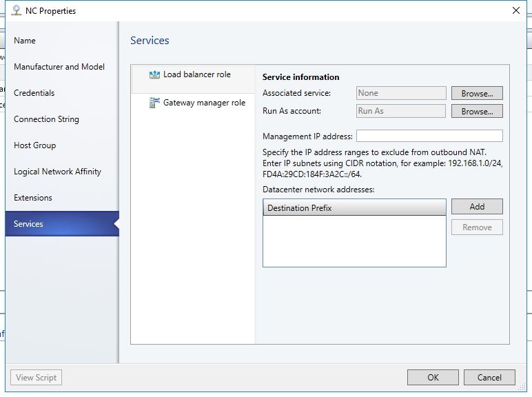
- Find the Associated Service field under Service information and click Browse. Select the SLB/MUX service instance you created earlier and click OK.
- Choose the appropriate Run as Account.
- For the Management IP address, use the last IP address from the Private VIP pool you created earlier. In my case, it's 20.20.20.100. In addition, please select Public IP pool and private IP pool you just created. VMM will advertise those VIP address pools to the SLB Manager.

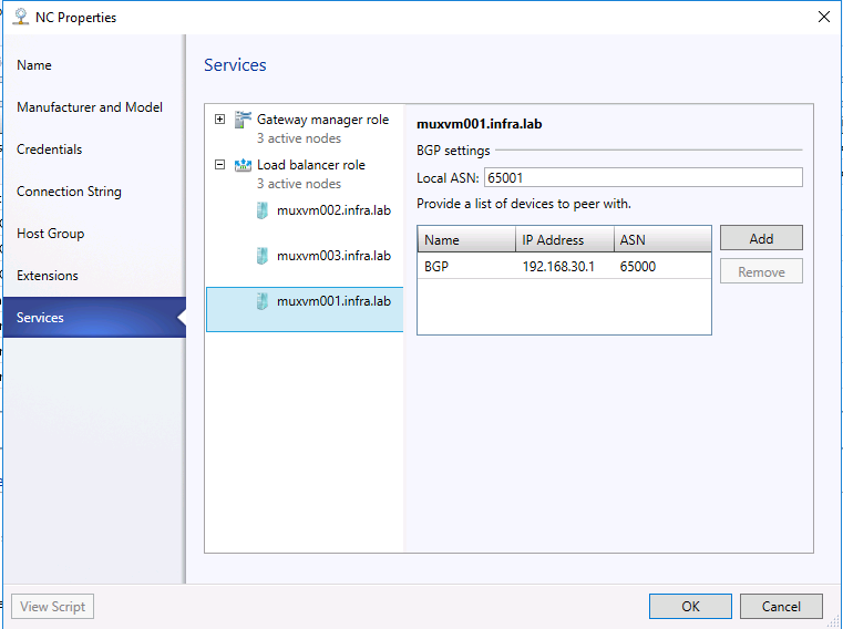
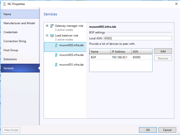
- Click the SLB/MUX instance listed under Load Balancer Role in the wizard.
- Type the local ASN for your datacenter and details for the devices or BGP peers the SLB/MUX can peer with. You should use the Transit network for BGP peering. (In TP5, we use MGMT network for BGP Peering.)

- Make sure associate service instance with fabric role.
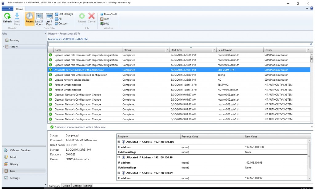
- The SLB Service instance is now associated with the SLBM service, and you should see the SLB/MUX virtual machine instance with all the settings listed under the Load Balancer role.


Configure BGP Router
W may use Windows Server 2016 RRAS as the BGP Router. Assume RRAS role had already been installed on the BGP VM (In my case, it's "INFRA-BGPNAT". Run the script below to configure the BGP router.
Add-BgpRouter -BgpIdentifier 192.168.30.1 -LocalASN 65000
 add-bgppeer -Name MUX001 -LocalIPAddress 192.168.30.1 -PeerIPAddress 192.168.30.53 -LocalASN 65000 -PeerASN 65001 -OperationMode Mixed -PeeringMode Automatic
add-bgppeer -Name MUX002 -LocalIPAddress 192.168.30.1 -PeerIPAddress 192.168.30.52 -LocalASN 65000 -PeerASN 65002 -OperationMode Mixed -PeeringMode Automatic
add-bgppeer -Name MUX003 -LocalIPAddress 192.168.30.1 -PeerIPAddress 192.168.30.51 -LocalASN 65000 -PeerASN 65003 -OperationMode Mixed -PeeringMode Automatic
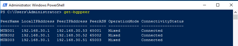
You may use cmdlet Get-BgpPeer to check if they're connected.
Create a VIP Template
Use the following procedure to create a VIP template.
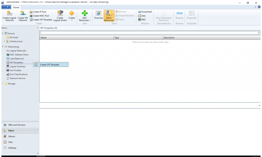
- Navigate to the Fabric Workspace in the VMM console.
- Right click the VIP Templates node and select Create VIP Template, or alternately you can click the Create VIP Template in the ribbon toolbar.
- Type a name in the Template Name field and an optional description in the Description field.
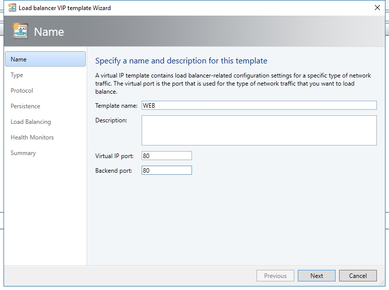
- In the Virtual IP Port field, provide a value for the port you wish to test.
- For the Backend Port, provide a value for the port from which you wish to map traffic on the back end.
- Click Next.
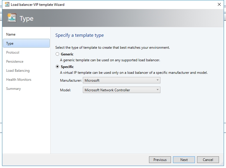
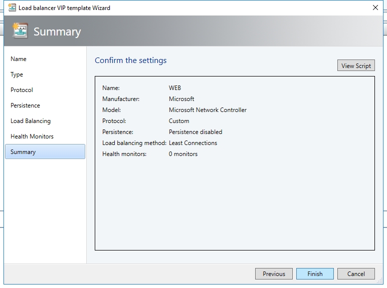
- On the Specify a Template Type screen, click Specific, and select Microsoft for the Manufacturer and for the Model, select Microsoft network controller. Click Next.
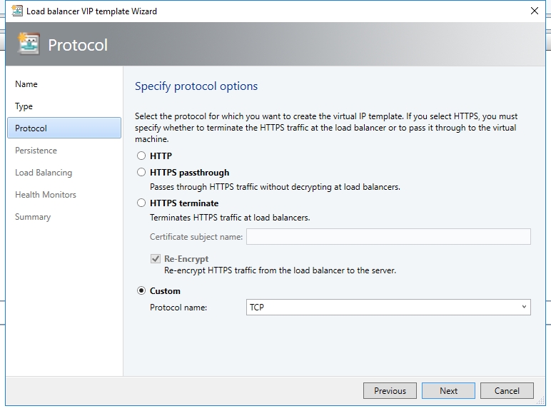
- On the Specify Protocol Options screen, select the Custom option and type TCP in the Protocol Name field. Click Next.
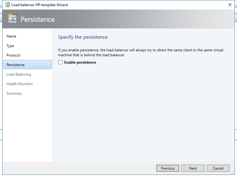
- You can optionally select enable persistence if you wish to have the load balancer make the connection from the client “sticky”. Click Next.
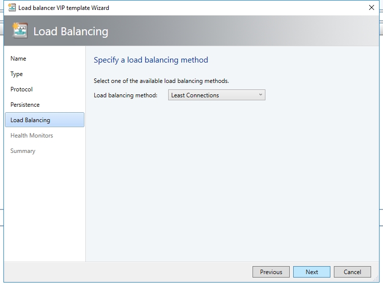
- For the Load Balancing method, select Round Robin from the drop down list. Click Next.
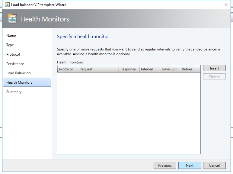
- On Health Monitors page, click Next to move past this screen.
- Confirm your settings and then click Finish when you are ready to create the VIP Template.

Validation
Test Case 2: SLB
The following sample PowerShell script creates a VIP for two virtual machines (TESTVMSLB1 and TESTVMSLB2). The script should be run on the VMM server, or on a computer running the VMM Console.
param(
 [Parameter(Mandatory=$false)]
# Name of the Network Controller Network Service
# This value should be the name you gave the Network Controller service
# when you on-boarded the Network Controller to VMM
$LBServiceName = "NC",
 [Parameter(Mandatory=$false)]
# Name of the VM instances to which you want to assign the VIP
$VipMemberVMNames =  @("TESTVMSLB1","TESTVMSLB2"),
 [Parameter(Mandatory=$false)]
# VIP address you want to assign from the VIP pool.
# Pick any VIP that falls within your VIP IP Pool range.
$VipAddress = "10.10.10.100",
 [Parameter(Mandatory=$false)]
# Name of the VIP VM Network
$VipNetworkName = "PublicVIP",
 [Parameter(Mandatory=$false)]
# The name of the VIP template you created via the VMM Console.
$VipTemplateName = "WEB",
 [Parameter(Mandatory=$false)]
# Arbitrary but good to match the VIP you're using.
$VipName = "scvmm_10_10_10_100_80"
)
Import-Module virtualmachinemanager
 $lb = Get-scLoadBalancer | where { $_.Service.Name -like $LBServiceName};
$vipNetwork = get-scvmnetwork -Name $VipNetworkName;
 $vipMemberNics = @();
foreach ($vmName in $VipMemberVMNames)
{
$vm = get-scvirtualmachine -Name $vmName;
#    if ($vm.VirtualNetworkAdapters[0].VMNetwork.ID -ne $vipNetwork.ID)
#    {
#        $vm.VirtualNetworkAdapters[0] | set-scvirtualnetworkadapter -VMNetwork $vipNetwork;
#    }
 $vipMemberNics += $vm.VirtualNetworkAdapters[0];
}
 $existingVip = get-scloadbalancervip -Name $VipName
if ($existingVip -ne $null)
{
#    foreach ($mem in $existingVip.VipMembers)
#    {
#        $mem | remove-scloadbalancervipmember;
#    }
 $existingVip | remove-scloadbalancervip;
}
$vipt = get-scloadbalancerviptemplate -Name $VipTemplateName;
 $vip = New-SCLoadBalancerVIP -Name $VipName -LoadBalancer $lb -IPAddress $VipAddress -LoadBalancerVIPTemplate $vipt -FrontEndVMNetwork $vipNetwork -BackEndVirtualNetworkAdapters $vipMemberNics;
Write-Output "Created VIP " $vip;
 $vip = get-scloadbalancervip -Name $VipName;
Write-Output "VIP with members " $vip;
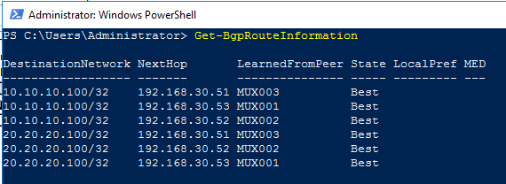
After create and assign public VIP to the above test VMs, you may run the cmdlet from BGP VM to verify the routing information to 10.10.10.100 had already been advertised to BGP router.
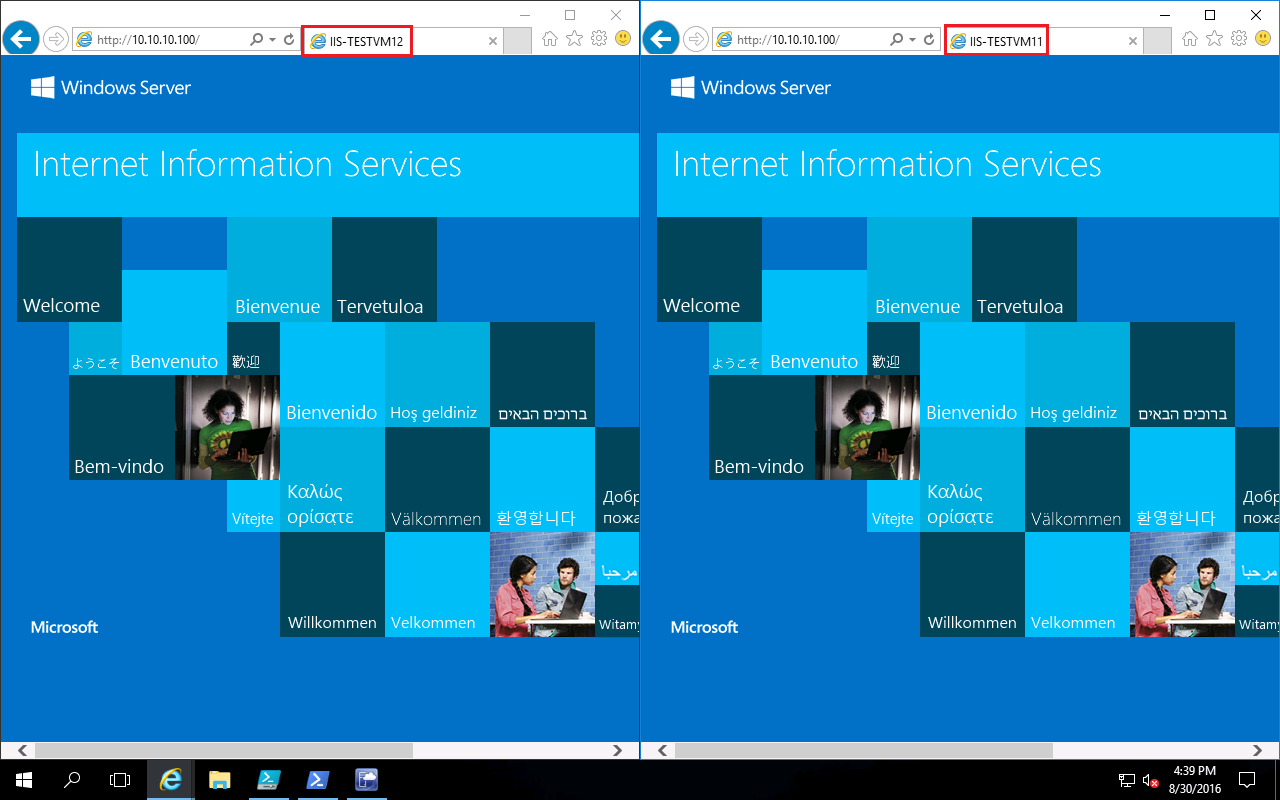
In order to validate the SLB functionality, you may install Web role on both TESTVMSLB1 and TESTVMSLB2. Then verify you are able to access https://10.10.10.100.
Test Case 3: SNAT
After you deploy and on-board the Software Load Balancer as a Network Service using VMM, you can use the VMM user interface to configure both inbound and outbound NAT rules.
Use the following steps to configure NAT:
- Open the VMM Administrator console and select the VMs and Services tab.
- Select the VM Networks tab and then double click the VM network you want to configure with NAT rules.
- Select the Connectivity tab on the property wizard.
- Check Connect directly to an additional Network and select Network Address Translation (NAT) .
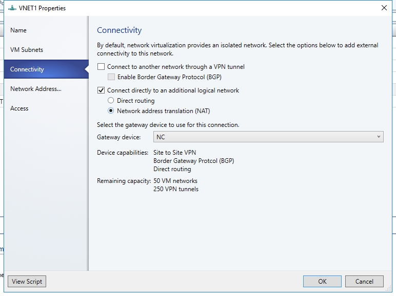
- In Gateway Device, select your network controller service name.
- Select the Network Address Translation tab. Then select the public IP pool.
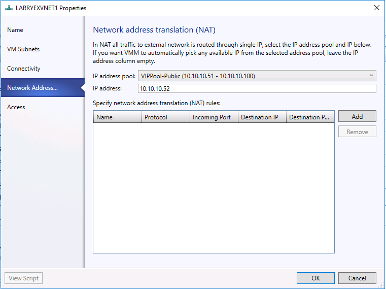
- In the IP address pool field, choose your Public VIP pool.
- Leave the IP address field empty. A VIP address will be automatically assigned to this rule.
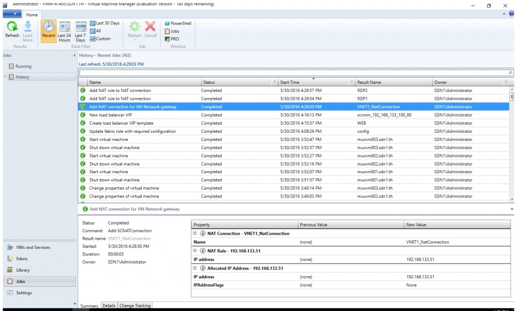
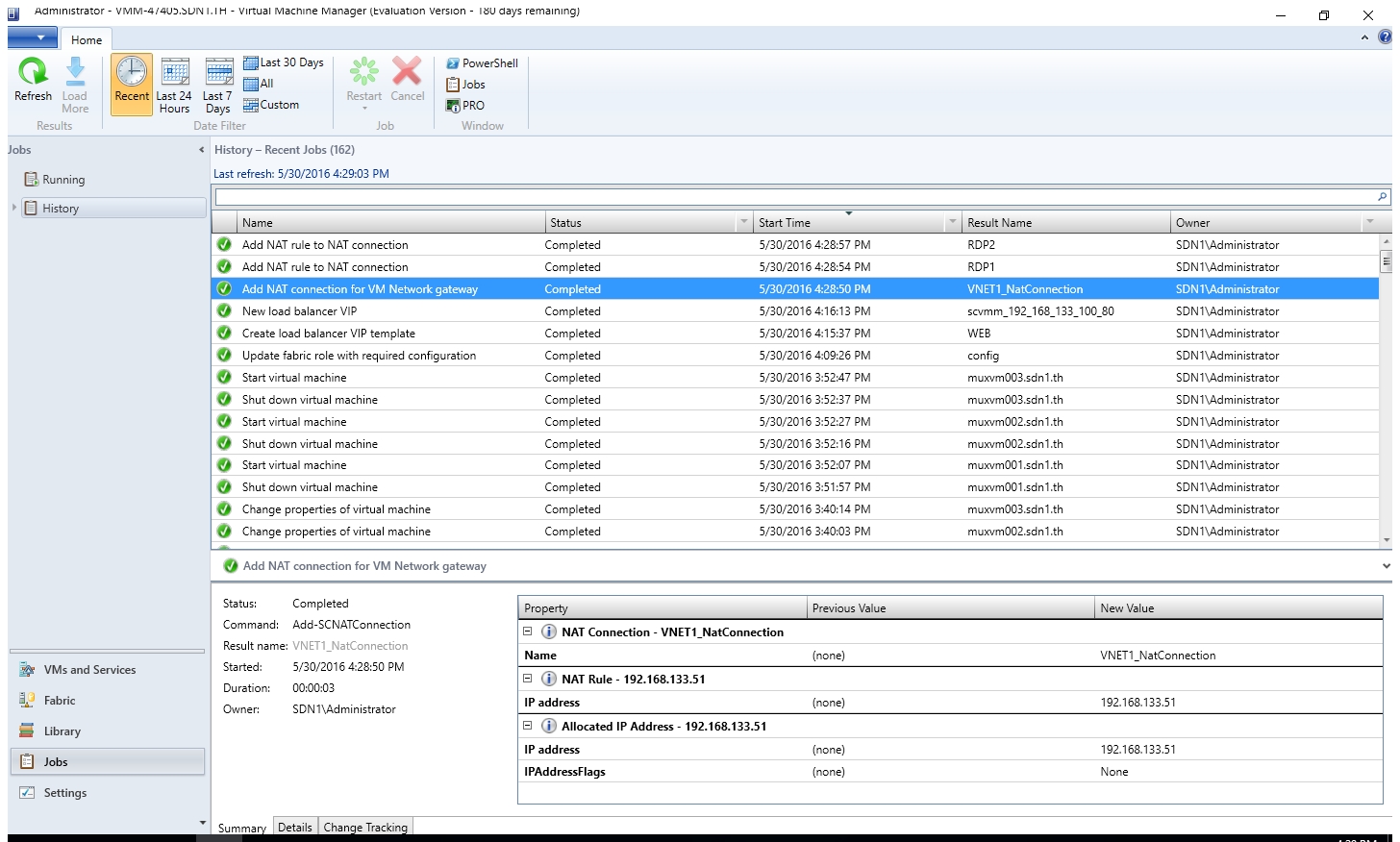
- Make sure add VM Network gateway successfully. And add the corresponding NAT rules successfully.
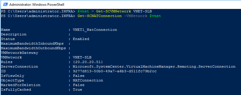
- You may also check the NAT connection and NAT rules with PowerShell.
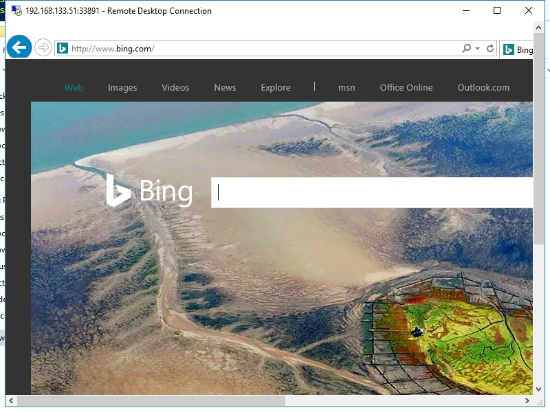
- You may also verify both inbound NAT and outbound NAT work as expected.
To Be Continued...
In the next post we will walk through gateway deployments.
Comments
- Anonymous
June 16, 2016
Hi! Very helpful blog you have here. It'd be a shame if someone was to... comment it.But seriously, this is a very helpful procedure. Thank you. I do have a few questions tough: I'm curently trying this procedure on my physical setup. My BGP peer would be a Catalyst 4500 switch from cisco. Except when specifying the asn and the bgp peer adress, I don't see any configuration on the switch so I'm wondering: Do I have to enter the bgp peer (the slbmux) in my cisco switch? If so, I suppose I have to enter every VM that have been created, with their management IP adress, correct? I can't get the ip adress of my machines before I create the machines. I've seen contradictory informations on forums about this next question. Do we use eBGP or iBGP? Does the ASN has to be the same or different from the one of my switch?I also see in the template that the third VNIC of the machines is not connected to any network. Do we have to connect this third interface to the hnvpa ourselves? If not, how will we interact with our tenant VMs?Thank you for your help and procedure! I managed to install NC with your last blog. I'm curently in my first university internship , and posts like this help me learn quite a lot! - Anonymous
June 16, 2016
Hi! Very helpful blog you have here. It’d be a shame if someone was to… comment it.But seriously, this is a very helpful procedure. Thank you. I do have a few questions tough: I’m curently trying this procedure on my physical setup. My BGP peer would be a Catalyst 4500 switch from cisco. Except when specifying the asn and the bgp peer adress, I don’t see any configuration on the switch so I’m wondering: Do I have to enter the bgp peer (the slbmux) in my cisco switch? If so, I suppose I have to enter every VM that have been created, with their management IP adress, correct? I can’t get the ip adress of my machines before I create the machines. I’ve seen contradictory informations on forums about this next question. Do we use eBGP or iBGP? Does the ASN has to be the same or different from the one of my switch?I also see in the template that the third VNIC of the machines is not connected to any network. Do we have to connect this third interface to the hnvpa ourselves? If not, how will we interact with our tenant VMs?Thank you for your help and procedure! I managed to install NC with your last blog. I’m curently in my first university internship , and posts like this help me learn quite a lot!That comment may appear double I tried once without being logged in and I wasn't sure it worked.- Anonymous
June 16, 2016
After reading the procedure more toroughy, I think I missed a few spots. I apologise if I asked for any information that was already in the procedure.
- Anonymous
- Anonymous
June 22, 2016
I've just noticed an incongruity. It is written that we should use the last adress of the private VIP pool we created earlier for the management adress at step 21 of create SLB service. However at this point we haven't created any ip pools yet. Also, you are using 192.168.133.100 as your management adress, but according to the figures, 192.168.133.0/24 is your public VIP network. So do we have to use the public or private VIP network?- Anonymous
June 22, 2016
So yeah basically I used pretty much whatever VIP pool I tough was best and it worked! I don't really understand what separates Private VIP from Public VIP. But my bgp peering went without issues with my cisco switch so that's good, and I was able to reach IIS located on my VM. Thank you for that procedure!
- Anonymous
- Anonymous
August 22, 2016
"In order to validate the SLB functionality, you may install Web role on both TESTVM1 and TESTVM2. Then verify you are able to access http://192.168.133.100."I have a problem with access to http://192.168.133.100 , BGP peer connected , everything looks fine. The routing table on the router BGP ( Windows Server 2016 RRAS ) shows the addresses from the network 192.168.133.0. From which server is best performed tests ? - Anonymous
October 02, 2016
I have some problemI can not create SLB service instanceThis is error codeerror(22631) "the mux certificateVERBOSE: [2016-10-02T21:36:55.7982952+09:00] Adding Network Controller Certificates to trusted Root StoreVERBOSE: [2016-10-02T21:36:55.8139196+09:00] Found certificate at path: C:\MuxInstall\NCCertificate\TDI-MultiNodeNC.cerVERBOSE: [2016-10-02T21:36:55.8139196+09:00] Adding certificate to root store..VERBOSE: [2016-10-02T21:36:55.8451696+09:00] Extracting subject Name from Certificate VERBOSE: [2016-10-02T21:36:55.8451696+09:00] Parsing Subject Name CN=192.168.20.31 to get Subject Fqdn VERBOSE: [2016-10-02T21:36:55.8451696+09:00] Updating registry values for Mux...VERBOSE: [2016-10-02T21:36:55.9545452+09:00] Caught an exception:VERBOSE: [2016-10-02T21:36:55.9701693+09:00] Exception Type: System.Management.Automation.ItemNotFoundExceptionVERBOSE: [2016-10-02T21:36:55.9701693+09:00] Exception Message: Cannot find path 'HKLM:\SYSTEM\CurrentControlSet\Services\SlbMux' because it does not exist.VERBOSE: [2016-10-02T21:36:55.9701693+09:00] Excepti"Plz. Help me- Anonymous
October 18, 2016
Can you confirm if you have the following updates on your hosts and VMs?Cumulative Update for Windows Server 2016: September 26, 2016https://support.microsoft.com/en-us/kb/3192366 Servicing stack update for Windows 10 Version 1607: August 23, 2016https://support.microsoft.com/en-us/kb/3176936 In addition, please also install VMM UR1 https://support.microsoft.com/en-in/kb/3190597
- Anonymous
- Anonymous
October 09, 2016
im having trouble setting up the SLB with SCVMM RTM. when i deploy the service i was returned with error. VERBOSE: [2016-10-09T22:07:26.1538027+08:00] Exception Message: Cannot find path 'HKLM:\SYSTEM\CurrentControlSet\Services\SlbMux' because it does not existanyone else having the same issue? im using eval ws2016 generalized image. but in this blog, the product key used was WS2012R2 instead.- Anonymous
October 18, 2016
Can you confirm if you have the following updates on your hosts and VMs?Cumulative Update for Windows Server 2016: September 26, 2016https://support.microsoft.com/en-us/kb/3192366 Servicing stack update for Windows 10 Version 1607: August 23, 2016https://support.microsoft.com/en-us/kb/3176936 In addition, please also install VMM UR1 https://support.microsoft.com/en-in/kb/3190597
- Anonymous