Notitie
Voor toegang tot deze pagina is autorisatie vereist. U kunt proberen u aan te melden of de directory te wijzigen.
Voor toegang tot deze pagina is autorisatie vereist. U kunt proberen de mappen te wijzigen.
This guide shows how to design metadata artifacts for 3270 applications and save these artifacts as Host Integration Server Definition XML (HIDX) files and C# classes for Host Integration Server.
In a 3270 screen-driven app, the screens and data fields are unique to your scenarios. If you use Azure Logic Apps to create and run automated workflows that include the IBM 3270 connector actions, the connector needs information about your app, which you can provide as metadata in an HIDX file. This metadata describes information that helps your workflow identify and recognize screens, describes how to navigate between screens, where to input data, and where to expect results. To specify and generate this metadata, you use the 3270 Design Tool, which walks you through these specific modes, or stages, as described later in more details:
Capture: In this mode, you record the screens required for completing a specific task with your mainframe app, for example, getting a bank balance.
Navigation: In this mode, you specify the plan or path for how to navigate through your mainframe app's screens for the specific task.
Methods: In this mode, you define the method, for example,
GetBalance, that describes the screen navigation path. You also select the fields on each screen that become the method's input and output parameters.
Prerequisites
Access to the TN3270 server that hosts your 3270 screen-driven app
Download and install the 3270 Design Tool. The only prerequisite is Microsoft .NET Framework 4.8.
This tool helps you record the screens, navigation paths, methods, and parameters for the tasks in your 3270 app that you add and run using the IBM 3270 connector actions in a Consumption or Standard workflow created with Azure Logic Apps. The tool generates a Host Integration Designer XML (HIDX) file that provides the necessary metadata for the connector to run your 3270 screen-driven app.
After you download and install this tool, follow these steps to connect with your TN3270 host server, design the required metadata artifact, and generate the HIDX file.
The 3270 Design Tool doesn't support the following elements:
Partial IBM Basic Mapping Support (BMS) maps: If you import a BMS map, the design tool ignores partial screen definitions.
Menu processing
Capture screens
In this mode, you mark an item on each 3270 screen that uniquely identifies that screen. For example, you might specify a line of text or a more complex set of conditions, such as specific text and a non-empty field. You can either record these screens over a live connection to the host server, or import this information from an IBM Basic Mapping Support (BMS) map. The live connection uses a TN3270 emulator for connecting to the host. Each connector action must map to a single task that starts with connecting to your session and ends with disconnecting from your session.
If you haven't already, open the 3270 Design Tool. On the toolbar, select Capture so that you enter Capture mode.
From the Session menu, select Host Settings. Enter the information for your TN3270E server settings, and select OK.
From the Session menu, select Connect.
To start recording, from the Recording menu, select Start Recording. (Keyboard: Ctrl + E)
In the Capture pane, starting from the first screen in your app, step through your app for the specific task that you're recording.
After you finish the task, sign out from your app as you usually do.
From the Session menu, select Disconnect.
To stop recording, from the Recording menu, select Stop Recording. (Keyboard: Ctrl + Shift + E)
After you capture the screens for a task, the designer tool shows thumbnails that represent those screens. Some notes about these thumbnails:
Included with your captured screens, you have a screen that's named "Empty".
When you first connect to CICS, you must send the "Clear" key before you can enter the name for the transaction you want to run. The screen where you send the "Clear" key doesn't have any recognition attributes, such as a screen title, which you can add by using the Screen Recognition editor. To represent this screen, the thumbnails includes a screen named "Empty". You can later use this screen for representing the screen where you enter the transaction name.
By default, the name for a captured screen uses the first word on the screen. If that name already exists, the design tool appends the name with an underscore and a number, for example, "WBGB" and "WBGB_1".
To give a more meaningful name to a captured screen, follow these steps:
In the Host Screens pane, select the screen you want to rename.
In the same pane, near the bottom in the same pane, find the Screen Name property.
Change the current screen name to a more descriptive name.
Now specify the fields for identifying each screen.
With the 3270 data stream, screens don't have default identifiers, so you need to select unique text on each screen. For complex scenarios, you can specify multiple conditions, for example unique text and a field with a specific condition.
After you finish selecting the recognition fields, move to the next mode.
Conditions for identifying repeated screens
For the connector to navigate and differentiate between screens, you usually find unique text on a screen that you can use as an identifier among the captured screens. For repeated screens, you might need more identification methods. For example, suppose you have two screens that look the same except one screen returns a valid value, while the other screen returns an error message.
In the design tool, you can add recognition attributes, for example, a screen title such as "Get Account Balance", by using the Screen Recognition editor. If you have a forked path and both branches return the same screen but with different results, you need other recognition attributes. At run time, the connector uses these attributes for determining the current branch and fork. Here are the conditions you can use:
- Specific value: This value matches the specified string at the specified location.
- NOT a specific value: This value doesn't match the specified string at the specified location.
- Empty: This field is empty.
- NOT empty: This field isn't empty.
To learn more, see the Example navigation plan later in this topic.
Define navigation plans
In this mode, you define the flow or steps for navigating through your mainframe app's screens for your specific task. For example, sometimes, you might have more than one path that your app can take where one path produces the correct result, while the other path produces an error. For each screen, specify the keystrokes necessary for moving to the next screen, such as CICSPROD <enter>.
Tip
If you're automating several tasks that use the same connect and disconnect screens, the design tool provides special Connect and Disconnect plan types. When you define these plans, you can add them to your navigation plan's beginning and end.
Guidelines for plan definitions
Include all screens, starting with connecting and ending with disconnecting.
You can create a standalone plan or use the Connect and Disconnect plans, which let you reuse a series of screens common to all your transactions.
The last screen in your Connect plan must be the same screen as the first screen in your navigation plan.
The first screen in your Disconnect plan must be same screen as the last screen in your navigation plan.
Your captured screens might contain many repeated screens, so select and use only one instance of any repeated screens in your plan. Here are some examples of repeated screens:
- The sign-in screen, for example, the MSG-10 screen
- The welcome screen for CICS
- The "Clear" or Empty screen
Create plans
On the 3270 Design Tool's toolbar, select Navigation so that you enter Navigation mode.
To start your plan, in the Navigation pane, select New Plan.
Under Choose New Plan Name, enter a name for your plan. From the Type list, select the plan type:
Plan type Description Process For standalone or combined plans Connect For Connect plans Disconnect For Disconnect plans From the Host Screens pane, drag the captured thumbnails to the navigation plan surface in the Navigation pane.
To represent the blank screen where you enter the transaction name, use the "Empty" screen.
Arrange the screens in the order that describes the task that you're defining.
To define the flow path between screens, including forks and joins, on the design tool's toolbar, select Flow.
Choose the first screen in the flow. Drag and draw a connection to the next screen in the flow.
For each screen, provide the values for the AID Key property (Attention Identifier) and for the Fixed Text property, which moves the flow to the next screen.
You might have just the AID key, or both the AID key and fixed text.
After you finish your navigation plan, you can define methods in the next mode.
Example
In this example, suppose you run a CICS transaction named "WBGB" that has the following steps:
- On the first screen, you enter a name and an account.
- On the second screen, you get the account balance.
- You exit to the "Empty" screen.
- You sign out from CICS to the "MSG-10" screen.
Also suppose that you repeat these steps, but you enter incorrect data so you can capture the screen that shows the error. Here are the screens you capture:
- MSG-10
- CICS Welcome
- Empty
- WBGB_1 (input)
- WBGB_2 (error)
- Empty_1
- MSG-10_1
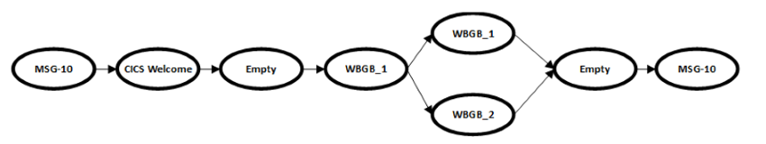
Although many screens here get unique names, some screens are the same screen, for example, "MSG-10" and "MSG-10_1". You should rename the WBGB_1 and WBGB_2 to something more informative. For a repeated screen, use only one instance for that screen in your plan. Here are examples that show how a standalone plan, Connect plan, Disconnect plan, and a combined plan might look:
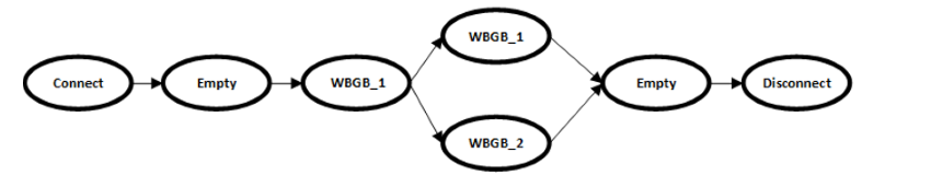
Standalone plan
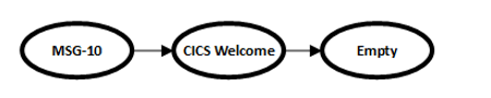
Connect plan
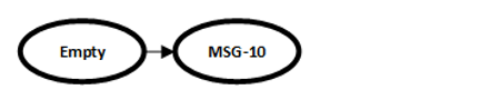
Disconnect plan
Combined plan
Example: Identify repeated screens
The example plan has a fork where you can get screens that look similar. One screen returns an account balance, while the other screen returns an error message.
The design tool lets you add recognition attributes, for example, a screen title named "Get Account Balance", by using the Screen Recognition editor. In the case with similar screens, you need other attributes. At run time, the connector uses these attributes for determining the branch and fork.
In the branch that returns valid input, which is the screen with the account balance, you can add a field that has a "not empty" condition.
In the branch that returns with an error, you can add a field that has an "empty" condition.
Define methods
In this mode, you define a method that's associated with your navigation plan. For each method parameter, you specify the data type, such as a string, integer, date or time, and so on. When you're done, you can test your method on the live host and confirm that the method works as expected. You then generate the metadata file, or Host Integration Designer XML (HIDX) file, which now has the method definitions to use for creating and running an action for the IBM 3270 connector. It also generates C# classes for Host Integration Server. You can also generate C# classes for use with Host Integration Server.
On the 3270 Design Tool's toolbar, select Methods so that you enter Methods mode.
In the Methods pane, select the New Method button. Enter a name for the new method. Select OK.
In the Navigation pane, select the screen that has the input fields you want.
To add the first input parameter for your method, follow these steps:
In the Capture pane, on the 3270 emulator screen, select the whole field, not just text inside the field, that you want as the first input.
Tip
To display all the fields and make sure that you select the complete field, on the View menu, select All Fields.
On the design tool's toolbar, select Input Field.
To add more input parameters, repeat the previous steps for each parameter. Refer to the previus steps.
To add the first output parameter for your method, follow these steps:
In the Capture pane, on the 3270 emulator screen, select the whole field, not just text inside the field, that you want as the first output.
Tip
To display all the fields and make sure that you select the complete field, on the View menu, select All Fields.
On the design tool's toolbar, select Output Field.
To add more output parameters, repeat the previous steps for each parameter.
After you add all your method's parameters, define these properties for each parameter:
Property name Possible values Data Type Byte, Date Time, Decimal, Int, Long, Short, String Field Fill Technique Parameters support these fill types, filling with blanks if necessary: - Type: Enter characters sequentially into the field.
- Fill: Replace the field's contents with characters, filling with blanks if necessary.
- EraseEofType: Clear the field, and then enter characters sequentially into the field.
Format String Some parameter data types use a format string, which informs the 3270 connector how to convert text from the screen into a .NET data type: - DateTime: The DateTime format string follows the .NET custom date and time format strings. For example, the date
06/30/2019uses the format stringMM/dd/yyyy.- Decimal: The decimal format string uses the COBOL Picture clause. For example, the number
100.35uses the format string999V99.
Save and view metadata
After you define your method, but before you test your method, save all the information that you defined so far to a RAP (.rap) file. You can save to this RAP file at any time during any mode. The design tool also includes a sample RAP file that you can open and review by browsing to the design tool's installation folder at this location and opening the "WoodgroveBank.rap" file:
..\Program Files\Microsoft Host Integration Server - 3270 Design Tool\SDK\WoodgroveBank.rap
However, if you try saving changes to the sample RAP file or generating an HIDX file from the sample RAP file while the file stays in the design tool's installation folder, you might get an "access denied" error. By default, the design tool installs in your Program Files folder without elevated permissions. If you get an error, try one of these solutions:
- Copy the sample file to a different location.
- Run the design tool as an administrator.
- Make yourself the owner for the SDK folder.
Test your method
To run your method against the live host, while still in Methods mode, press the F5 key, or from the design tool's toolbar, select Test.
Tip
You can change modes at any time. On the File menu, select Tools, and then select the mode you want: Use Minimal Progress Form and Chain Methods
Enter your parameters' values, and select OK.
To continue to the next screen, select Next.
When you're finished, select Done, which shows your output parameter values.
Generate and upload HIDX file
When you're ready, generate the HIDX file. The 3270 Design Tool creates the HIDX file in a new subfolder where you saved your RAP file. You can then upload the HIDX file to your integration account that's linked to a Consumption or Standard logic app resource. Or, you can upload directly to your Standard logic app resource through the Artifacts section under Maps on your resource menu.
In the 3270 Design Tool, from the Tools menu, select Generate Definitions. (Keyboard: F6)
Go to the folder that contains your RAP file, and open the subfolder that the tool created after generating your HIDX file. Confirm that the tool created the HIDX file.