Use Pixyz Studio to prepare 3D objects for use in Dynamics 365 Guides or in mixed-reality components used in apps created with Power Apps
This tutorial outlines a general process for using Pixyz Studio (2020.1 Update 2 r16) to convert Computer-Aided Design (CAD) parametric assets into polygon-based .GLB files that perform well in Microsoft Dynamics 365 Guides or in mixed-reality components used in apps created with Microsoft Power Apps. (See Optimize your 3D objects for information about performance targets.) Keep in mind that every asset and use case is different, so you might need to adjust the process accordingly.
Important
This document is created strictly for informative purposes to demonstrate how Pixyz Studio (2020.1 Update 2 r16) works with Dynamics 365 Guides or Power Apps. This document was last updated in November 2020. Your use of third-party applications is subject to terms between you and the third party. Microsoft Corporation is not affiliated with, is not a partner to, and does not endorse or sponsor Pixyz or any of Pixyz’s products. There are other content-creation apps you can use to prepare your 3D objects.
What is Pixyz Studio?
Pixyz Studio helps companies and 3D users reuse their CAD data for any visualization scenario.
Import a CAD asset into Pixyz Studio
Open Pixyz Studio, and then on the top-left side of the toolbar, select Wizard to start the Import wizard.

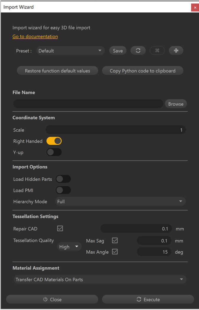
In the Import Wizard dialog box, use the following settings to create a high-quality tessellation as a starting point:
Field Value Subvalue Preset Default Coordinate System Right Handed: On Y-up: Off Import Options Load Hidden Parts: Off Load PMI: Off Hierarchy Mode: Full Tessellation Settings Repair CAD: On, 0.1 mm Tessellation Quality, High Max Sag: On, 0.1 mm Max Angle: On, 15 deg Material Assignment Transfer CAD Materials On Parts 
Select Execute.
Scene cleanup
Start by manually removing all parts and assemblies that aren't required for the mixed-reality app.
In the Viewer or the Product Structure (Tree), select Occurrences.
Press Delete on the keyboard to delete the selection from the scene.
Note
Tools in the Selection menu such as Select Instances, Select Similar, and Select By Max Size can be very useful for quickly selecting multiple occurrences to delete.
After removing all the unnecessary parts and assemblies, you can use the following commands to clean up leftover occurrences, materials, textures, and lines:
• Scene > Delete Empty Occurrences
• Materials > Clean Unused Materials
• Materials > Clean Unused Textures
• Mesh > Delete Lines
Note
If lines are important for your scenario, you can use Mesh > Create Textures From Lines on co-planar lines to bake a textured polygon to use in mixed-reality apps. See the Pixyz documentation for more information.
Remove features
If there are holes in any of the parts or assemblies that aren’t required for your scenario, you can remove them for potentially large polygon savings.
Select the parts and assemblies that have the holes you want to remove.
Note
If you don’t make a selection, Pixyz runs the Remove Holes command on the entire scene.
Select Optimize Mesh > Remove Holes.
In the Remove Holes window, select the types of holes you want to remove:
Through Holes: Holes that go through a surface and come out the other side.
Blind Holes: Holes that go into a surface but stop part way through.
Surfacic Holes: Holes that are cut into a surface but don’t have any depth.

Enter a number (in millimeters) for the Max Diameter field. Holes with a diameter below this value that match the types you set will be removed.
Optionally, select the Fill With Material check box to select a material to fill holes. This leaves the appearance of a hole but provides better performance due to the reduction in polygons.
Hierarchy cleanup
At this point, consider whether you need to break up objects into pieces to export as separate .GLB files for animation purposes or for progressively hiding/showing in mixed-reality apps.
Select the parts and assemblies that you want to merge.
Select Scene > Merge Parts to combine them into a single occurrence.
Select Scene > Delete Empty Occurrences to remove any occurrences left behind in the merge process.
Select Scene > Rake Tree to flatten the hierarchy down to a root node. Any remaining occurrences in the scene are children.
Tip
These additional merge operations on the Scene menu might also be useful depending on your scenario:
Merge Final Level
Merge By Tree Level
Merge Parts By Assemblies
Merge Parts By Name
Merge Parts By Materials
Optimize your mesh
To fully optimize your mesh, start by using the Hidden Removal command, and then based on your scenario, use the Decimate to Quality or Decimate to Target command.
Hidden Removal command
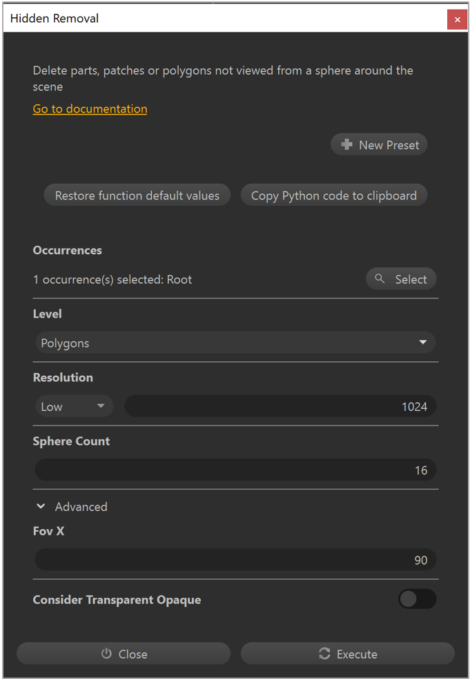
Use the Hidden Removal command to do a visibility test to determine which polygons can be removed without affecting the look of the model.
Select Optimize Mesh > Hidden Removal.
In the Level field, select Polygons.

Set the Resolution field to Low. This setting is sufficient for most assets. However, if the asset contains many important small details, consider increasing it to Medium or High.
Select Execute.
Note
If you have determined that your asset requires multiple pieces, hide the overlapping pieces before using the Hidden Removal command to prevent creating holes in adjacent pieces.
Decimate to Quality command
Use the Decimate to Quality command to reduce polygons based on a perceived quality target. Consider how each piece of the asset will be used in mixed reality:
Is it the focus of the mixed-reality experience?
Are the fine details important to convey the information in mixed reality?
Is it for context or supporting visuals?
To use the Decimate to Quality command:
Select the piece you want to optimize.
Select Optimize Mesh > Decimate To Quality.
In the Decimate window, in the Preset field, select Medium.

Set the Surfacic Tolerance field to 1mm.
Select Execute.
Note
The above settings provide a good balance of quality and polygon reduction for most assets. Use the Low preset when details are important, or the piece is the focus of the mixed-reality experience. The Strong preset works well for supporting visuals.
Decimate to Target command
If you have a specific polygon count that you’re aiming for, the Decimate To Target command is a good alternative to the Decimate To Quality command.
Select the piece that you want to optimize.
Select Optimize Mesh > Decimate To Target.
In the Target Triangle Count field, enter the number of triangles that you’re targeting.

Select Execute.
Note
If you don’t make any selection, the Decimate to Target command applies to the entire scene.
Reduce draw calls
In addition to reducing polygon count and hierarchy complexity, draw calls should be minimized to ensure good performance at runtime. Materials with different colors and surface qualities can be baked into texture maps so that complex objects can be rendered in a single draw call. You can do this by creating UVs, normals and tangents, baking texture maps, creating a new material based on the texture bakes, and finally, by applying the new material.
Important
You need to use all of the commands in this section to reduce draw calls.
UV generation
Select a piece from your scene.
Select UVs > Generate UV By Unwrapping.
In the Automatic UV Mapping window, set the Channel field to 0 (the primary UV set).

Move the Forbid Overlapping toggle to the On position to create a unique UV unwrap, which is required for texture baking.
Select Execute.
Note
Turn on Checker on the top toolbar to visualize the results of the UV unwrap in the Viewer. Select UVs > UV Viewer to see the UV layout.
Create normals and tangents
Normals and tangents are required for final model rendering as well as for the texture-baking process. Do all of the following steps, in order, to create normals and tangents:
Select a piece that already has a UV layout.
Select Mesh > Create Normals.
Select Mesh > Orient Normals.
Select Mesh > Create Tangents.
Bake texture maps
After generating UVs and creating normals and tangents, you can bake the textures.
Select a piece that already has UVs, normals, and tangents.
Select Optimize Mesh > Bake Texture Maps.
In the Bake Maps window, select the + button to add a texture map.
In the Maps to Bake list, select Diffuse.

Repeat steps 3 and 4, as necessary, for any more texture maps.
Set the Channel field to 0 to use the primary UV set for baking textures.
Set the Resolution field to 2048 to bake high-resolution textures for detailed pieces.
Select Execute.
Note
You can use a texture resolution of 1024 or 512 on simple objects to keep the runtime memory usage and final .GLB file size to a minimum.
Create and apply materials
You need to apply baked texture maps to a Physically Based Rendering (PBR) material, which can then be applied to the asset for glTF-compliant rendering in mixed-reality apps.
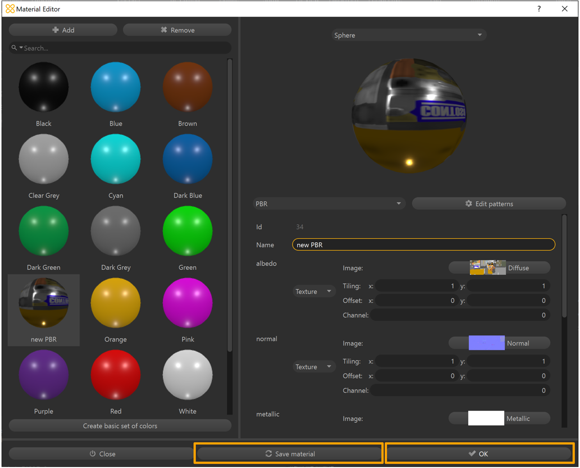
Select Materials > Material Editor.
Select Add.
In the Choose a material pattern list, select PBR.
Select OK.

Enter a Name for the material.
Next to albedo, select the Color list and change it to Texture.
In the Image field, select Undefined.

In the Texture Library window, select the baked Diffuse texture map.
Select the Select button to confirm the texture selection.

Repeat steps 6-9, as necessary, for any other texture maps.
Select Save material to add it to the material library of the scene.

Select OK to close the Material Editor window.
Select the piece you want to apply the material to.
On the Inspector tab, under Occurrence Properties, select the No Material button. (Ignore the materials in the Occurrence Components section.)

In the Material selector window, select the new material.
Select Apply.

Export the model to a GLB file
At this point, you have a fully optimized model that’s ready to export as a .GLB file for use in Dynamics 365 mixed-reality apps.
Select the piece you want to export.
Select File > Export Selection.
Select a location on your device where you want to export your file.
Enter a name for the file.
Select GLTF Binary (*.glb) as the file type.

Select Save.
Repeat steps 1-6, as necessary, to export multiple pieces to .GLB files.
On the toolbar, select Export.
Note
If nothing is selected, the entire scene will be exported to a single .GLB file.
Preview an exported GLB file
You can preview the resulting .GLB file(s) with the 3D Viewer on Windows, where you can visualize the individual texture channels and view stats such as triangle count and draw calls to confirm the asset exported as expected.
Open 3D Viewer.
Drag and drop a .GLB file into the viewport (or select File > Open to browse for a .GLB file).
Select the Stats & Shading tab on the right side of the screen to start visualizing different components of the .GLB file.
Use the check boxes to turn the different viewport visualizations on or off.
If your device has a camera, you can move the Mixed reality slider to the On position and place the asset to preview it in your world.

Tip
The Babylon.JS Web Viewer is another great option if uploading the asset is not a concern.
If the asset requires any more editing or animation work in another staging application, consider using .FBX as an intermediate file format. FBX is an Autodesk exchange format designed to preserve more authoring data that might be required by your staging application.
View a 3D object in a Dynamics 365 mixed-reality app
After preparing your 3D objects, you can learn more about using the following Dynamics 365 apps to view your 3D objects in mixed reality:
More information
Several screenshots in this document were taken from the Pixyz Studio (2020.1 Update 2 r16) software program to provide clear instructions on how to use Pixyz’s software. Learn more about Pixyz Studio.
Your use of any third-party application is subject to terms between you and the third party. Microsoft Corporation isn't affiliated with, isn't a partner to, and doesn't endorse or sponsor Pixyz or any of Pixyz’s products. Microsoft Corporation isn't responsible for, and expressly disclaims all liability for damages of any kind arising out of the use of Pixyz Studio, or reliance on these instructions. This document is created only to provide general information to our customers and doesn't take into consideration any individualized business plans or specifications or updates to Pixyz Studio that may have been made after the date the tutorial was prepared.
The use in this document of trademarked names and images is strictly to attribute the application to Pixyz Studio and for informative and descriptive purposes, and no commercial claim to their use, or suggestion of sponsorship or endorsement, is made by Microsoft.