Virtual appliance scenario
A common scenario among larger Azure customers is the need to provide a two-tiered application that's exposed to the internet while it also allows access to the back tier from an on-premises datacenter. This article walks you through a scenario that uses route tables, a VPN gateway, and network virtual appliances to deploy a two-tiered environment that meets the following requirements:
- A web application must be accessible from the public internet only.
- A web server that hosts the application must be able to access a back-end application server.
- All traffic from the internet to the web application must go through a firewall virtual appliance. This virtual appliance is used for internet traffic only.
- All traffic that goes to the application server must go through a firewall virtual appliance. This virtual appliance is used for access to the back-end server, and for access coming in from the on-premises network via a VPN gateway.
- Administrators must be able to manage the firewall virtual appliances from their on-premises computers by using a third firewall virtual appliance that's used exclusively for management purposes.
This example is a standard perimeter network (also known as DMZ) scenario with a DMZ and a protected network. You can construct this scenario in Azure by using network security groups (NSGs), firewall virtual appliances, or a combination of both.
The following table shows some of the pros and cons for NSGs and firewall virtual appliances.
| Item | Pros | Cons |
|---|---|---|
| NSG | No cost. Integrated into Azure role-based access. Ability to create rules in Azure Resource Manager templates. |
Complexity could vary in larger environments. |
| Firewall | Full control over data plane. Central management through firewall console. |
Cost of firewall appliance. Not integrated with Azure role-based access. |
The following solution uses firewall virtual appliances to implement a perimeter network (DMZ)/protected network scenario.
Considerations
You can deploy the preceding environment in Azure by using features that are available today:
- Virtual network: An Azure virtual network acts in a similar fashion to an on-premises network. You can segment it into one or more subnets to provide traffic isolation and separation of concerns.
- Virtual appliance: Several partners provide virtual appliances in Azure Marketplace to use for the three firewalls described previously.
- Route tables: Route tables are used by Azure networking to control the flow of packets within a virtual network. You can apply these route tables to subnets. You can apply a route table to
GatewaySubnet, which forwards all traffic that enters into the Azure virtual network from a hybrid connection to a virtual appliance. - IP forwarding: By default, the Azure networking engine forwards packets to virtual network interface cards (NICs) only if the packet destination IP address matches the NIC IP address. If a route table defines that a packet must be sent to a specific virtual appliance, the Azure networking engine drops that packet. To ensure that the packet is delivered to a VM (in this case a virtual appliance) that isn't the actual destination for the packet, enable IP forwarding for the virtual appliance.
- Network security groups: The following example doesn't make use of NSGs, but you can use NSGs applied to the subnets or NICs in this solution. The NSGs further filter the traffic in and out of those subnets and NICs.
In this example, a subscription contains the following items:
Two resource groups (not shown in the diagram):
ONPREMRG: Contains all resources necessary to simulate an on-premises network.AZURERG: Contains all resources necessary for the Azure virtual network environment.
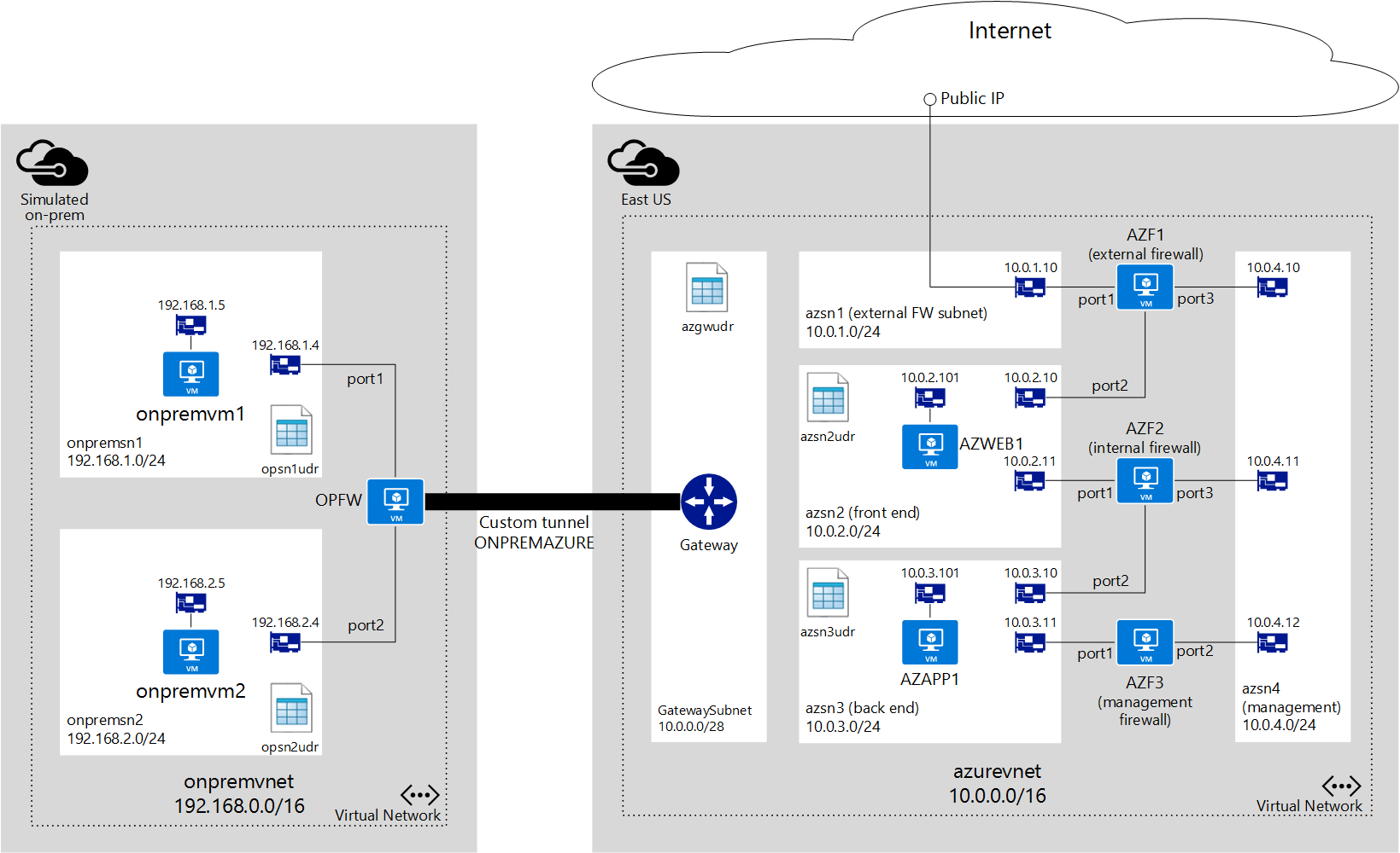
A virtual network named
onpremvnetis segmented and used to mimic an on-premises datacenter:onpremsn1: A subnet that contains a virtual machine (VM) running a Linux distribution to mimic an on-premises server.onpremsn2: A subnet that contains a VM running a Linux distribution to mimic an on-premises computer used by an administrator.
One firewall virtual appliance is named
OPFWononpremvnet. It's used to maintain a tunnel toazurevnet.A virtual network named
azurevnetis segmented as follows:azsn1: An external firewall subnet used exclusively for the external firewall. All internet traffic comes in through this subnet. This subnet contains only a NIC linked to the external firewall.azsn2: A front-end subnet that hosts a VM running as a web server that's accessed from the internet.azsn3: A back-end subnet that hosts a VM running a back-end application server accessed by the front-end web server.azsn4: A management subnet used exclusively to provide management access to all firewall virtual appliances. This subnet contains only a NIC for each firewall virtual appliance used in the solution.GatewaySubnet: An Azure hybrid connection subnet that's required for Azure ExpressRoute and Azure VPN Gateway to provide connectivity between Azure virtual networks and other networks.
Three firewall virtual appliances are in the
azurevnetnetwork:AZF1: An external firewall exposed to the public internet by using a public IP address resource in Azure. You need to ensure that you have a template from Azure Marketplace or directly from your appliance vendor that deploys a three-NIC virtual appliance.AZF2: An internal firewall used to control traffic betweenazsn2andazsn3. This firewall is also a three-NIC virtual appliance.AZF3: A management firewall accessible to administrators from the on-premises datacenter and connected to a management subnet that's used to manage all firewall appliances. You can find two-NIC virtual appliance templates in Azure Marketplace. You can also request one directly from your appliance vendor.
Route tables
Link each subnet in Azure to a route table to define how traffic initiated in that subnet is routed. If no user-defined routes (UDRs) are defined, Azure uses default routes to allow traffic to flow from one subnet to another. To better understand route tables and traffic routing, see Azure virtual network traffic routing.
To ensure that communication is done through the proper firewall appliance, based on the last requirement listed previously, you must create the following route table in azurevnet.
azgwudr
In this scenario, the only traffic that flows from on-premises to Azure is used to manage the firewalls by connecting to AZF3, and that traffic must go through the internal firewall, AZF2. Only one route is necessary in GatewaySubnet, as shown here:
| Destination | Next hop | Explanation |
|---|---|---|
| 10.0.4.0/24 | 10.0.3.11 | Allows on-premises traffic to reach management firewall AZF3. |
azsn2udr
| Destination | Next hop | Explanation |
|---|---|---|
| 10.0.3.0/24 | 10.0.2.11 | Allows traffic to the back-end subnet that hosts the application server through AZF2. |
| 0.0.0.0/0 | 10.0.2.10 | Allows all other traffic to be routed through AZF1. |
azsn3udr
| Destination | Next hop | Explanation |
|---|---|---|
| 10.0.2.0/24 | 10.0.3.10 | Allows traffic to azsn2 to flow from an app server to the web server through AZF2. |
You also need to create route tables for the subnets in onpremvnet to mimic the on-premises datacenter.
onpremsn1udr
| Destination | Next hop | Explanation |
|---|---|---|
| 192.168.2.0/24 | 192.168.1.4 | Allows traffic to onpremsn2 through OPFW. |
onpremsn2udr
| Destination | Next hop | Explanation |
|---|---|---|
| 10.0.3.0/24 | 192.168.2.4 | Allows traffic to the back-end subnet in Azure through OPFW. |
| 192.168.1.0/24 | 192.168.2.4 | Allows traffic to onpremsn1 through OPFW. |
IP forwarding
Route tables and IP forwarding are features that you can use in combination to allow virtual appliances to control traffic flow in an Azure virtual network. A virtual appliance is nothing more than a VM that runs an application used to handle network traffic in some way, such as a firewall or a network address translation device.
This virtual appliance VM must be able to receive incoming traffic that isn't addressed to itself. To allow a VM to receive traffic addressed to other destinations, you must enable IP forwarding for the VM. This setting is an Azure setting, not a setting in the guest operating system. Your virtual appliance still needs to run some type of application to handle the incoming traffic and route it appropriately.
To learn more about IP forwarding, see Azure virtual network traffic routing.
As an example, imagine that you have the following setup in an Azure virtual network:
- Subnet
onpremsn1contains a VM namedonpremvm1. - Subnet
onpremsn2contains a VM namedonpremvm2. - A virtual appliance named
OPFWis connected toonpremsn1andonpremsn2. - A UDR linked to
onpremsn1specifies that all traffic toonpremsn2must be sent toOPFW.
At this point, if onpremvm1 tries to establish a connection with onpremvm2, the UDR is used, and traffic is sent to OPFW as the next hop. The actual packet destination isn't being changed. It still says that onpremvm2 is the destination.
Without IP forwarding enabled for OPFW, the Azure virtual networking logic drops the packets because it allows only packets to be sent to a VM if the VM's IP address is the destination for the packet.
With IP forwarding, the Azure virtual network logic forwards the packets to OPFW, without changing its original destination address. OPFW must handle the packets and determine what to do with them.
For the previous scenario to work, you must enable IP forwarding on the NICs for OPFW, AZF1, AZF2, and AZF3 that are used for routing (all NICs except the ones linked to the management subnet).
Firewall rules
As described previously, IP forwarding only ensures that packets are sent to the virtual appliances. Your appliance still needs to decide what to do with those packets. In the previous scenario, you need to create the following rules in your appliances.
OPFW
OPFW represents an on-premises device that contains the following rules:
- Route: All traffic to 10.0.0.0/16 (
azurevnet) must be sent through the tunnelONPREMAZURE. - Policy: Allow all bidirectional traffic between
port2andONPREMAZURE.
AZF1
AZF1 represents an Azure virtual appliance that contains the following rule:
Policy: Allow all bidirectional traffic between port1 and port2.
AZF2
AZF2 represents an Azure virtual appliance that contains the following rule:
Policy: Allow all bidirectional traffic between port1 and port2.
AZF3
AZF3 represents an Azure virtual appliance that contains the following rule:
Route: All traffic to 192.168.0.0/16 (onpremvnet) must be sent to the Azure gateway IP address (that is, 10.0.0.1) through port1.
Network security groups
In this scenario, NSGs aren't being used. However, you can apply NSGs to each subnet to restrict incoming and outgoing traffic. For instance, you can apply the following NSG rules to the external firewall subnet.
Incoming
- Allow all TCP traffic from the internet to port 80 on any VM in the subnet.
- Deny all other traffic from the internet.
Outgoing
Deny all traffic to the internet.
High-level steps
To deploy this scenario, follow these steps:
Sign in to your Azure subscription.
If you want to deploy a virtual network to mimic the on-premises network, deploy the resources that are part of
ONPREMRG.Deploy the resources that are part of
AZURERG.Deploy the tunnel from
onpremvnettoazurevnet.After all resources are provisioned, sign in to
onpremvm2and ping 10.0.3.101 to test connectivity betweenonpremsn2andazsn3.