Projection transform
A projection transformation controls the camera's internals, like choosing a lens for a camera. This is the most complicated of the three transformation types.
The projection matrix is typically a scale and perspective projection. The projection transformation converts the viewing frustum into a cuboid shape. Because the near end of the viewing frustum is smaller than the far end, this has the effect of expanding objects that are near to the camera; this is how perspective is applied to the scene.
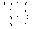
In the viewing frustum, the distance between the camera and the origin of the viewing transform space is defined arbitrarily as D, so the projection matrix looks like the following illustration.
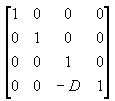
The viewing matrix translates the camera to the origin by translating in the z direction by - D. The translation matrix is like the following illustration.
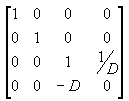
Multiplying the translation matrix by the projection matrix (T*P) gives the composite projection matrix, as shown in the following illustration.
The perspective transform converts a viewing frustum into a new coordinate space. Notice that the frustum becomes cuboid and also that the origin moves from the upper-right corner of the scene to the center, as shown in the following diagram.
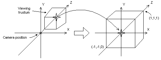
In the perspective transform, the limits of the x- and y-directions are -1 and 1. The limits of the z-direction are 0 for the front plane and 1 for the back plane.
This matrix translates and scales objects based on a specified distance from the camera to the near clipping plane, but it doesn't consider the field of view (fov), and the z-values that it produces for objects in the distance can be nearly identical, making depth comparisons difficult. The following matrix addresses these issues, and it adjusts vertices to account for the aspect ratio of the viewport, making it a good choice for the perspective projection.
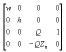
In this matrix, Zₙ is the z-value of the near clipping plane. The variables w, h, and Q have the following meanings. Note that fovw and fovₖ represent the viewport's horizontal and vertical fields of view, in radians.
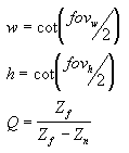
For your application, using field-of-view angles to define the x- and y-scaling coefficients might not be as convenient as using the viewport's horizontal and vertical dimensions (in camera space). As the math works out, the following two equations for w and h use the viewport's dimensions, and are equivalent to the preceding equations.

In these formulas, Zₙ represents the position of the near clipping plane, and the Vw and Vₕ variables represent the width and height of the viewport, in camera space.
Whatever formula you decide to use, be sure to set Zₙ to as large a value as possible, because z-values extremely close to the camera don't vary by much. This makes depth comparisons using 16-bit z-buffers somewhat complicated.
A w-friendly projection matrix
Direct3D can use the w-component of a vertex that has been transformed by the world, view, and projection matrices to perform depth-based calculations in depth-buffer or fog effects. Computations such as these require that your projection matrix normalize w to be equivalent to world-space z. In short, if your projection matrix includes a (3,4) coefficient that is not 1, you must scale all the coefficients by the inverse of the (3,4) coefficient to make a proper matrix. If you don't provide a compliant matrix, fog effects and depth buffering are not applied correctly.
The following illustration shows a noncompliant projection matrix, and the same matrix scaled so that eye-relative fog will be enabled.
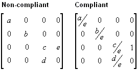
In the preceding matrices, all variables are assumed to be nonzero. For information about w-based depth buffering, see Depth buffers.
Direct3D uses the currently set projection matrix in its w-based depth calculations. As a result, applications must set a compliant projection matrix to receive the desired w-based features, even if they do not use Direct3D for transforms.
Related topics
คำติชม
เร็วๆ นี้: ตลอดปี 2024 เราจะขจัดปัญหา GitHub เพื่อเป็นกลไกคำติชมสำหรับเนื้อหา และแทนที่ด้วยระบบคำติชมใหม่ สำหรับข้อมูลเพิ่มเติม ให้ดู: https://aka.ms/ContentUserFeedback
ส่งและดูข้อคิดเห็นสำหรับ