How Azure Load Balancer works
Azure Load Balancer operates at the transport layer of the OSI model. This Layer 4 functionality allows traffic management based on specific properties of the traffic. Properties including, source and destination address, TCP or UDP protocol type, and port number.
Load Balancer has several elements that work together to ensure an application's high availability and performance:
- Front-end IP
- Load balancer rules
- Back-end pool
- Health probes
- Inbound NAT rules
- High availability ports
- Outbound rules
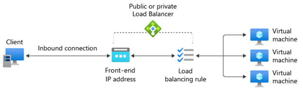
Front-end IP
The front-end IP address is the address clients use to connect to your web application. A front-end IP address can be either a public or a private IP address. Azure load balancers can have multiple front-end IPs. The selection of a public or a private IP address determines which type of load balancer to create:
Public IP address: A public load balancer: A public load balancer maps the public IP and port of incoming traffic to the private IP and port of the VM. You can distribute specific types of traffic across multiple VMs or services by applying load-balancing rules. For example, you can spread the load of web request traffic across multiple web servers. The load balancer maps the response traffic from the private IP and port of the VM to the public IP and port of the load balancer. Then, it transmits the response back to the requesting client.
Private IP address: An internal load balancer: An internal load balancer distributes traffic to resources that are inside a virtual network. Azure restricts access to the front-end IP addresses of a virtual network that are load balanced. Front-end IP addresses and virtual networks are never directly exposed to an internet endpoint. Internal line-of-business applications run in Azure and are accessed from within Azure or from on-premises resources through a VPN or ExpressRoute connection.
Load Balancer rules
A load balancer rule defines how traffic is distributed to the back-end pool. The rule maps a given front-end IP and port combination to a set of back-end IP addresses and port combination.
Traffic is managed using a five-tuple hash made from the following elements:
- Source IP: The IP address of the requesting client.
- Source port: The port of the requesting client.
- Destination IP: The destination IP address of the request.
- Destination port: The destination port of the request.
- Protocol type: The specified protocol type, TCP or UDP.
- Session affinity: Ensures that the same pool node always handles traffic for a client.
Load Balancer allows you to load balance services on multiple ports, multiple IP addresses, or both. You can configure different load balancing rules for each front-end IP. Multiple front-end configurations are only supported with IaaS VMs.
Load Balancer can't apply different rules based on internal traffic content because it operates at Layer 4 (transport layer) of the OSI model. If you need to manage traffic based on its Layer 7 (application layer) properties, you need to deploy a solution like Azure Application Gateway.
Back-end pool
The back-end pool is a group of VMs or instances in a Virtual Machine Scale Set that responds to the incoming request. To scale cost-effectively to meet high volumes of incoming traffic, computing guidelines generally recommend adding more instances to the back-end pool.
Load Balancer implements automatic reconfiguration to redistribute load across the altered number of instances when you scale instances up or down. For example, if you added two more VMs instances to the back-end pool, Load Balancer would reconfigure itself to start balancing traffic to those instances based on the already configured load balancing rules.
Health probes
A health probe is used to determine the health status of the instances in the back-end pool. This health probe determines if an instance is healthy and can receive traffic. You can define the unhealthy threshold for your health probes. When a probe fails to respond, the load balancer stops sending new connections to the unhealthy instances. A probe failure doesn't affect existing connections. The connection continues until:
- The application ends the flow.
- Idle timeout occurs.
- The VM shuts down.
Load Balancer allows you to configure different health probe types for endpoints: TCP, HTTP, and HTTPS.
- TCP custom probe: This probe relies on establishing a successful TCP session to a defined probe port. If the specified listener on the VM exists, the probe succeeds. If the connection is refused, the probe fails. You can specify the Port, Interval, and Unhealthy threshold.
- HTTP or HTTPS custom probe: The load balancer regularly probes your endpoint (every 15 seconds, by default). The instance is healthy if it responds with an HTTP 200 within the timeout period (default of 31 seconds). Any status other than HTTP 200 causes the probe to fail. You can specify the port (Port), the URI for requesting the health status from the back end (URI), amount of time between probe attempts (Interval), and the number of failures that must occur for the instance to be considered unhealthy (Unhealthy threshold).
Session persistence
By default, Load Balancer distributes network traffic equally among multiple VM instances. It provides stickiness only within a transport session. Session persistence specifies how traffic from a client should be handled. The default behavior (None) is that any healthy VM can handle successive requests from a client.
Session persistence is also known as session affinity, source IP affinity, or client IP affinity. This distribution mode uses a two-tuple (source IP and destination IP) or three-tuple (source IP, destination IP, and protocol type) hash to route to back-end instances. When you use session persistence, connections from the same client go to the same back-end instance within the back-end pool. You can configure one of the following session persistence options:
- None (default): Specifies that any healthy VM can handle the request.
- Client IP (2-tuple): Specifies that the same back-end instance can handle successive requests from the same client IP address.
- Client IP and protocol (3-tuple): Specifies that the same back-end instance can handle successive requests from the same client IP address and protocol combination.
You can change this behavior by configuring one of the options that are described in the following sections.
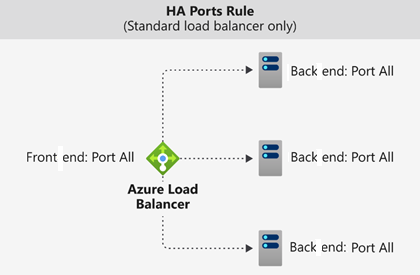
High availability ports
A load balancer rule configured with protocol - all and port - 0 is called a high availability (HA) port rule. This rule enables a single rule to load balance all TCP and UDP flows that arrive on all ports of an internal standard load balancer.
The load-balancing decision is made per flow. This action is based on the following five-tuple connection:
- Source IP address
- Source port
- Destination IP address
- Destination port
- Protocol
HA ports load-balancing rules help you with critical scenarios, such as high availability and scale for network virtual appliances (NVAs) inside virtual networks. The feature can help when a large number of ports must be load balanced.
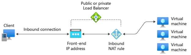
Inbound NAT rules
You can use load balancing rules in combination with Network Address Translation (NAT) rules. For example, you could use NAT from the load balancer's public address to TCP 3389 on a specific VM. This rule combination allows remote desktop access from outside of Azure.
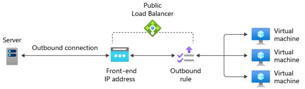
Outbound rules
An outbound rule configures Source Network Address Translation (SNAT) for all VMs or instances identified by the back-end pool. This rule enables instances in the back end to communicate (outbound) to the internet or other public endpoints.