你当前正在访问 Microsoft Azure Global Edition 技术文档网站。 如果需要访问由世纪互联运营的 Microsoft Azure 中国技术文档网站,请访问 https://docs.azure.cn。
本文帮助你通过 ExpressRoute 专用连接在本地网络与 Azure 虚拟网络 (VNet) 间配置安全的加密连接。 可使用 Microsoft 对等互连在所选本地网络和 Azure VNet 间建立站点到站点的 IPsec/IKE VPN 隧道。 通过 ExpressRoute 配置安全隧道,即可机密、真实、完整地交换数据,不会出现重播。
备注
通过 Microsoft 对等互连设置站点到站点 VPN 时,需为 VPN 网关和 VPN 出口付费。 有关详细信息,请参阅 VPN 网关定价。
本文中的步骤和示例使用 Azure PowerShell Az 模块。 若要在计算机上本地安装 Az 模块,请参阅安装 Azure PowerShell。 若要详细了解新 Az 模块,请参阅新 Azure Powershell Az 模块简介。 PowerShell cmdlet 经常更新。 如果未运行最新版本,在说明中指定的值可能无法使用。 若要在系统上查找已安装的 PowerShell 版本,请使用 Get-Module -ListAvailable Az cmdlet。
体系结构
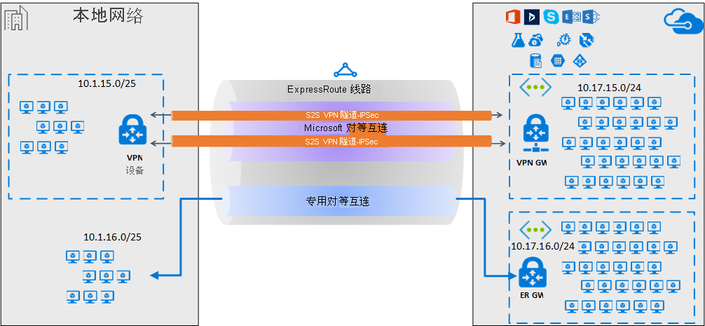
为获得高可用性和冗余,可通过 ExpressRoute 线路的两个 MSEE-PE 对配置多条隧道,并在隧道间启用负载均衡。
终止通过 Microsoft 对等互连配置的 VPN 隧道有两种方法:使用 VPN 网关;使用 Azure 市场提供的合适的网络虚拟设备 (NVA)。 可通过加密隧道静态或动态地交换路由,无需向底层 Microsoft 对等互连公开路由交换。 在本文的示例中,BGP(与用于创建 Microsoft 对等互连的 BGP 会话不同)用于在加密隧道上动态交换前缀。
重要
对于本地端,通常会在 DMZ 上终止 Microsoft 对等互连,在核心网络区域终止专用对等互连。 两个区域使用防火墙分隔。 如果将 Microsoft 对等互连配置为专用于启用通过 ExpressRoute 配置的安全隧道,请记住只筛选相关的公共 IP,这些 IP 通过 Microsoft 对等互连播发。
工作流
- 为 ExpressRoute 线路配置 Microsoft 对等互连。
- 通过 Microsoft 对等互连将选定 Azure 区域公共前缀播发到本地网络。
- 配置 VPN 网关,建立 IPsec 隧道
- 配置本地 VPN 设备。
- 创建站点到站点的 IPsec/IKE 连接。
- (可选)在本地 VPN 设备上配置防火墙/筛选器。
- 通过 ExpressRoute 线路测试和验证 IPsec 通信。
1. 配置 Microsoft 对等互连
要通过 ExpressRoute 配置站点到站点 VPN 连接,必须使用 ExpressRoute Microsoft 对等互连。
要配置新的 ExpressRoute 线路,请先查看 ExpressRoute 先决条件一文,然后查看创建和修改 ExpressRoute 线路。
如果已有 ExpressRoute 线路,但未配置 Microsoft 对等互连,请查看创建和修改 ExpressRoute 线路的对等互连一文,配置 Microsoft 对等互连。
配置线路和 Microsoft 对等互连后,可以使用 Azure 门户的“概述”页面轻松查看它。
2. 配置路由筛选器
使用路由筛选器可标识要通过 ExpressRoute 线路的 Microsoft 对等互连使用的服务。 它实质上是所有 BGP 社区值的允许列表。
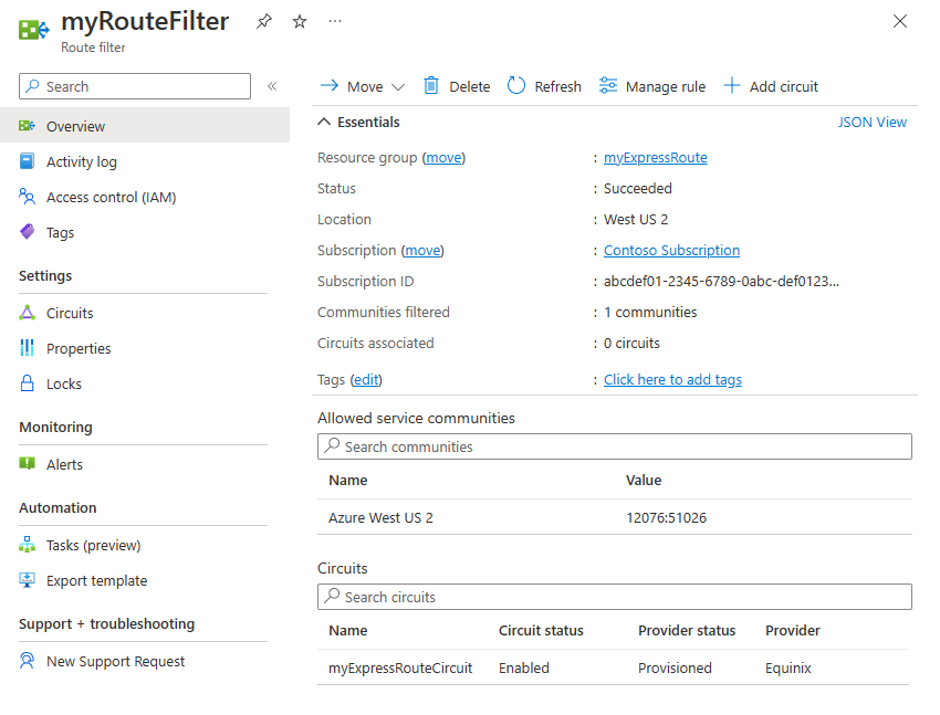
在此示例中,部署仅位于 Azure 美国西部 2 区域。 添加路由筛选器规则,仅允许 Azure 美国西部 2 区域前缀的播发,其 BGP 社区值为 12076:51026。 可选择“管理规则”来指定要允许的区域前缀。
在路由筛选器中,还需选择路由筛选器适用的 ExpressRoute 线路。 可通过选择“添加线路”来选择 ExpressRoute 线路。 在上图中,路由筛选器与示例 ExpressRoute 线路相关联。
2.1 配置路由筛选器
配置路由筛选器。 有关步骤,请参阅配置用于 Microsoft 对等互连的路由筛选器。
2.2 验证 BGP 路由
通过 ExpressRoute 线路成功创建 Microsoft 对等互连并将路由筛选器与线路关联后,可验证与 MSEE 对等互连的 PE 设备上 Microsoft Enterpise Edge (MSEE) 收到的 BGP 路由。 验证命令会有所不同,具体取决于 PE 设备的操作系统。
Cisco 示例
本示例使用 Cisco IOS-XE 命令。 该示例使用虚拟路由和转发 (VRF) 实例来隔离对等互连流量。
show ip bgp vpnv4 vrf 10 summary
以下部分输出显示从自治系统编号 (ASN) 为 12076 (MSEE) 的邻域 *.243.229.34 收到 68 个前缀:
...

Neighbor        V           AS MsgRcvd MsgSent   TblVer  InQ OutQ Up/Down  State/PfxRcd
X.243.229.34    4        12076   17671   17650    25228    0    0 1w4d           68
要查看从邻域收到的前缀列表,请使用以下示例:
sh ip bgp vpnv4 vrf 10 neighbors X.243.229.34 received-routes
要确认正在接收的前缀集是否正确,可进行交叉验证。 以下 Azure PowerShell 命令输出列出了通过 Microsoft 对等互连播发的每个服务和每个 Azure 区域的前缀:
Get-AzBgpServiceCommunity
3. 配置 VPN 网关和 IPsec 隧道
本节将在 Azure VPN 网关和本地 VPN 设备间创建 IPsec VPN 隧道。 这些示例使用 Cisco 云服务路由器 (CSR1000) VPN 设备。
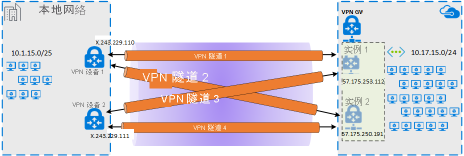
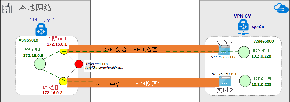
下图显示了在本地 VPN 设备 1 和 Azure VPN 网关实例对间建立的 IPsec VPN 隧道。 图中未显示在本地 VPN 设备 2 和 Azure VPN 网关实例对间建立的两条 IPsec VPN 隧道。 未列出配置详细信息。 但配置更多的 VPN 隧道可增强高可用性。
通过 IPsec 隧道对建立 eBGP 会话,交换专用网络路由。 下图显示了通过 IPsec 隧道对建立的 eBGP 会话:
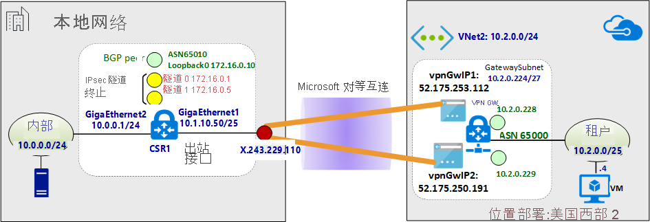
下图显示了示例网络的简要概述:
关于 Azure 资源管理器模板示例
这些示例使用 Azure 资源管理器模板配置 VPN 网关和 IPsec 隧道终端。 如果不熟悉资源管理器模板的用法或不了解资源管理器模板的基础知识,请参阅了解 Azure 资源管理器模板的结构和语法。 本部分中的模板会创建一个绿地 Azure 环境(虚拟网络)。 但如果已有现有的虚拟网络,则可在模板中引用它。 如果不熟悉 VPN 网关 IPsec/IKE 站点到站点配置,请参阅创建站点到站点连接。
注意
无需使用 Azure 资源管理器模板来创建此配置。 可使用 Azure 门户或 PowerShell 创建此配置。
3.1 声明变量
在此示例中,变量声明对应于示例网络。 声明变量时,请修改此部分以反映你的环境。
- 变量 localAddressPrefix 是本地 IP 地址的数组,用于终止 IPsec 隧道。
- gatewaySku 决定 VPN 吞吐量。 有关 gatewaySku 和 vpnType 的详细信息,请参阅 VPN 网关配置设置。 有关定价问题,请参阅 VPN 网关定价。
- 将 vpnType 设置为 RouteBased。
"variables": {
  "virtualNetworkName": "SecureVNet",       // Name of the Azure VNet
  "azureVNetAddressPrefix": "10.2.0.0/24",  // Address space assigned to the VNet
  "subnetName": "Tenant",                   // subnet name in which tenants exists
  "subnetPrefix": "10.2.0.0/25",            // address space of the tenant subnet
  "gatewaySubnetPrefix": "10.2.0.224/27",   // address space of the gateway subnet
  "localGatewayName": "localGW1",           // name of remote gateway (on-premises)
  "localGatewayIpAddress": "X.243.229.110", // public IP address of the on-premises VPN device
  "localAddressPrefix": [
    "172.16.0.1/32",                        // termination of IPsec tunnel-1 on-premises
    "172.16.0.2/32"                         // termination of IPsec tunnel-2 on-premises
  ],
  "gatewayPublicIPName1": "vpnGwVIP1",    // Public address name of the first VPN gateway instance
  "gatewayPublicIPName2": "vpnGwVIP2",    // Public address name of the second VPN gateway instance
  "gatewayName": "vpnGw",                 // Name of the Azure VPN gateway
  "gatewaySku": "VpnGw1",                 // Azure VPN gateway SKU
  "vpnType": "RouteBased",                // type of VPN gateway
  "sharedKey": "string",                  // shared secret needs to match with on-premises configuration
  "asnVpnGateway": 65000,                 // BGP Autonomous System number assigned to the VPN Gateway
  "asnRemote": 65010,                     // BGP Autonomous System number assigned to the on-premises device
  "bgpPeeringAddress": "172.16.0.3",      // IP address of the remote BGP peer on-premises
  "connectionName": "vpn2local1",
  "vnetID": "[resourceId('Microsoft.Network/virtualNetworks', variables('virtualNetworkName'))]",
  "gatewaySubnetRef": "[concat(variables('vnetID'),'/subnets/','GatewaySubnet')]",
  "subnetRef": "[concat(variables('vnetID'),'/subnets/',variables('subnetName'))]",
  "api-version": "2017-06-01"
},
3.2 创建虚拟网络(虚拟网络)
如果要将现有虚拟网络与 VPN 隧道关联,则可跳过此步骤。
{
  "apiVersion": "[variables('api-version')]",
  "type": "Microsoft.Network/virtualNetworks",
  "name": "[variables('virtualNetworkName')]",
  "location": "[resourceGroup().location]",
  "properties": {
    "addressSpace": {
      "addressPrefixes": [
        "[variables('azureVNetAddressPrefix')]"
      ]
    },
    "subnets": [
      {
        "name": "[variables('subnetName')]",
        "properties": {
          "addressPrefix": "[variables('subnetPrefix')]"
        }
      },
      {
        "name": "GatewaySubnet",
        "properties": {
          "addressPrefix": "[variables('gatewaySubnetPrefix')]"
        }
      }
    ]
  },
  "comments": "Create a Virtual Network with Subnet1 and Gatewaysubnet"
},
3.3 将公共 IP 地址分配到 VPN 网关实例
为每个 VPN 网关实例分配一个公共 IP 地址。
{
  "apiVersion": "[variables('api-version')]",
  "type": "Microsoft.Network/publicIPAddresses",
    "name": "[variables('gatewayPublicIPName1')]",
    "location": "[resourceGroup().location]",
    "properties": {
      "publicIPAllocationMethod": "Static"
    },
    "comments": "Public IP for the first instance of the VPN gateway"
  },
  {
    "apiVersion": "[variables('api-version')]",
    "type": "Microsoft.Network/publicIPAddresses",
    "name": "[variables('gatewayPublicIPName2')]",
    "location": "[resourceGroup().location]",
    "properties": {
      "publicIPAllocationMethod": "Static"
    },
    "comments": "Public IP for the second instance of the VPN gateway"
  },
3.4 指定本地 VPN 隧道终端(本地网关)
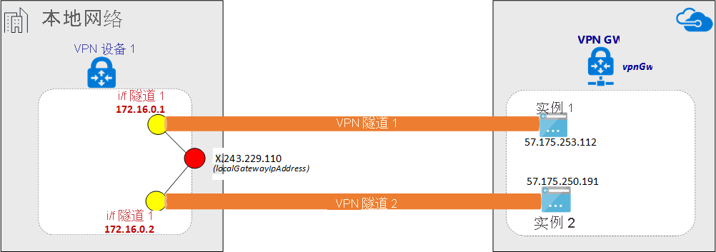
本地 VPN 设备被称为本地网关。 以下 json 片段还指定了远程 BGP 对等节点的详细信息:
{
  "apiVersion": "[variables('api-version')]",
  "type": "Microsoft.Network/localNetworkGateways",
  "name": "[variables('localGatewayName')]",
  "location": "[resourceGroup().location]",
  "properties": {
    "localNetworkAddressSpace": {
      "addressPrefixes": "[variables('localAddressPrefix')]"
    },
    "gatewayIpAddress": "[variables('localGatewayIpAddress')]",
    "bgpSettings": {
      "asn": "[variables('asnRemote')]",
      "bgpPeeringAddress": "[variables('bgpPeeringAddress')]",
      "peerWeight": 0
    }
  },
  "comments": "Local Network Gateway (referred to your on-premises location) with IP address of remote tunnel peering and IP address of remote BGP peer"
},
3.5 创建 VPN 网关
模板的这一部分使用主动/主动配置所需的设置来配置 VPN 网关。 请注意以下几个要求:
- 使用“RouteBased”VpnType 创建 VPN 网关。 若要启用 VPN 网关与本地 VPN 间的 BGP 路由,则此设置是必需的。
- 为了在主动/主动模式下,在 VPN 网关的两个实例和给定在本地设备间建立 VPN 隧道,需将资源管理器模板中的“activeActive”参数设置为 true。 要详细了解高可用 VPN 网关,请参阅高可用 VPN 网关连接。
- 要在 VPN 隧道间配置 eBGP 会话,则必须在两端指定两个不同的 ASN。 最好指定专用 ASN 号码。 有关详细信息,请参阅BGP 和 Azure VPN 网关概述。
{
"apiVersion": "[variables('api-version')]",
"type": "Microsoft.Network/virtualNetworkGateways",
"name": "[variables('gatewayName')]",
"location": "[resourceGroup().location]",
"dependsOn": [
  "[concat('Microsoft.Network/publicIPAddresses/', variables('gatewayPublicIPName1'))]",
  "[concat('Microsoft.Network/publicIPAddresses/', variables('gatewayPublicIPName2'))]",
  "[concat('Microsoft.Network/virtualNetworks/', variables('virtualNetworkName'))]"
],
"properties": {
  "ipConfigurations": [
    {
      "properties": {
        "privateIPAllocationMethod": "Static",
        "subnet": {
          "id": "[variables('gatewaySubnetRef')]"
        },
        "publicIPAddress": {
          "id": "[resourceId('Microsoft.Network/publicIPAddresses',variables('gatewayPublicIPName1'))]"
        }
      },
      "name": "vnetGtwConfig1"
    },
    {
      "properties": {
        "privateIPAllocationMethod": "Static",
        "subnet": {
          "id": "[variables('gatewaySubnetRef')]"
        },
        "publicIPAddress": {
          "id": "[resourceId('Microsoft.Network/publicIPAddresses',variables('gatewayPublicIPName2'))]"
        }
      },
          "name": "vnetGtwConfig2"
        }
      ],
      "sku": {
        "name": "[variables('gatewaySku')]",
        "tier": "[variables('gatewaySku')]"
      },
      "gatewayType": "Vpn",
      "vpnType": "[variables('vpnType')]",
      "enableBgp": true,
      "activeActive": true,
      "bgpSettings": {
        "asn": "[variables('asnVpnGateway')]"
      }
    },
    "comments": "VPN Gateway in active-active configuration with BGP support"
  },
3.6 建立 IPsec 隧道
该脚本的最后一步是在 Azure VPN 网关和本地 VPN 设备间创建 IPsec 隧道。
{
  "apiVersion": "[variables('api-version')]",
  "name": "[variables('connectionName')]",
  "type": "Microsoft.Network/connections",
  "location": "[resourceGroup().location]",
  "dependsOn": [
    "[concat('Microsoft.Network/virtualNetworkGateways/', variables('gatewayName'))]",
    "[concat('Microsoft.Network/localNetworkGateways/', variables('localGatewayName'))]"
  ],
  "properties": {
    "virtualNetworkGateway1": {
      "id": "[resourceId('Microsoft.Network/virtualNetworkGateways', variables('gatewayName'))]"
    },
    "localNetworkGateway2": {
      "id": "[resourceId('Microsoft.Network/localNetworkGateways', variables('localGatewayName'))]"
    },
    "connectionType": "IPsec",
    "routingWeight": 0,
    "sharedKey": "[variables('sharedKey')]",
    "enableBGP": "true"
  },
  "comments": "Create a Connection type site-to-site (IPsec) between the Azure VPN Gateway and the VPN device on-premises"
  }
4. 配置本地 VPN 设备
Azure VPN 网关与许多来自不同供应商的 VPN 设备兼容。 要了解配置信息和经验证可与 VPN 网关配合使用的设备,请参阅关于 VPN 设备。
配置 VPN 设备时,需要以下项:
- 共享密钥。 此值就是在创建站点到站点 VPN 连接时指定的共享密钥。 该示例使用基本的共享密钥。 建议生成更复杂的可用密钥。
- VPN 网关的公共 IP 地址。 可以通过 Azure 门户、PowerShell 或 CLI 查看公共 IP 地址。 若要使用 Azure 门户查找 VPN 网关的公共 IP 地址,请导航到“虚拟网关”,然后选择网关的名称。
通常,eBGP 对等节点会直接连接(通常是通过 WAN 连接)。 但在通过 ExpressRoute Microsoft 对等互连在 IPsec VPN 隧道上配置 eBGP 时,eBGP 对等节点间存在多个路由域。 使用 ebgp-multihop 命令在两个非直接连接的对等节点间建立 eBGP 邻域关系。 ebgp-multihop 命令后跟的整数指定了 BGP 数据包中的生存时间 (TTL) 值。 maximum-paths eibgp 2 命令在两条 BGP 路径间启用流量负载均衡。
Cisco CSR1000 示例
以下示例显示将 Hyper-V 虚拟机中的 Cisco CSR1000 配置为本地 VPN 设备:
!
crypto ikev2 proposal az-PROPOSAL
 encryption aes-cbc-256 aes-cbc-128 3des
 integrity sha1
 group 2
!
crypto ikev2 policy az-POLICY
 proposal az-PROPOSAL
!
crypto ikev2 keyring key-peer1
 peer azvpn1
  address 52.175.253.112
  pre-shared-key secret*1234
 !
!
crypto ikev2 keyring key-peer2
 peer azvpn2
  address 52.175.250.191
  pre-shared-key secret*1234
 !
!
!
crypto ikev2 profile az-PROFILE1
 match address local interface GigabitEthernet1
 match identity remote address 52.175.253.112 255.255.255.255
 authentication remote pre-share
 authentication local pre-share
 keyring local key-peer1
!
crypto ikev2 profile az-PROFILE2
 match address local interface GigabitEthernet1
 match identity remote address 52.175.250.191 255.255.255.255
 authentication remote pre-share
 authentication local pre-share
 keyring local key-peer2
!
crypto ikev2 dpd 10 2 on-demand
!
!
crypto ipsec transform-set az-IPSEC-PROPOSAL-SET esp-aes 256 esp-sha-hmac
 mode tunnel
!
crypto ipsec profile az-VTI1
 set transform-set az-IPSEC-PROPOSAL-SET
 set ikev2-profile az-PROFILE1
!
crypto ipsec profile az-VTI2
 set transform-set az-IPSEC-PROPOSAL-SET
 set ikev2-profile az-PROFILE2
!
!
interface Loopback0
 ip address 172.16.0.3 255.255.255.255
!
interface Tunnel0
 ip address 172.16.0.1 255.255.255.255
 ip tcp adjust-mss 1350
 tunnel source GigabitEthernet1
 tunnel mode ipsec ipv4
 tunnel destination 52.175.253.112
 tunnel protection ipsec profile az-VTI1
!
interface Tunnel1
 ip address 172.16.0.2 255.255.255.255
 ip tcp adjust-mss 1350
 tunnel source GigabitEthernet1
 tunnel mode ipsec ipv4
 tunnel destination 52.175.250.191
 tunnel protection ipsec profile az-VTI2
!
interface GigabitEthernet1
 description External interface
 ip address x.243.229.110 255.255.255.252
 negotiation auto
 no mop enabled
 no mop sysid
!
interface GigabitEthernet2
 ip address 10.0.0.1 255.255.255.0
 negotiation auto
 no mop enabled
 no mop sysid
!
router bgp 65010
 bgp router-id interface Loopback0
 bgp log-neighbor-changes
 network 10.0.0.0 mask 255.255.255.0
 network 10.1.10.0 mask 255.255.255.128
 neighbor 10.2.0.228 remote-as 65000
 neighbor 10.2.0.228 ebgp-multihop 5
 neighbor 10.2.0.228 update-source Loopback0
 neighbor 10.2.0.228 soft-reconfiguration inbound
 neighbor 10.2.0.228 filter-list 10 out
 neighbor 10.2.0.229 remote-as 65000
 neighbor 10.2.0.229 ebgp-multihop 5
 neighbor 10.2.0.229 update-source Loopback0
 neighbor 10.2.0.229 soft-reconfiguration inbound
 maximum-paths eibgp 2
!
ip route 0.0.0.0 0.0.0.0 10.1.10.1
ip route 10.2.0.228 255.255.255.255 Tunnel0
ip route 10.2.0.229 255.255.255.255 Tunnel1
!
5. 配置 VPN 设备筛选和防火墙(可选)
根据需求配置防火墙和筛选。
6. 测试并验证 IPsec 隧道
可使用 PowerShell 命令在 Azure VPN 网关上验证 IPsec 隧道的状态:
Get-AzVirtualNetworkGatewayConnection -Name vpn2local1 -ResourceGroupName myRG | Select-Object ConnectionStatus,EgressBytesTransferred,IngressBytesTransferred | fl
示例输出:
ConnectionStatus        : Connected
EgressBytesTransferred  : 17734660
IngressBytesTransferred : 10538211
要单独检查 Azure VPN 网关实例上的隧道状态,请使用以下示例:
Get-AzVirtualNetworkGatewayConnection -Name vpn2local1 -ResourceGroupName myRG | Select-Object -ExpandProperty TunnelConnectionStatus
示例输出:
Tunnel                           : vpn2local1_52.175.250.191
ConnectionStatus                 : Connected
IngressBytesTransferred          : 4877438
EgressBytesTransferred           : 8754071
LastConnectionEstablishedUtcTime : 11/04/2017 17:03:30

Tunnel                           : vpn2local1_52.175.253.112
ConnectionStatus                 : Connected
IngressBytesTransferred          : 5660773
EgressBytesTransferred           : 8980589
LastConnectionEstablishedUtcTime : 11/04/2017 17:03:13
还可检查本地 VPN 设备上的隧道状态。
Cisco CSR1000 示例:
show crypto session detail
show crypto ikev2 sa
show crypto ikev2 session detail
show crypto ipsec sa
示例输出:
csr1#show crypto session detail

Crypto session current status

Code: C - IKE Configuration mode, D - Dead Peer Detection
K - Keepalives, N - NAT-traversal, T - cTCP encapsulation
X - IKE Extended Authentication, F - IKE Fragmentation
R - IKE Auto Reconnect

Interface: Tunnel1
Profile: az-PROFILE2
Uptime: 00:52:46
Session status: UP-ACTIVE
Peer: 52.175.250.191 port 4500 fvrf: (none) ivrf: (none)
      Phase1_id: 52.175.250.191
      Desc: (none)
  Session ID: 3
  IKEv2 SA: local 10.1.10.50/4500 remote 52.175.250.191/4500 Active
          Capabilities:DN connid:3 lifetime:23:07:14
  IPSEC FLOW: permit ip 0.0.0.0/0.0.0.0 0.0.0.0/0.0.0.0
        Active SAs: 2, origin: crypto map
        Inbound:  #pkts dec'ed 279 drop 0 life (KB/Sec) 4607976/433
        Outbound: #pkts enc'ed 164 drop 0 life (KB/Sec) 4607992/433

Interface: Tunnel0
Profile: az-PROFILE1
Uptime: 00:52:43
Session status: UP-ACTIVE
Peer: 52.175.253.112 port 4500 fvrf: (none) ivrf: (none)
      Phase1_id: 52.175.253.112
      Desc: (none)
  Session ID: 2
  IKEv2 SA: local 10.1.10.50/4500 remote 52.175.253.112/4500 Active
          Capabilities:DN connid:2 lifetime:23:07:17
  IPSEC FLOW: permit ip 0.0.0.0/0.0.0.0 0.0.0.0/0.0.0.0
        Active SAs: 2, origin: crypto map
        Inbound:  #pkts dec'ed 668 drop 0 life (KB/Sec) 4607926/437
        Outbound: #pkts enc'ed 477 drop 0 life (KB/Sec) 4607953/437
在 IKE 阶段 2 完成前,虚拟隧道接口 (VTI) 上的线路协议不会更改为“启动”。 以下命令验证安全关联:
csr1#show crypto ikev2 sa

IPv4 Crypto IKEv2  SA

Tunnel-id Local                 Remote                fvrf/ivrf            Status
2         10.1.10.50/4500       52.175.253.112/4500   none/none            READY
      Encr: AES-CBC, keysize: 256, PRF: SHA1, Hash: SHA96, DH Grp:2, Auth sign: PSK, Auth verify: PSK
      Life/Active Time: 86400/3277 sec

Tunnel-id Local                 Remote                fvrf/ivrf            Status
3         10.1.10.50/4500       52.175.250.191/4500   none/none            READY
      Encr: AES-CBC, keysize: 256, PRF: SHA1, Hash: SHA96, DH Grp:2, Auth sign: PSK, Auth verify: PSK
      Life/Active Time: 86400/3280 sec

IPv6 Crypto IKEv2  SA

csr1#show crypto ipsec sa | inc encaps|decaps
    #pkts encaps: 177, #pkts encrypt: 177, #pkts digest: 177
    #pkts decaps: 296, #pkts decrypt: 296, #pkts verify: 296
    #pkts encaps: 554, #pkts encrypt: 554, #pkts digest: 554
    #pkts decaps: 746, #pkts decrypt: 746, #pkts verify: 746
验证本地内部网络和 Azure 虚拟网络间的端到端连接性
如果 IPsec 隧道启动且静态路由设置正确,则应能够 ping 远程 BGP 对等节点的 IP 地址:
csr1#ping 10.2.0.228
Type escape sequence to abort.
Sending 5, 100-byte ICMP Echos to 10.2.0.228, timeout is 2 seconds:
!!!!!
Success rate is 100 percent (5/5), round-trip min/avg/max = 5/5/5 ms

#ping 10.2.0.229
Type escape sequence to abort.
Sending 5, 100-byte ICMP Echos to 10.2.0.229, timeout is 2 seconds:
!!!!!
Success rate is 100 percent (5/5), round-trip min/avg/max = 4/5/6 ms
通过 IPsec 验证 BGP 会话
在 Azure VPN 网关上,验证 BGP 对等节点的状态:
Get-AzVirtualNetworkGatewayBGPPeerStatus -VirtualNetworkGatewayName vpnGtw -ResourceGroupName SEA-C1-VPN-ER | ft
示例输出:
  Asn ConnectedDuration LocalAddress MessagesReceived MessagesSent Neighbor    RoutesReceived State
  --- ----------------- ------------ ---------------- ------------ --------    -------------- -----
65010 00:57:19.9003584  10.2.0.228               68           72   172.16.0.10              2 Connected
65000                   10.2.0.228                0            0   10.2.0.228               0 Unknown
65000 07:13:51.0109601  10.2.0.228              507          500   10.2.0.229               6 Connected
要验证通过 eBGP 从本地 VPN 集中器收到的网络前缀列表,可按“源”属性进行筛选:
Get-AzVirtualNetworkGatewayLearnedRoute -VirtualNetworkGatewayName vpnGtw -ResourceGroupName myRG | Where-Object Origin -eq "EBgp" |ft
在示例输出中,ASN 65010 是本地 VPN 中的 BGP 自治系统编号。
AsPath LocalAddress Network      NextHop     Origin SourcePeer  Weight
------ ------------ -------      -------     ------ ----------  ------
65010  10.2.0.228   10.1.10.0/25 172.16.0.10 EBgp   172.16.0.10  32768
65010  10.2.0.228   10.0.0.0/24  172.16.0.10 EBgp   172.16.0.10  32768
查看播发的路由列表:
Get-AzVirtualNetworkGatewayAdvertisedRoute -VirtualNetworkGatewayName vpnGtw -ResourceGroupName myRG -Peer 10.2.0.228 | ft
示例输出:
AsPath LocalAddress Network        NextHop    Origin SourcePeer Weight
------ ------------ -------        -------    ------ ---------- ------
       10.2.0.229   10.2.0.0/24    10.2.0.229 Igp                  0
       10.2.0.229   172.16.0.10/32 10.2.0.229 Igp                  0
       10.2.0.229   172.16.0.5/32  10.2.0.229 Igp                  0
       10.2.0.229   172.16.0.1/32  10.2.0.229 Igp                  0
65010  10.2.0.229   10.1.10.0/25   10.2.0.229 Igp                  0
65010  10.2.0.229   10.0.0.0/24    10.2.0.229 Igp                  0
本地 Cisco CSR1000 示例:
csr1#show ip bgp neighbors 10.2.0.228 routes
BGP table version is 7, local router ID is 172.16.0.10
Status codes: s suppressed, d damped, h history, * valid, > best, i - internal,
              r RIB-failure, S Stale, m multipath, b backup-path, f RT-Filter,
              x best-external, a additional-path, c RIB-compressed,
              t secondary path,
Origin codes: i - IGP, e - EGP, ? - incomplete
RPKI validation codes: V valid, I invalid, N Not found

     Network          Next Hop            Metric LocPrf Weight Path
 *>   10.2.0.0/24      10.2.0.228                             0 65000 i
 r>   172.16.0.1/32    10.2.0.228                             0 65000 i
 r>   172.16.0.2/32    10.2.0.228                             0 65000 i
 r>   172.16.0.3/32   10.2.0.228                             0 65000 i

Total number of prefixes 4
可使用以下命令列出从本地 Cisco CSR1000 向 Azure VPN 网关播发的网络列表:
csr1#show ip bgp neighbors 10.2.0.228 advertised-routes
BGP table version is 7, local router ID is 172.16.0.10
Status codes: s suppressed, d damped, h history, * valid, > best, i - internal,
              r RIB-failure, S Stale, m multipath, b backup-path, f RT-Filter,
              x best-external, a additional-path, c RIB-compressed,
              t secondary path,
Origin codes: i - IGP, e - EGP, ? - incomplete
RPKI validation codes: V valid, I invalid, N Not found

     Network          Next Hop            Metric LocPrf Weight Path
 *>   10.0.0.0/24      0.0.0.0                  0         32768 i
 *>   10.1.10.0/25     0.0.0.0                  0         32768 i

Total number of prefixes 2