透過 ExpressRoute Microsoft 對等互連,設定站對站 VPN
本文可協助您在內部部署網路與 Azure 虛擬網路 (VNet) 之間,透過 ExpressRoute 私人連線,設定安全加密的連線。 您可以利用 Microsoft 對等互連,在選取的內部部署網路與 Azure VNet 之間,建立站對站 IPsec/IKE VPN 通道。 透過 ExpressRoute 設定安全通道可以在資料交換時,實現機密性、禁止重新播放、真實性和完整性。
注意
當您透過 Microsoft 對等互連設定站對站 VPN 時,您必須支付 VPN 閘道與 VPN 輸出的費用。 如需詳細資訊,請參閱 VPN 閘道定價。
本文中的步驟和範例會使用 Azure PowerShell Az 模組。 若要在您的電腦本機上安裝 Az 模組,請參閱安裝 Azure PowerShell。 若要深入了解新的 Az 模組,請參閱新的 Azure PowerShell Az 模組簡介。 PowerShell Cmdlet 會經常更新。 如果您未執行最新版本,指示中指定的值可能會失敗。 若要在您的系統上尋找已安裝的 PowerShell 版本,請使用 Get-Module -ListAvailable Az Cmdlet。
架構
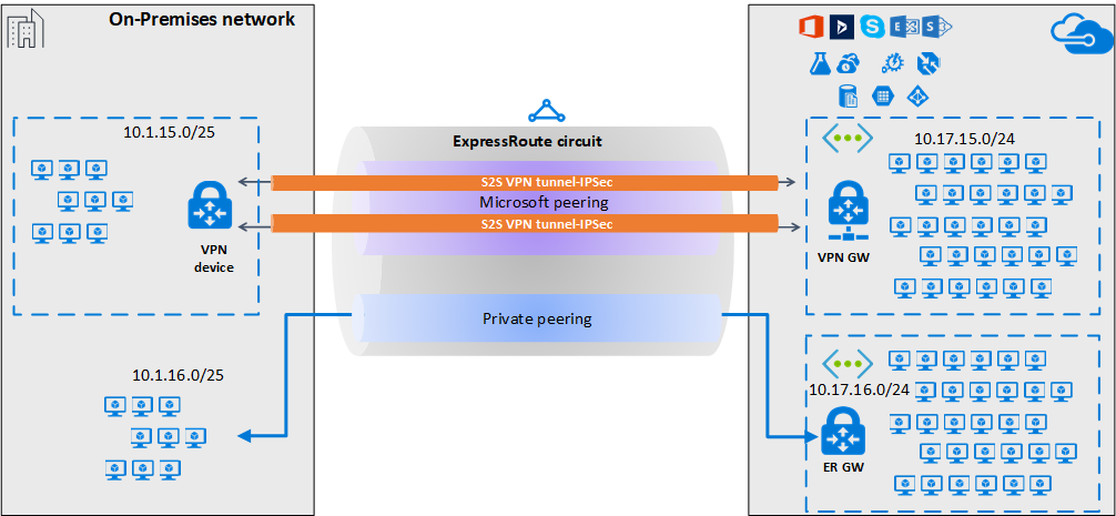
為獲得高可用性和備援功能,您可以透過 ExpressRoute 線路的兩個 MSEE-PE 組設定多個通道,並在通道之間啟用負載平衡。
透過 Microsoft 對等互連的 VPN 通道可以使用 VPN 閘道,或使用透過 Azure Marketplace 取得的適當網路虛擬設備 (NVA) 終止。 您可以使用靜態或動態方式,透過加密通道交換路由,而不會暴露與底層 Microsoft 對等互連交換的路由。 在本文的範例中,BGP (不同於建立 Microsoft 對等互連所使用的 BGP 工作階段) 用於以動態方式,透過加密通道交換前置詞。
重要
針對內部部署端,Microsoft 對等互連通常是在 DMZ 上終止的,而私人對等互連則是在核心網路區域上終止的。 這兩個區域將會使用防火牆加以隔離。 如果您要專門針對透過 ExpressRoute 啟用安全通道來設定 Microsoft 對等互連,請記得僅篩選感興趣且透過 Microsoft 對等互連通告的公用 IP。
工作流程
- 設定 ExpressRoute 線路的 Microsoft 的對等互連。
- 透過 Microsoft 對等互連,向內部部署網路通告選取的 Azure 區域公用前置詞。
- 設定 VPN 閘道並建立 IPsec 通道
- 設定內部部署 VPN 裝置。
- 建立站對站 IPsec/IKE 連線。
- (選擇性) 在內部部署 VPN 裝置上設定防火牆/篩選。
- 測試並驗證 ExpressRoute 線路上的 IPsec 通訊。
1.設定 Microsoft 對等互連
若要設定 ExpressRoute 上的站對站 VPN 連線,您必須使用 ExpressRoute Microsoft 對等互連。
若要設定新的 ExpressRoute 線路,請從 ExpressRoute 先決條件一文開始,然後閱讀建立和修改 ExpressRoute 線路一文。
如果您已經擁有 ExpressRoute 線路,但尚未設定 Microsoft 對等互連,請利用建立和修改 ExpressRoute 線路的對等互連一文,設定 Microsoft 對等互連。
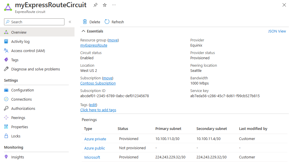
設定線路和 Microsoft 對等互連之後,即可使用 Azure 入口網站 中的 [概觀] 頁面輕鬆檢視它。
2.設定路由篩選
路由篩選可讓您識別想要透過 ExpressRoute 線路的 Microsoft 對等互連使用的服務。 這基本上是所有 BGP 社群值的允許清單。
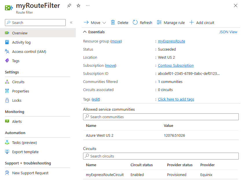
在此範例中,部署僅在 Azure 美國西部 2 區域中。 系統會新增路由篩選規則,以便僅允許 Azure 美國西部 2 區域前置詞的通告,其 BGP 社群值為 12076:51026。 您可以選取 [管理規則] 來指定您想要允許的區域前置詞。
在路由篩選內,您也需要選擇路由篩選要套用的 ExpressRoute 線路。 您可以選取 [新增線路] 來選擇 ExpressRoute 線路。 在上圖中,路由篩選與範例 ExpressRoute 線路相關聯。
2.1 設定路由篩選
設定路由篩選。 如需步驟,請參閱針對 Microsoft 對等互連設定路由篩選。
2.2 驗證 BGP 路由
當您成功透過 ExpressRoute 線路建立 Microsoft 對等互連,並將路由篩選與線路建立關聯之後,您就可以在與 MSE 對等互連的 PE 裝置上驗證從 Microsoft Enterprise Edge (MSE) 收到的 BGP 路由。 驗證命令會根據 PE 裝置的作業系統而有所不同。
Cisco 範例
此範例會使用 Cisco IOS XE 命令。 在範例中,虛擬路由和轉送 (VRF) 執行個體用於隔離對等互連流量。
show ip bgp vpnv4 vrf 10 summary
下列部分輸出顯示從鄰近 *.243.229.34 接收 68 個前置詞,且自發系統號碼 (ASN) 12076 (MSEE):
...

Neighbor        V           AS MsgRcvd MsgSent   TblVer  InQ OutQ Up/Down  State/PfxRcd
X.243.229.34    4        12076   17671   17650    25228    0    0 1w4d           68
若要查看接收自芳鄰的前置詞清單,請使用下列範例:
sh ip bgp vpnv4 vrf 10 neighbors X.243.229.34 received-routes
若要確認您收到一組正確的前置詞,您可進行交叉驗證。 下列 Azure PowerShell 命令輸出會針對每個服務和每個 Azure 區域,列出透過 Microsoft 對等互連通告的前置詞:
Get-AzBgpServiceCommunity
3.設定 VPN 閘道和 IPsec 通道
在本節中,Azure VPN 閘道與內部部署 VPN 裝置之間會建立 IPsec VPN 通道。 這些範例會使用 Cisco Cloud Service Router (CSR1000) VPN 裝置。
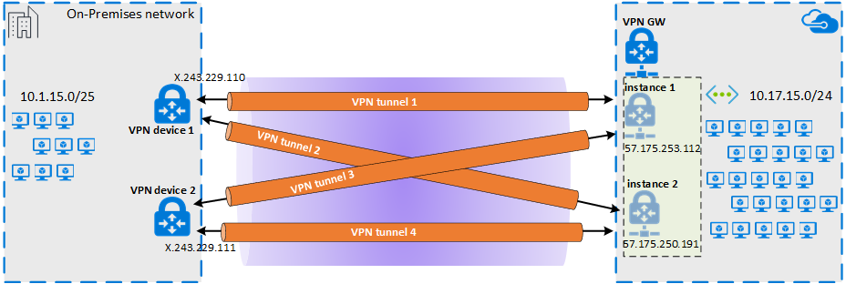
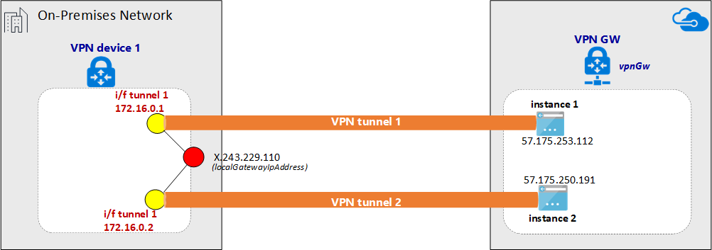
下圖顯示在內部部署 VPN 裝置 1 與 Azure VPN 閘道執行個體組之間建立的 IPsec VPN 通道。 在內部部署 VPN 裝置 2 和 Azure VPN 閘道執行個體組之間建立的兩個 IPsec VPN 通道未在圖表中說明。 未列出設定詳細資料。 不過,擁有更多 VPN 通道可改善高可用性。
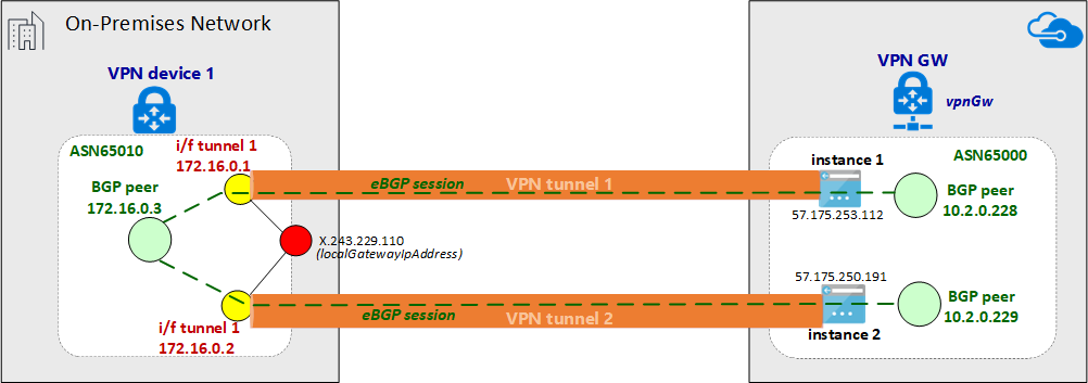
系統會透過 IPsec 通道組建立 eBGP 工作階段,以交換私人網路路由。 下圖顯示透過 IPsec 通道組建立的 eBGP 工作階段:
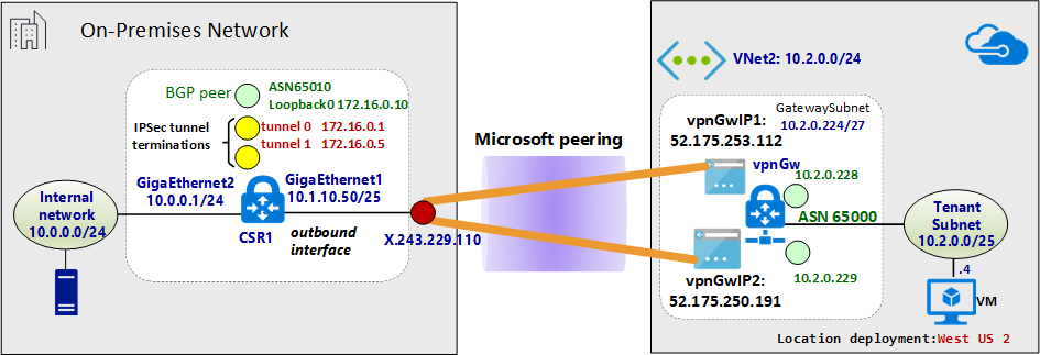
下圖顯示範例網路的抽象概觀:
關於 Azure Resource Manager 範本範例
在這些範例中,VPN 閘道和 IPsec 通道終止是使用 Azure Resource Manager 範本設定的。 如果您不熟悉如何使用 Resource Manager 範本,或是想要了解 Resource Manager 範本的基本概念,請參閱了解 Azure Resource Manager 範本的結構和語法。 本節中的範本會建立綠色字段 Azure 環境 (虛擬網路)。 不過,如果您有現有的虛擬網路,您可以在範本中參考它。 如果您不熟悉 VPN 閘道 IPsec/IKE 站對站設定,請參閱建立站對站連線。
注意
您不需要使用 Azure Resource Manager 範本,就可以建立此設定。 您可以使用 Azure 入口網站或 PowerShell 建立此設定。
3.1 宣告變數
在此範例中,變數宣告對應至範例網路。 宣告變數時,請修改此區段以反映您的環境。
- 變數 localAddressPrefix 是內部部署 IP 位址的陣列,可終止 IPsec 通道。
- gatewaySku 可決定 VPN 輸送量。 如需有關 gatewaySku 和 vpnType 的詳細資訊,請參閱 VPN 閘道組態設定。 如需定價,請參閱 VPN 閘道定價。
- 將 vpnType 設定為 RouteBased。
"variables": {
  "virtualNetworkName": "SecureVNet",       // Name of the Azure VNet
  "azureVNetAddressPrefix": "10.2.0.0/24",  // Address space assigned to the VNet
  "subnetName": "Tenant",                   // subnet name in which tenants exists
  "subnetPrefix": "10.2.0.0/25",            // address space of the tenant subnet
  "gatewaySubnetPrefix": "10.2.0.224/27",   // address space of the gateway subnet
  "localGatewayName": "localGW1",           // name of remote gateway (on-premises)
  "localGatewayIpAddress": "X.243.229.110", // public IP address of the on-premises VPN device
  "localAddressPrefix": [
    "172.16.0.1/32",                        // termination of IPsec tunnel-1 on-premises
    "172.16.0.2/32"                         // termination of IPsec tunnel-2 on-premises
  ],
  "gatewayPublicIPName1": "vpnGwVIP1",    // Public address name of the first VPN gateway instance
  "gatewayPublicIPName2": "vpnGwVIP2",    // Public address name of the second VPN gateway instance
  "gatewayName": "vpnGw",                 // Name of the Azure VPN gateway
  "gatewaySku": "VpnGw1",                 // Azure VPN gateway SKU
  "vpnType": "RouteBased",                // type of VPN gateway
  "sharedKey": "string",                  // shared secret needs to match with on-premises configuration
  "asnVpnGateway": 65000,                 // BGP Autonomous System number assigned to the VPN Gateway
  "asnRemote": 65010,                     // BGP Autonmous Syste number assigned to the on-premises device
  "bgpPeeringAddress": "172.16.0.3",      // IP address of the remote BGP peer on-premises
  "connectionName": "vpn2local1",
  "vnetID": "[resourceId('Microsoft.Network/virtualNetworks', variables('virtualNetworkName'))]",
  "gatewaySubnetRef": "[concat(variables('vnetID'),'/subnets/','GatewaySubnet')]",
  "subnetRef": "[concat(variables('vnetID'),'/subnets/',variables('subnetName'))]",
  "api-version": "2017-06-01"
},
3.2 建立虛擬網路 (虛擬網路)
如果您要將現有的虛擬網路與 VPN 通道產生關聯,您可以略過此步驟。
{
  "apiVersion": "[variables('api-version')]",
  "type": "Microsoft.Network/virtualNetworks",
  "name": "[variables('virtualNetworkName')]",
  "location": "[resourceGroup().location]",
  "properties": {
    "addressSpace": {
      "addressPrefixes": [
        "[variables('azureVNetAddressPrefix')]"
      ]
    },
    "subnets": [
      {
        "name": "[variables('subnetName')]",
        "properties": {
          "addressPrefix": "[variables('subnetPrefix')]"
        }
      },
      {
        "name": "GatewaySubnet",
        "properties": {
          "addressPrefix": "[variables('gatewaySubnetPrefix')]"
        }
      }
    ]
  },
  "comments": "Create a Virtual Network with Subnet1 and Gatewaysubnet"
},
3.3 將公用 IP 位址指派給 VPN 閘道執行個體
為 VPN 閘道的每個執行個體指派一個公用 IP 位址。
{
  "apiVersion": "[variables('api-version')]",
  "type": "Microsoft.Network/publicIPAddresses",
    "name": "[variables('gatewayPublicIPName1')]",
    "location": "[resourceGroup().location]",
    "properties": {
      "publicIPAllocationMethod": "Dynamic"
    },
    "comments": "Public IP for the first instance of the VPN gateway"
  },
  {
    "apiVersion": "[variables('api-version')]",
    "type": "Microsoft.Network/publicIPAddresses",
    "name": "[variables('gatewayPublicIPName2')]",
    "location": "[resourceGroup().location]",
    "properties": {
      "publicIPAllocationMethod": "Dynamic"
    },
    "comments": "Public IP for the second instance of the VPN gateway"
  },
3.4 指定內部部署 VPN 通道終止 (區域網路閘道)
內部部署 VPN 裝置指的是區域網路閘道。 下列 json 程式碼片段也會指定遠端 BGP 對等詳細資料:
{
  "apiVersion": "[variables('api-version')]",
  "type": "Microsoft.Network/localNetworkGateways",
  "name": "[variables('localGatewayName')]",
  "location": "[resourceGroup().location]",
  "properties": {
    "localNetworkAddressSpace": {
      "addressPrefixes": "[variables('localAddressPrefix')]"
    },
    "gatewayIpAddress": "[variables('localGatewayIpAddress')]",
    "bgpSettings": {
      "asn": "[variables('asnRemote')]",
      "bgpPeeringAddress": "[variables('bgpPeeringAddress')]",
      "peerWeight": 0
    }
  },
  "comments": "Local Network Gateway (referred to your on-premises location) with IP address of remote tunnel peering and IP address of remote BGP peer"
},
3.5 建立 VPN 閘道
本節的範本使用主動-主動組態所需要的設定來設定 VPN 閘道。 請記住下列需求:
- 使用 "RouteBased" VpnType 建立 VPN 閘道。 如果您想要在 VPN 閘道與 VPN 內部部署之間啟用 BGP 路由,則此設定是強制性的。
- 若要以主動-主動模式在兩個 VPN 閘道執行個體與指定的內部部署裝置之間建立 VPN 通道,"activeActive" 參數在 Resource Manager 範本中必須設為 true。 若要深入了解高可用性的 VPN 閘道,請參閱高可用性的 VPN 閘道連線。
- 若要在 VPN 通道之間設定 eBGP 工作階段,您必須在任一端指定兩個不同的 ASN。 最好是指定私人 ASN 編號。 如需詳細資訊,請參閱 BGP 和 Azure VPN 閘道的概觀。
{
"apiVersion": "[variables('api-version')]",
"type": "Microsoft.Network/virtualNetworkGateways",
"name": "[variables('gatewayName')]",
"location": "[resourceGroup().location]",
"dependsOn": [
  "[concat('Microsoft.Network/publicIPAddresses/', variables('gatewayPublicIPName1'))]",
  "[concat('Microsoft.Network/publicIPAddresses/', variables('gatewayPublicIPName2'))]",
  "[concat('Microsoft.Network/virtualNetworks/', variables('virtualNetworkName'))]"
],
"properties": {
  "ipConfigurations": [
    {
      "properties": {
        "privateIPAllocationMethod": "Dynamic",
        "subnet": {
          "id": "[variables('gatewaySubnetRef')]"
        },
        "publicIPAddress": {
          "id": "[resourceId('Microsoft.Network/publicIPAddresses',variables('gatewayPublicIPName1'))]"
        }
      },
      "name": "vnetGtwConfig1"
    },
    {
      "properties": {
        "privateIPAllocationMethod": "Dynamic",
        "subnet": {
          "id": "[variables('gatewaySubnetRef')]"
        },
        "publicIPAddress": {
          "id": "[resourceId('Microsoft.Network/publicIPAddresses',variables('gatewayPublicIPName2'))]"
        }
      },
          "name": "vnetGtwConfig2"
        }
      ],
      "sku": {
        "name": "[variables('gatewaySku')]",
        "tier": "[variables('gatewaySku')]"
      },
      "gatewayType": "Vpn",
      "vpnType": "[variables('vpnType')]",
      "enableBgp": true,
      "activeActive": true,
      "bgpSettings": {
        "asn": "[variables('asnVpnGateway')]"
      }
    },
    "comments": "VPN Gateway in active-active configuration with BGP support"
  },
3.6 建立 IPsec 通道
指令碼的最後一個動作會在 Azure VPN 閘道與內部部署 VPN 裝置之間建立 IPsec 通道。
{
  "apiVersion": "[variables('api-version')]",
  "name": "[variables('connectionName')]",
  "type": "Microsoft.Network/connections",
  "location": "[resourceGroup().location]",
  "dependsOn": [
    "[concat('Microsoft.Network/virtualNetworkGateways/', variables('gatewayName'))]",
    "[concat('Microsoft.Network/localNetworkGateways/', variables('localGatewayName'))]"
  ],
  "properties": {
    "virtualNetworkGateway1": {
      "id": "[resourceId('Microsoft.Network/virtualNetworkGateways', variables('gatewayName'))]"
    },
    "localNetworkGateway2": {
      "id": "[resourceId('Microsoft.Network/localNetworkGateways', variables('localGatewayName'))]"
    },
    "connectionType": "IPsec",
    "routingWeight": 0,
    "sharedKey": "[variables('sharedKey')]",
    "enableBGP": "true"
  },
  "comments": "Create a Connection type site-to-site (IPsec) between the Azure VPN Gateway and the VPN device on-premises"
  }
4.設定內部部署 VPN 裝置
Azure VPN 閘道與許多不同廠商的 VPN 裝置相容。 如需已驗證以使用 VPN 閘道的組態資訊和裝置,請參閱 關於 VPN 裝置。
設定 VPN 裝置時,您需要下列項目:
- 共用金鑰。 這個值與您建立站對站 VPN 連線時指定的共用金鑰相同。 這些範例會使用基本的共用金鑰。 我們建議您產生更複雜的金鑰以供使用。
- 您 VPN 閘道的公用 IP 位址。 您可以使用 Azure 入口網站、PowerShell 或 CLI 來檢視公用 IP 位址。 若要使用 Azure 入口網站尋找 VPN 閘道的公用 IP 位址,請瀏覽至 [虛擬網路閘道],然後選取閘道名稱。
eBGP 對等通常是直接連線的 (通常透過 WAN 連線)。 不過,當您要透過 ExpressRoute Microsoft 對等互連,在 IPsec VPN 通道上設定 eBGP 時,在 eBGP 對等之間有多個路由網域。 使用 ebgp-multihop 命令,在兩個非直接連線的對等之間,建立 eBGP 芳鄰關聯性。 在 ebgp-multihop 命令後面的整數會指定 BGP 封包中的存留時間 (TTL) 值。 maximum-paths eibgp 2 命令會針對兩個 BGP 路徑之間的流量,啟用負載平衡。
Cisco CSR1000 範例
下列範例會在當作內部部署 VPN 裝置的 Hyper-V 虛擬機器中,顯示 Cisco CSR1000 的設定:
!
crypto ikev2 proposal az-PROPOSAL
 encryption aes-cbc-256 aes-cbc-128 3des
 integrity sha1
 group 2
!
crypto ikev2 policy az-POLICY
 proposal az-PROPOSAL
!
crypto ikev2 keyring key-peer1
 peer azvpn1
  address 52.175.253.112
  pre-shared-key secret*1234
 !
!
crypto ikev2 keyring key-peer2
 peer azvpn2
  address 52.175.250.191
  pre-shared-key secret*1234
 !
!
!
crypto ikev2 profile az-PROFILE1
 match address local interface GigabitEthernet1
 match identity remote address 52.175.253.112 255.255.255.255
 authentication remote pre-share
 authentication local pre-share
 keyring local key-peer1
!
crypto ikev2 profile az-PROFILE2
 match address local interface GigabitEthernet1
 match identity remote address 52.175.250.191 255.255.255.255
 authentication remote pre-share
 authentication local pre-share
 keyring local key-peer2
!
crypto ikev2 dpd 10 2 on-demand
!
!
crypto ipsec transform-set az-IPSEC-PROPOSAL-SET esp-aes 256 esp-sha-hmac
 mode tunnel
!
crypto ipsec profile az-VTI1
 set transform-set az-IPSEC-PROPOSAL-SET
 set ikev2-profile az-PROFILE1
!
crypto ipsec profile az-VTI2
 set transform-set az-IPSEC-PROPOSAL-SET
 set ikev2-profile az-PROFILE2
!
!
interface Loopback0
 ip address 172.16.0.3 255.255.255.255
!
interface Tunnel0
 ip address 172.16.0.1 255.255.255.255
 ip tcp adjust-mss 1350
 tunnel source GigabitEthernet1
 tunnel mode ipsec ipv4
 tunnel destination 52.175.253.112
 tunnel protection ipsec profile az-VTI1
!
interface Tunnel1
 ip address 172.16.0.2 255.255.255.255
 ip tcp adjust-mss 1350
 tunnel source GigabitEthernet1
 tunnel mode ipsec ipv4
 tunnel destination 52.175.250.191
 tunnel protection ipsec profile az-VTI2
!
interface GigabitEthernet1
 description External interface
 ip address x.243.229.110 255.255.255.252
 negotiation auto
 no mop enabled
 no mop sysid
!
interface GigabitEthernet2
 ip address 10.0.0.1 255.255.255.0
 negotiation auto
 no mop enabled
 no mop sysid
!
router bgp 65010
 bgp router-id interface Loopback0
 bgp log-neighbor-changes
 network 10.0.0.0 mask 255.255.255.0
 network 10.1.10.0 mask 255.255.255.128
 neighbor 10.2.0.228 remote-as 65000
 neighbor 10.2.0.228 ebgp-multihop 5
 neighbor 10.2.0.228 update-source Loopback0
 neighbor 10.2.0.228 soft-reconfiguration inbound
 neighbor 10.2.0.228 filter-list 10 out
 neighbor 10.2.0.229 remote-as 65000
 neighbor 10.2.0.229 ebgp-multihop 5
 neighbor 10.2.0.229 update-source Loopback0
 neighbor 10.2.0.229 soft-reconfiguration inbound
 maximum-paths eibgp 2
!
ip route 0.0.0.0 0.0.0.0 10.1.10.1
ip route 10.2.0.228 255.255.255.255 Tunnel0
ip route 10.2.0.229 255.255.255.255 Tunnel1
!
5.設定 VPN 裝置篩選和防火牆 (選擇性)
根據您的需求,設定防火牆和篩選。
6.測試並驗證 IPsec 通道
IPsec 通道的狀態可以在 Azure VPN 閘道上,透過 PowerShell 命令進行驗證:
Get-AzVirtualNetworkGatewayConnection -Name vpn2local1 -ResourceGroupName myRG | Select-Object ConnectionStatus,EgressBytesTransferred,IngressBytesTransferred | fl
範例輸出︰
ConnectionStatus        : Connected
EgressBytesTransferred  : 17734660
IngressBytesTransferred : 10538211
若要獨立檢查 Azure VPN 閘道執行個體上通道的狀態,請使用下列範例:
Get-AzVirtualNetworkGatewayConnection -Name vpn2local1 -ResourceGroupName myRG | Select-Object -ExpandProperty TunnelConnectionStatus
範例輸出︰
Tunnel                           : vpn2local1_52.175.250.191
ConnectionStatus                 : Connected
IngressBytesTransferred          : 4877438
EgressBytesTransferred           : 8754071
LastConnectionEstablishedUtcTime : 11/04/2017 17:03:30

Tunnel                           : vpn2local1_52.175.253.112
ConnectionStatus                 : Connected
IngressBytesTransferred          : 5660773
EgressBytesTransferred           : 8980589
LastConnectionEstablishedUtcTime : 11/04/2017 17:03:13
您也可以在內部部署 VPN 裝置上檢查通道狀態。
Cisco CSR1000 範例:
show crypto session detail
show crypto ikev2 sa
show crypto ikev2 session detail
show crypto ipsec sa
範例輸出:
csr1#show crypto session detail

Crypto session current status

Code: C - IKE Configuration mode, D - Dead Peer Detection
K - Keepalives, N - NAT-traversal, T - cTCP encapsulation
X - IKE Extended Authentication, F - IKE Fragmentation
R - IKE Auto Reconnect

Interface: Tunnel1
Profile: az-PROFILE2
Uptime: 00:52:46
Session status: UP-ACTIVE
Peer: 52.175.250.191 port 4500 fvrf: (none) ivrf: (none)
      Phase1_id: 52.175.250.191
      Desc: (none)
  Session ID: 3
  IKEv2 SA: local 10.1.10.50/4500 remote 52.175.250.191/4500 Active
          Capabilities:DN connid:3 lifetime:23:07:14
  IPSEC FLOW: permit ip 0.0.0.0/0.0.0.0 0.0.0.0/0.0.0.0
        Active SAs: 2, origin: crypto map
        Inbound:  #pkts dec'ed 279 drop 0 life (KB/Sec) 4607976/433
        Outbound: #pkts enc'ed 164 drop 0 life (KB/Sec) 4607992/433

Interface: Tunnel0
Profile: az-PROFILE1
Uptime: 00:52:43
Session status: UP-ACTIVE
Peer: 52.175.253.112 port 4500 fvrf: (none) ivrf: (none)
      Phase1_id: 52.175.253.112
      Desc: (none)
  Session ID: 2
  IKEv2 SA: local 10.1.10.50/4500 remote 52.175.253.112/4500 Active
          Capabilities:DN connid:2 lifetime:23:07:17
  IPSEC FLOW: permit ip 0.0.0.0/0.0.0.0 0.0.0.0/0.0.0.0
        Active SAs: 2, origin: crypto map
        Inbound:  #pkts dec'ed 668 drop 0 life (KB/Sec) 4607926/437
        Outbound: #pkts enc'ed 477 drop 0 life (KB/Sec) 4607953/437
虛擬通道介面 (VTI) 上的線路通訊協定在 IKE 階段 2 完成之前不會變更為「向上」。 下列命令會驗證安全性關聯:
csr1#show crypto ikev2 sa

IPv4 Crypto IKEv2  SA

Tunnel-id Local                 Remote                fvrf/ivrf            Status
2         10.1.10.50/4500       52.175.253.112/4500   none/none            READY
      Encr: AES-CBC, keysize: 256, PRF: SHA1, Hash: SHA96, DH Grp:2, Auth sign: PSK, Auth verify: PSK
      Life/Active Time: 86400/3277 sec

Tunnel-id Local                 Remote                fvrf/ivrf            Status
3         10.1.10.50/4500       52.175.250.191/4500   none/none            READY
      Encr: AES-CBC, keysize: 256, PRF: SHA1, Hash: SHA96, DH Grp:2, Auth sign: PSK, Auth verify: PSK
      Life/Active Time: 86400/3280 sec

IPv6 Crypto IKEv2  SA

csr1#show crypto ipsec sa | inc encaps|decaps
    #pkts encaps: 177, #pkts encrypt: 177, #pkts digest: 177
    #pkts decaps: 296, #pkts decrypt: 296, #pkts verify: 296
    #pkts encaps: 554, #pkts encrypt: 554, #pkts digest: 554
    #pkts decaps: 746, #pkts decrypt: 746, #pkts verify: 746
確認內部網路內部部署與 Azure 虛擬網路之間的端對端連線
如果 IPsec 通道已啟動且靜態路由設定正確,則您應該能夠 Ping 遠端 BGP 對等的 IP 位址:
csr1#ping 10.2.0.228
Type escape sequence to abort.
Sending 5, 100-byte ICMP Echos to 10.2.0.228, timeout is 2 seconds:
!!!!!
Success rate is 100 percent (5/5), round-trip min/avg/max = 5/5/5 ms

#ping 10.2.0.229
Type escape sequence to abort.
Sending 5, 100-byte ICMP Echos to 10.2.0.229, timeout is 2 seconds:
!!!!!
Success rate is 100 percent (5/5), round-trip min/avg/max = 4/5/6 ms
透過 IPsec 驗證 BGP 工作階段
在 Azure VPN 閘道上,驗證 BGP 對等的狀態:
Get-AzVirtualNetworkGatewayBGPPeerStatus -VirtualNetworkGatewayName vpnGtw -ResourceGroupName SEA-C1-VPN-ER | ft
範例輸出︰
  Asn ConnectedDuration LocalAddress MessagesReceived MessagesSent Neighbor    RoutesReceived State
  --- ----------------- ------------ ---------------- ------------ --------    -------------- -----
65010 00:57:19.9003584  10.2.0.228               68           72   172.16.0.10              2 Connected
65000                   10.2.0.228                0            0   10.2.0.228               0 Unknown
65000 07:13:51.0109601  10.2.0.228              507          500   10.2.0.229               6 Connected
若要驗證透過 VPN 集訊器內部部署的 eBGP 收到的網路首碼清單,您可以依屬性"Origin" 進行篩選:
Get-AzVirtualNetworkGatewayLearnedRoute -VirtualNetworkGatewayName vpnGtw -ResourceGroupName myRG | Where-Object Origin -eq "EBgp" |ft
在範例輸出中,ASN 65010 是 VPN 內部部署中的 BGP 自發系統編號。
AsPath LocalAddress Network      NextHop     Origin SourcePeer  Weight
------ ------------ -------      -------     ------ ----------  ------
65010  10.2.0.228   10.1.10.0/25 172.16.0.10 EBgp   172.16.0.10  32768
65010  10.2.0.228   10.0.0.0/24  172.16.0.10 EBgp   172.16.0.10  32768
查看通告的路由清單:
Get-AzVirtualNetworkGatewayAdvertisedRoute -VirtualNetworkGatewayName vpnGtw -ResourceGroupName myRG -Peer 10.2.0.228 | ft
範例輸出︰
AsPath LocalAddress Network        NextHop    Origin SourcePeer Weight
------ ------------ -------        -------    ------ ---------- ------
       10.2.0.229   10.2.0.0/24    10.2.0.229 Igp                  0
       10.2.0.229   172.16.0.10/32 10.2.0.229 Igp                  0
       10.2.0.229   172.16.0.5/32  10.2.0.229 Igp                  0
       10.2.0.229   172.16.0.1/32  10.2.0.229 Igp                  0
65010  10.2.0.229   10.1.10.0/25   10.2.0.229 Igp                  0
65010  10.2.0.229   10.0.0.0/24    10.2.0.229 Igp                  0
內部部署 Cisco CSR1000 的範例:
csr1#show ip bgp neighbors 10.2.0.228 routes
BGP table version is 7, local router ID is 172.16.0.10
Status codes: s suppressed, d damped, h history, * valid, > best, i - internal,
              r RIB-failure, S Stale, m multipath, b backup-path, f RT-Filter,
              x best-external, a additional-path, c RIB-compressed,
              t secondary path,
Origin codes: i - IGP, e - EGP, ? - incomplete
RPKI validation codes: V valid, I invalid, N Not found

     Network          Next Hop            Metric LocPrf Weight Path
 *>   10.2.0.0/24      10.2.0.228                             0 65000 i
 r>   172.16.0.1/32    10.2.0.228                             0 65000 i
 r>   172.16.0.2/32    10.2.0.228                             0 65000 i
 r>   172.16.0.3/32   10.2.0.228                             0 65000 i

Total number of prefixes 4
您可以使用下列命令,列出從內部部署 Cisco CSR1000 向 Azure VPN 閘道通告的網路清單:
csr1#show ip bgp neighbors 10.2.0.228 advertised-routes
BGP table version is 7, local router ID is 172.16.0.10
Status codes: s suppressed, d damped, h history, * valid, > best, i - internal,
              r RIB-failure, S Stale, m multipath, b backup-path, f RT-Filter,
              x best-external, a additional-path, c RIB-compressed,
              t secondary path,
Origin codes: i - IGP, e - EGP, ? - incomplete
RPKI validation codes: V valid, I invalid, N Not found

     Network          Next Hop            Metric LocPrf Weight Path
 *>   10.0.0.0/24      0.0.0.0                  0         32768 i
 *>   10.1.10.0/25     0.0.0.0                  0         32768 i

Total number of prefixes 2
下一步
意見反應
即將登場:在 2024 年,我們將逐步淘汰 GitHub 問題作為內容的意見反應機制,並將它取代為新的意見反應系統。 如需詳細資訊,請參閱:https://aka.ms/ContentUserFeedback。
提交並檢視相關的意見反應