3D 圖形概觀
Windows Presentation Foundation (WPF) 中的 3D 功能可讓開發人員在標記和程式代碼中繪製、轉換和動畫顯示 3D 圖形。 開發人員可以結合 2D 和 3D 圖形來建立豐富的控件、提供複雜的數據圖例,或增強應用程式的介面用戶體驗。 WPF 中的 3D 支援並非設計來提供功能完整的遊戲開發平臺。 本主題提供 WPF 圖形系統中 3D 功能的概觀。
2D 容器中的 3D
WPF 中的 3D 圖形內容會封裝在可以參與二維元素結構的 元素 Viewport3D中。 圖形系統會將 Viewport3D 視為二維視覺專案,就像 WPF 中的許多其他項目一樣。 Viewport3D 可作為視窗,即檢視區,進入立體場景。 更準確地說,這是投影 3D 場景的表面。
在傳統的 2D 應用程式中,如同 Viewport3D 使用 Grid 或 Canvas 等其他容器元素一樣。 雖然您可以在相同的場景圖形中搭配其他 2D 繪圖物件使用 Viewport3D ,但是您無法在 內 Viewport3D交錯 2D 和 3D 物件。 本主題將著重於如何在 內 Viewport3D繪製 3D 圖形。
3D 座標空間
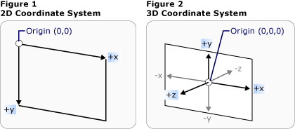
2D 圖形的 WPF 座標系統會找出轉譯區域左上方的原點(通常是螢幕)。 在 2D 系統中,正 x 軸值會往右繼續,而正 y 軸值會往下繼續。 不過,在 3D 座標系統中,原點位於轉譯區域的中央,正 x 軸值會往右繼續,但正 y 軸值會往上移動,而正 z 軸值會往外往外,朝檢視者走去。

傳統的 2D 和 3D 座標系統表示法
這些座標軸所定義的空間是 WPF 中 3D 物件的固定參考框架。 當您在此空間中建置模型,並建立光線和觀景窗來檢視這些模型時,有助於區分此靜態參考座標系 (或稱為「世界空間」) 與您為每個模型套用轉換時建立的當地參考座標系。 也請記住,在世界空間中的物件取決於光線和觀景窗設定,可能看起來完全不同,或者完全無法看見,但觀景窗的位置不會改變世界空間中物件的位置。
觀景窗和投影
在 2D 工作的開發人員習慣於將繪圖基本類型定位在二維螢幕上。 當您建立 3D 場景時,請務必記住,您確定要建立 3D 物件的 2D 表示法。 由於 3D 場景看起來會根據旁觀者的觀點而有所不同,因此您必須指定該檢視點。 類別 Camera 可讓您指定 3D 場景的這個檢視點。
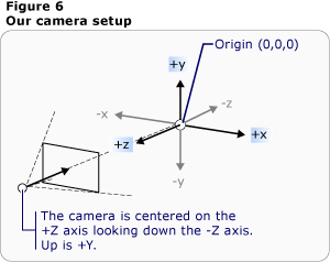
另一個瞭解 3D 場景如何在 2D 表面呈現的方式,就是將場景描述為檢視表面的投影。 ProjectionCamera可讓您指定不同的投影及其屬性,以變更旁觀者看到 3D 模型的方式。 PerspectiveCamera指定預選場景的投影。 換句話說,提供 PerspectiveCamera 消失點的觀點。 您可以指定觀景窗在場景座標空間中的位置、觀景窗的方向和視野,以及定義場景中「向上」方向的向量。 下圖說明 PerspectiveCamera的投影。
限制 NearPlaneDistance 相機投影範圍的 和 FarPlaneDistance 屬性 ProjectionCamera 。 由於觀景窗可能會位在場景中的任何地方,觀景窗有可能實際上就位在模型內部或非常靠近模型,因此更難正確區分物件。 NearPlaneDistance 可讓您指定距離相機的最小距離,因此不會繪製物件。 相反地, FarPlaneDistance 可讓您指定距離相機以外的距離,而該距離不會繪製物件,這可確保無法辨識的物件不會包含在場景中。

觀景窗位置
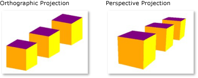
OrthographicCamera 會指定 3D 模型的正交投影到 2D 視覺表面。 與其他觀景窗相同,它會指定位置、檢視方向和「向上」方向。 不過,不同於 PerspectiveCamera, OrthographicCamera 描述不包含前景前景的投影。 換句話說, OrthographicCamera 描述側邊平行的檢視方塊,而不是在相機的某個點相遇的檢視方塊。 下圖顯示與使用 PerspectiveCamera 和 OrthographicCamera檢視相同的模型。

透視投影和正視投影
下列程式碼示範一些典型的觀景窗設定。
// Defines the camera used to view the 3D object. In order to view the 3D object,
// the camera must be positioned and pointed such that the object is within view
// of the camera.
PerspectiveCamera myPCamera = new PerspectiveCamera();

// Specify where in the 3D scene the camera is.
myPCamera.Position = new Point3D(0, 0, 2);

// Specify the direction that the camera is pointing.
myPCamera.LookDirection = new Vector3D(0, 0, -1);

// Define camera's horizontal field of view in degrees.
myPCamera.FieldOfView = 60;

// Asign the camera to the viewport
myViewport3D.Camera = myPCamera;
' Defines the camera used to view the 3D object. In order to view the 3D object,
' the camera must be positioned and pointed such that the object is within view
' of the camera.
Dim myPCamera As New PerspectiveCamera()

' Specify where in the 3D scene the camera is.
myPCamera.Position = New Point3D(0, 0, 2)

' Specify the direction that the camera is pointing.
myPCamera.LookDirection = New Vector3D(0, 0, -1)

' Define camera's horizontal field of view in degrees.
myPCamera.FieldOfView = 60

' Asign the camera to the viewport
myViewport3D.Camera = myPCamera
模型和網格基元
Model3D 是代表泛型 3D 物件的抽象基類。 若要建置 3D 場景,您需要一些物件才能檢視,以及組成場景圖形的物件衍生自 Model3D。 目前,WPF 支援使用 GeometryModel3D模型化幾何。 Geometry此模型的 屬性會採用網格基本類型。
若要建立模型,請先建立基元 (也就是網格)。 3D 基本類型是形成單一 3D 實體的頂點集合。 大部分的 3D 系統都提供以最簡單的封閉圖模型建立的基本類型:由三個頂點定義的三角形。 因為三角形的三個點共面,所以您可以持續加入三角形,以塑造出更複雜的圖形 (稱為網格)。
WPF 3D 系統目前提供 MeshGeometry3D 類別,可讓您指定任何幾何;它目前不支持預先定義的 3D 基本類型,例如球體和立方體形式。 藉由指定三角形頂點清單做為其 Positions 屬性,開始建立 MeshGeometry3D 。 每個頂點都會指定為 Point3D。 (在 XAML 中,將此屬性指定為三個群組的數字清單,代表每個頂點的座標。視其幾何而定,您的網格可能由許多三角形組成,其中有些會共用相同的角落(頂點)。 若要正確繪製網格,WPF 需要哪些頂點的相關信息會由哪些三角形共用。 您可以使用 屬性來指定三角形索引 TriangleIndices 的清單,以提供這項資訊。 此清單會指定清單中指定 Positions 之點決定三角形的順序。
<GeometryModel3D>
  <GeometryModel3D.Geometry>
          <MeshGeometry3D
              Positions="-1 -1 0  1 -1 0  -1 1 0  1 1 0"
              Normals="0 0 1  0 0 1  0 0 1  0 0 1"
              TextureCoordinates="0 1  1 1  0 0  1 0   "
              TriangleIndices="0 1 2  1 3 2" />
      </GeometryModel3D.Geometry>
      <GeometryModel3D.Material>
          <DiffuseMaterial>
              <DiffuseMaterial.Brush>
                  <SolidColorBrush Color="Cyan" Opacity="0.3"/>
              </DiffuseMaterial.Brush>
          </DiffuseMaterial>
      </GeometryModel3D.Material>
  <!-- Translate the plane. -->
      <GeometryModel3D.Transform>
          <TranslateTransform3D
            OffsetX="2" OffsetY="0" OffsetZ="-1"   >
          </TranslateTransform3D>
      </GeometryModel3D.Transform>
  </GeometryModel3D>
在上述範例中 Positions ,清單會指定四個頂點來定義矩形網格。 屬性 TriangleIndices 會指定三個索引的兩組清單。 清單中的每個數位都會參考清單中的位移 Positions 。 例如,清單指定的 Positions 前三個頂點是 (-1,-1,0)、 (1,-1,0)和 (-1,1,0)。 清單指定的 TriangleIndices 前三個索引是 0、1 和 2,對應至清單中的第一個、第二個和第三個點 Positions 。 因此,組成矩形模型的第一個三角形會從 組成 (-1,-1,0) 到 (1,-1,0)(-1,1,0),而第二個三角形會以類似的方式決定。
您可以指定 和 TextureCoordinates 屬性的值Normals,以繼續定義模型。 若要轉譯模型的表面,圖形系統需要表面在任意指定的三角形處面對哪個方向的資訊。 系統會使用此資訊來進行模型的光線計算︰直接面向光源的表面看起來就會比偏離光線一些角度的表面還亮。 雖然 WPF 可以使用位置座標來判斷預設的法向量,但您也可以指定不同的法向量來近似曲線表面的外觀。
屬性 TextureCoordinates 會指定的集合 Point,告知圖形系統如何對應座標,以決定紋理如何繪製到網格頂點。 TextureCoordinates 會指定為介於零和 1 之間的值,包含 。 Normals如同 屬性,圖形系統可以計算預設紋理座標,但您可以選擇設定不同的紋理座標來控制包含重複模式一部分之紋理的對應。 您可以在後續的主題或 Managed Direct3D SDK 中找到有關紋理座標的詳細資訊。
下列範例示範如何以程序性程式碼建立立方體模型的一個面。 您可以將整個立方體繪製成單 GeometryModel3D一;本範例會將立方體的臉部繪製為不同的模型,以便稍後將個別紋理套用至每個臉部。
MeshGeometry3D side1Plane = new MeshGeometry3D();
Private side1Plane As New MeshGeometry3D()
side1Plane.Positions.Add(new Point3D(-0.5, -0.5, -0.5));
side1Plane.Positions.Add(new Point3D(-0.5, 0.5, -0.5));
side1Plane.Positions.Add(new Point3D(0.5, 0.5, -0.5));
side1Plane.Positions.Add(new Point3D(0.5, 0.5, -0.5));
side1Plane.Positions.Add(new Point3D(0.5, -0.5, -0.5));
side1Plane.Positions.Add(new Point3D(-0.5, -0.5, -0.5));

side1Plane.TriangleIndices.Add(0);
side1Plane.TriangleIndices.Add(1);
side1Plane.TriangleIndices.Add(2);
side1Plane.TriangleIndices.Add(3);
side1Plane.TriangleIndices.Add(4);
side1Plane.TriangleIndices.Add(5);

side1Plane.Normals.Add(new Vector3D(0, 0, -1));
side1Plane.Normals.Add(new Vector3D(0, 0, -1));
side1Plane.Normals.Add(new Vector3D(0, 0, -1));
side1Plane.Normals.Add(new Vector3D(0, 0, -1));
side1Plane.Normals.Add(new Vector3D(0, 0, -1));
side1Plane.Normals.Add(new Vector3D(0, 0, -1));

side1Plane.TextureCoordinates.Add(new Point(1, 0));
side1Plane.TextureCoordinates.Add(new Point(1, 1));
side1Plane.TextureCoordinates.Add(new Point(0, 1));
side1Plane.TextureCoordinates.Add(new Point(0, 1));
side1Plane.TextureCoordinates.Add(new Point(0, 0));
side1Plane.TextureCoordinates.Add(new Point(1, 0));
side1Plane.Positions.Add(New Point3D(-0.5, -0.5, -0.5))
side1Plane.Positions.Add(New Point3D(-0.5, 0.5, -0.5))
side1Plane.Positions.Add(New Point3D(0.5, 0.5, -0.5))
side1Plane.Positions.Add(New Point3D(0.5, 0.5, -0.5))
side1Plane.Positions.Add(New Point3D(0.5, -0.5, -0.5))
side1Plane.Positions.Add(New Point3D(-0.5, -0.5, -0.5))

side1Plane.TriangleIndices.Add(0)
side1Plane.TriangleIndices.Add(1)
side1Plane.TriangleIndices.Add(2)
side1Plane.TriangleIndices.Add(3)
side1Plane.TriangleIndices.Add(4)
side1Plane.TriangleIndices.Add(5)

side1Plane.Normals.Add(New Vector3D(0, 0, -1))
side1Plane.Normals.Add(New Vector3D(0, 0, -1))
side1Plane.Normals.Add(New Vector3D(0, 0, -1))
side1Plane.Normals.Add(New Vector3D(0, 0, -1))
side1Plane.Normals.Add(New Vector3D(0, 0, -1))
side1Plane.Normals.Add(New Vector3D(0, 0, -1))

side1Plane.TextureCoordinates.Add(New Point(1, 0))
side1Plane.TextureCoordinates.Add(New Point(1, 1))
side1Plane.TextureCoordinates.Add(New Point(0, 1))
side1Plane.TextureCoordinates.Add(New Point(0, 1))
side1Plane.TextureCoordinates.Add(New Point(0, 0))
side1Plane.TextureCoordinates.Add(New Point(1, 0))
對模型套用材質
若要讓網格看起來像三維物件,就必須套用紋理以涵蓋由其頂點和三角形所定義的表面,讓觀景窗可以點亮並投影表面。 在 2D 中 Brush ,您可以使用 類別,將色彩、圖樣、漸層或其他視覺內容套用至畫面的區域。 不過,3D 對象的外觀是光源模型的函式,而不只是套用至它們的色彩或圖樣。 真實的物體會根據物體表面的質地以不同方式反射光線︰光滑而閃亮的表面看起來會與粗糙或黯淡的表面不同,而一些物體看起來會吸收光線,一些物體則會發亮。 您可以將所有相同的筆刷套用至可以套用至 2D 物件的 3D 物件,但無法直接套用它們。
若要定義模型介面的特性,WPF 會使用 Material 抽象類。 Material 的具體子類別會決定模型表面的一些外觀特性,每個特性也提供您可以傳遞 SolidColorBrush、TileBrush 或 VisualBrush 的 Brush 屬性。
DiffuseMaterial 指定筆刷會套用至模型,就像該模型以擴散方式點亮一樣。 使用擴散材料最類似於直接在 2D 模型上使用筆刷;模型表面不會像閃亮一樣反射光線。
SpecularMaterial 指定筆刷會套用至模型,就像模型的表面是硬式或閃亮的,能夠反映醒目提示。 您可以藉由指定 屬性的值 SpecularPower ,來設定紋理會建議此反射品質或「閃亮」的程度。
EmissiveMaterial 可讓您指定將套用紋理,就像模型發出與筆刷色彩相等的光線一樣。 這不會讓模型變成光源。不過,這會影響陰影處理的方式,與透過 DiffuseMaterial 或 SpecularMaterial 加上紋理的方式不同。
為了獲得更好的效能,從 GeometryModel3D 場景中撲殺的臉部(那些視線不足的臉部,因為它們位於相機模型的另一邊)。 若要指定 Material ,以套用至類似平面的模型背面,請設定模型的 BackMaterial 屬性。
若要達到某些表面質地,例如發光或反射效果,您可以對模型連續套用數種不同的筆刷。 您可以使用 類別來套用和重複使用多個材質 MaterialGroup 。 在多個轉譯階段中,會從頭到尾套用 MaterialGroup 的子系。
下列程式代碼範例示範如何將純色和繪圖當做筆刷套用至 3D 模型。
<GeometryModel3D.Material>
    <DiffuseMaterial>
        <DiffuseMaterial.Brush>
            <SolidColorBrush Color="Cyan" Opacity="0.3"/>
        </DiffuseMaterial.Brush>
    </DiffuseMaterial>
</GeometryModel3D.Material>
<DrawingBrush x:Key="patternBrush" Viewport="0,0,0.1,0.1" TileMode="Tile">
  <DrawingBrush.Drawing>
    <DrawingGroup>
      <DrawingGroup.Children>
        <GeometryDrawing Geometry="M0,0.1 L0.1,0 1,0.9, 0.9,1z"
          Brush="Gray" />
        <GeometryDrawing Geometry="M0.9,0 L1,0.1 0.1,1 0,0.9z"
          Brush="Gray" />
        <GeometryDrawing Geometry="M0.25,0.25 L0.5,0.125 0.75,0.25 0.5,0.5z"
          Brush="#FFFF00" />
        <GeometryDrawing Geometry="M0.25,0.75 L0.5,0.875 0.75,0.75 0.5,0.5z"
          Brush="Black" />
        <GeometryDrawing Geometry="M0.25,0.75 L0.125,0.5 0.25,0.25 0.5,0.5z"
          Brush="#FF0000" />
        <GeometryDrawing Geometry="M0.75,0.25 L0.875,0.5 0.75,0.75 0.5,0.5z"
          Brush="MediumBlue" />
      </DrawingGroup.Children>
    </DrawingGroup>
  </DrawingBrush.Drawing>
</DrawingBrush>
DiffuseMaterial side5Material = new DiffuseMaterial((Brush)Application.Current.Resources["patternBrush"]);
Dim side5Material As New DiffuseMaterial(CType(Application.Current.Resources("patternBrush"), Brush))
場景照明
3D 圖形中的光線會執行光線在真實世界中執行的動作:它們會使表面可見。 而且,光線還會決定投影時要包含場景的哪個部分。 WPF 中的光線物件會建立各種光線和陰影效果,並模型化為各種真實世界燈光的行為。 在您的場景中至少包含一個光線,或不會顯示任何模型。
下列燈光衍生自基類 Light:
AmbientLight:提供環境光源,無論物件的位置或方向為何,都能統一照亮所有物件。
DirectionalLight:像遙遠的光源一樣照亮。 方向燈指定 Direction 為 Vector3D,但沒有指定的位置。
PointLight:像附近的光源一樣照亮。 PointLights 有一個位置,並從該位置投射光線。 場景中的物件會根據其相對於光線的位置和距離來照明。 PointLightBaseRange會公開 屬性,決定模型不會由光線照亮的距離。 PointLight 也會公開衰減屬性,以決定光線強度在距離上的減弱方式。 您可以為光線衰減指定常數、線性插補或二次插補。
SpotLight:繼承自 PointLight。 Spotlight 照明的方式類似 PointLight,而且有位置和方向兩者。 它們會將光線投射在由 和 InnerConeAngleOuterConeAngle 屬性所設定的圓錐形區域中,以度為單位指定。
燈光是 Model3D 物件,因此您可以轉換和建立光線屬性的動畫效果,包括位置、色彩、方向和範圍。
<ModelVisual3D.Content>
    <AmbientLight Color="#333333" />
</ModelVisual3D.Content>
DirectionalLight myDirLight = new DirectionalLight();
Private myDirLight As New DirectionalLight()
myDirLight.Color = Colors.White;
myDirLight.Direction = new Vector3D(-3, -4, -5);
myDirLight.Color = Colors.White
myDirLight.Direction = New Vector3D(-3, -4, -5)
modelGroup.Children.Add(myDirLight);
modelGroup.Children.Add(myDirLight)
轉換模型
當您建立模型時,模型在場景中有特定的位置。 若要在場景中四處移動模型、旋轉模型,或變更模型的大小,變更定義模型的頂點本身並不實用。 相反地,就像在 2D 中一樣,您會將轉換套用至模型。
每個模型物件都有一個 Transform 屬性,您可以移動、重新導向或調整模型的大小。 當您套用轉換時,可以透過轉換所指定的任何向量或值,有效率地位移模型的所有點。 換句話說,您已經轉換定義模型所在的座標空間 (「模型空間」),但尚未變更在整個場景的座標系統 (「世界空間」) 中組成模型幾何的值。
如需轉換模型的詳細資訊,請參閱 3D 轉換概觀。
以動畫顯示模型
WPF 3D 實作會參與與 2D 圖形相同的計時和動畫系統。 換句話說,若要建立 3D 場景的動畫效果,請以動畫顯示其模型的屬性。 您可以直接以動畫顯示基元的屬性,但是以動畫顯示變更模型位置或外觀的轉換通常更容易。 因為轉換可以套用至對象和個別模型,所以可以將一組動畫套用至 Model3DGroup Model3DGroup 的子系,並將另一組動畫套用至一組子物件。 您也可以以動畫顯示場景光線的屬性,達到各種視覺效果。 最後,您還可以選擇以動畫顯示觀景窗的位置或視野,以動畫顯示投影本身。 如需 WPF 計時和動畫系統的背景資訊,請參閱 動畫概觀、 分鏡腳本概觀和 Freezable 物件概觀 主題。
若要在 WPF 中建立對象動畫,請建立時間軸、定義動畫(這確實是一些屬性值隨著時間的變化),並指定要套用動畫的屬性。 由於 3D 場景中的所有物件都是 的 Viewport3D子系,因此您想要套用至場景的任何動畫所設定的屬性都是 Viewport3D 的屬性。
假設您想要讓模型就地搖晃。 您可以選擇將 套用 RotateTransform3D 至模型,並以動畫顯示其旋轉軸從一個向量到另一個向量。 下列程式碼範例示範如何對轉換之 Rotation3D 的 Axis 屬性套用 Vector3DAnimation,假設 RotateTransform3D 是要使用 TransformGroup 對模型套用的其中一個轉換。
//Define a rotation
RotateTransform3D myRotateTransform = new RotateTransform3D(new AxisAngleRotation3D(new Vector3D(0, 1, 0), 1));
'Define a rotation
Dim myRotateTransform As New RotateTransform3D(New AxisAngleRotation3D(New Vector3D(0, 1, 0), 1))
Vector3DAnimation myVectorAnimation = new Vector3DAnimation(new Vector3D(-1, -1, -1), new Duration(TimeSpan.FromMilliseconds(5000)));
myVectorAnimation.RepeatBehavior = RepeatBehavior.Forever;
Dim myVectorAnimation As New Vector3DAnimation(New Vector3D(-1, -1, -1), New Duration(TimeSpan.FromMilliseconds(5000)))
myVectorAnimation.RepeatBehavior = RepeatBehavior.Forever
myRotateTransform.Rotation.BeginAnimation(AxisAngleRotation3D.AxisProperty, myVectorAnimation);
myRotateTransform.Rotation.BeginAnimation(AxisAngleRotation3D.AxisProperty, myVectorAnimation)
//Add transformation to the model
cube1TransformGroup.Children.Add(myRotateTransform);
'Add transformation to the model
cube1TransformGroup.Children.Add(myRotateTransform)
將 3D 內容新增至視窗
若要轉譯場景,請將模型和燈光新增至 Model3DGroup,然後將 設定 Model3DGroup 為 Content 的 ModelVisual3D。 ModelVisual3D將加入至 Children 的Viewport3D集合。 藉由設定相機Camera的 屬性,將相機新增至 Viewport3D 。
最後,將 新增 Viewport3D 至視窗。 Viewport3D當 包含 為 Canvas 等版面配置項目的內容時,請藉由設定檢視區3D 的大小Height和Width屬性(繼承自 FrameworkElement) 來指定 Viewport3D 的大小。
<UserControl x:Class="HostingWpfUserControlInWf.UserControl1"
    xmlns="http://schemas.microsoft.com/winfx/2006/xaml/presentation"
    xmlns:x="http://schemas.microsoft.com/winfx/2006/xaml"
    >

    <Grid>

      <!-- Place a Label control at the top of the view. -->
      <Label
                HorizontalAlignment="Center"
                TextBlock.TextAlignment="Center"
                FontSize="20"
                Foreground="Red"
                Content="Model: Cone"/>

      <!-- Viewport3D is the rendering surface. -->
      <Viewport3D Name="myViewport" >

        <!-- Add a camera. -->
        <Viewport3D.Camera>
          <PerspectiveCamera
                        FarPlaneDistance="20"
                        LookDirection="0,0,1"
                        UpDirection="0,1,0"
                        NearPlaneDistance="1"
                        Position="0,0,-3"
                        FieldOfView="45" />
        </Viewport3D.Camera>

        <!-- Add models. -->
        <Viewport3D.Children>

          <ModelVisual3D>
            <ModelVisual3D.Content>

              <Model3DGroup >
                <Model3DGroup.Children>

                  <!-- Lights, MeshGeometry3D and DiffuseMaterial objects are added to the ModelVisual3D. -->
                  <DirectionalLight Color="#FFFFFFFF" Direction="3,-4,5" />

                  <!-- Define a red cone. -->
                  <GeometryModel3D>

                    <GeometryModel3D.Geometry>
                      <MeshGeometry3D
    Positions="0.293893 -0.5 0.404509  0.475528 -0.5 0.154509  0 0.5 0  0.475528 -0.5 0.154509  0 0.5 0  0 0.5 0  0.475528 -0.5 0.154509  0.475528 -0.5 -0.154509  0 0.5 0  0.475528 -0.5 -0.154509  0 0.5 0  0 0.5 0  0.475528 -0.5 -0.154509  0.293893 -0.5 -0.404509  0 0.5 0  0.293893 -0.5 -0.404509  0 0.5 0  0 0.5 0  0.293893 -0.5 -0.404509  0 -0.5 -0.5  0 0.5 0  0 -0.5 -0.5  0 0.5 0  0 0.5 0  0 -0.5 -0.5  -0.293893 -0.5 -0.404509  0 0.5 0  -0.293893 -0.5 -0.404509  0 0.5 0  0 0.5 0  -0.293893 -0.5 -0.404509  -0.475528 -0.5 -0.154509  0 0.5 0  -0.475528 -0.5 -0.154509  0 0.5 0  0 0.5 0  -0.475528 -0.5 -0.154509  -0.475528 -0.5 0.154509  0 0.5 0  -0.475528 -0.5 0.154509  0 0.5 0  0 0.5 0  -0.475528 -0.5 0.154509  -0.293892 -0.5 0.404509  0 0.5 0  -0.293892 -0.5 0.404509  0 0.5 0  0 0.5 0  -0.293892 -0.5 0.404509  0 -0.5 0.5  0 0.5 0  0 -0.5 0.5  0 0.5 0  0 0.5 0  0 -0.5 0.5  0.293893 -0.5 0.404509  0 0.5 0  0.293893 -0.5 0.404509  0 0.5 0  0 0.5 0  "
    Normals="0.7236065,0.4472139,0.5257313  0.2763934,0.4472138,0.8506507  0.5308242,0.4294462,0.7306172  0.2763934,0.4472138,0.8506507  0,0.4294458,0.9030925  0.5308242,0.4294462,0.7306172  0.2763934,0.4472138,0.8506507  -0.2763934,0.4472138,0.8506507  0,0.4294458,0.9030925  -0.2763934,0.4472138,0.8506507  -0.5308242,0.4294462,0.7306172  0,0.4294458,0.9030925  -0.2763934,0.4472138,0.8506507  -0.7236065,0.4472139,0.5257313  -0.5308242,0.4294462,0.7306172  -0.7236065,0.4472139,0.5257313  -0.858892,0.429446,0.279071  -0.5308242,0.4294462,0.7306172  -0.7236065,0.4472139,0.5257313  -0.8944269,0.4472139,0  -0.858892,0.429446,0.279071  -0.8944269,0.4472139,0  -0.858892,0.429446,-0.279071  -0.858892,0.429446,0.279071  -0.8944269,0.4472139,0  -0.7236065,0.4472139,-0.5257313  -0.858892,0.429446,-0.279071  -0.7236065,0.4472139,-0.5257313  -0.5308242,0.4294462,-0.7306172  -0.858892,0.429446,-0.279071  -0.7236065,0.4472139,-0.5257313  -0.2763934,0.4472138,-0.8506507  -0.5308242,0.4294462,-0.7306172  -0.2763934,0.4472138,-0.8506507  0,0.4294458,-0.9030925  -0.5308242,0.4294462,-0.7306172  -0.2763934,0.4472138,-0.8506507  0.2763934,0.4472138,-0.8506507  0,0.4294458,-0.9030925  0.2763934,0.4472138,-0.8506507  0.5308249,0.4294459,-0.7306169  0,0.4294458,-0.9030925  0.2763934,0.4472138,-0.8506507  0.7236068,0.4472141,-0.5257306  0.5308249,0.4294459,-0.7306169  0.7236068,0.4472141,-0.5257306  0.8588922,0.4294461,-0.27907  0.5308249,0.4294459,-0.7306169  0.7236068,0.4472141,-0.5257306  0.8944269,0.4472139,0  0.8588922,0.4294461,-0.27907  0.8944269,0.4472139,0  0.858892,0.429446,0.279071  0.8588922,0.4294461,-0.27907  0.8944269,0.4472139,0  0.7236065,0.4472139,0.5257313  0.858892,0.429446,0.279071  0.7236065,0.4472139,0.5257313  0.5308242,0.4294462,0.7306172  0.858892,0.429446,0.279071  "                   TriangleIndices="0 1 2 3 4 5 6 7 8 9 10 11 12 13 14 15 16 17 18 19 20 21 22 23 24 25 26 27 28 29 30 31 32 33 34 35 36 37 38 39 40 41 42 43 44 45 46 47 48 49 50 51 52 53 54 55 56 57 58 59 " />
                    </GeometryModel3D.Geometry>

                    <GeometryModel3D.Material>
                      <DiffuseMaterial>
                        <DiffuseMaterial.Brush>
                          <SolidColorBrush
                            Color="Red"
                            Opacity="1.0"/>
                        </DiffuseMaterial.Brush>
                      </DiffuseMaterial>
                    </GeometryModel3D.Material>

                  </GeometryModel3D>

                </Model3DGroup.Children>
              </Model3DGroup>

            </ModelVisual3D.Content>

          </ModelVisual3D>

        </Viewport3D.Children>

      </Viewport3D>
    </Grid>

</UserControl>
另請參閱
意見反應
即將登場:在 2024 年,我們將逐步淘汰 GitHub 問題作為內容的意見反應機制,並將它取代為新的意見反應系統。 如需詳細資訊,請參閱:https://aka.ms/ContentUserFeedback。
提交並檢視相關的意見反應
