Note
Access to this page requires authorization. You can try signing in or changing directories.
Access to this page requires authorization. You can try changing directories.
Warning
Review the General Safety Precautions and Battery Safety guidelines in their entirety before proceeding with any repair steps.
Important
Read this Guide in its entirety before starting any repairs. If at any point you're unsure or uncomfortable about performing the repairs, as detailed in this Guide, DO NOT proceed. Contact Microsoft for additional support options.
Warning
Failure to follow the instructions in this Guide, use of non-Microsoft (non-genuine), incompatible, or modified replacement parts, and/or failure to use proper tools could result in serious injury, death, and/or damage to the product or other property.
Prerequisite Steps
Steps outlined in this section should be conducted prior to starting any repair on a Surface device.
Power off device – Ensure the device is powered off completely and the battery has been fully discharged. Refer to the Repair-specific precautions and warnings for guidelines. Once discharged, the device should be disconnected from all power sources.
ESD Prevention – Ensure ESD prevention steps and general guidelines are followed prior to opening the device. Refer to the ESD Prevention section for guidelines.
Position Device – To prevent damage to the device, ensure the device is placed on a clean surface free of debris.
Feet Replacement
Preliminary Requirements
Important
Be sure to follow all special notes of caution within each process section.
Required Tools
Plastic Opening Pick
Soft ESD-Safe Mat
Primary Components
Feet (Refer to the Illustrated Service Parts List)
- M1301718 Screws x 4 (Foot screws)
Additional Components (Ordered Separately)
- N/A
Procedure – Removal (Feet)
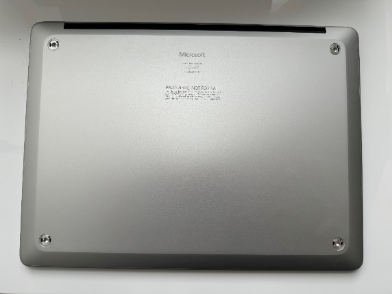
Place Device – Carefully place the closed device Display side down with the Feet facing up on a soft ESD-Safe Mat.
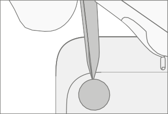
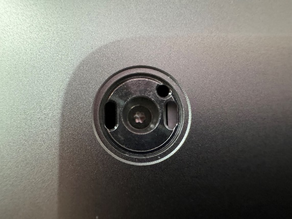
Remove the Feet – Using the Nylon Spudger, carefully pry up all four feet to expose the screws.
Procedure – Installation (Feet)
Install the Feet - Line up the posts on the Foot to the matching hole pattern on the Enclosure. Press firmly until the foot clicks into place. Repeat for the other 3 feet.
Enclosure Replacement
Preliminary Requirements
Important
Be sure to follow all special notes of caution within each process section.
- Device Serial Number Notation – The replacement Enclosure supplied for repair won't have a serial number. To ensure the customer has the best experience with future Microsoft support cases, it's recommended to create a notation of the device serial number and provide it to the customer upon completion of the repair.
Required Tools
Plastic Opening Pick
Soft ESD-Safe Mat
5IP (Torx-Plus) Driver
Primary Components
Enclosure (Refer to the Illustrated Service Parts List)
- M1301718 Screws x 4 (Foot screws)
Additional Components (Ordered Separately)
- Feet (Refer to the Illustrated Service Parts List)
Procedure – Removal (Enclosure)
Place Device – Carefully place the closed device Display side down with the Feet facing up on a soft ESD-Safe Mat.
Remove the Feet – Refer to the Procedure – Removal (Feet) section of this document for detailed instructions.
Remove the Enclosure screws – Using a 5IP (Torx-Plus) driver, uninstall each of the 4 screws from under the feet.
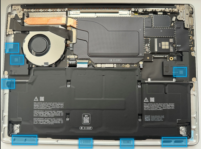
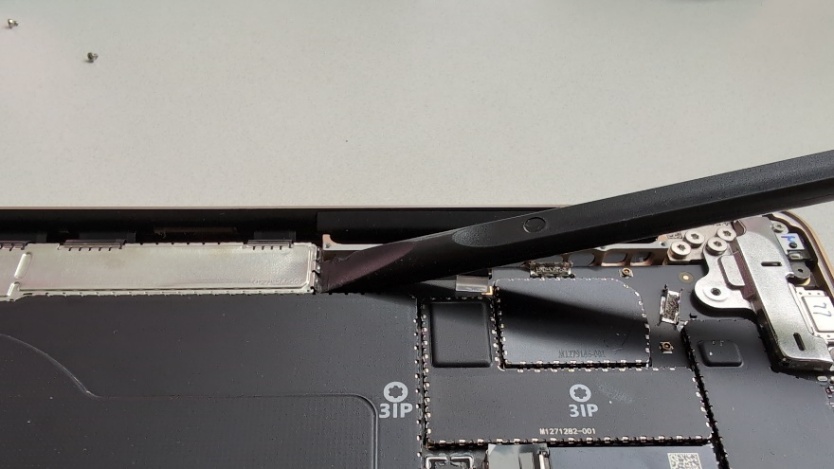
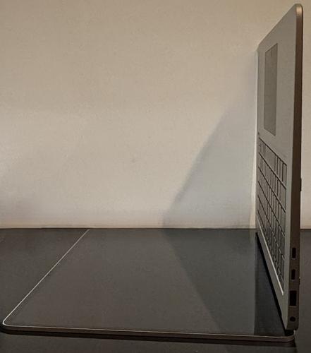
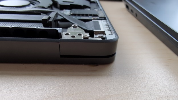
Separate the Enclosure from the Device – Carefully insert the tip of a Plastic Opening Pick into the space between the Enclosure and the Keyboard Assembly as shown below. Move the Plastic Opening Pick around the perimeter of the device to create a gap. Using both hands, carefully lift the Enclosure off the device and place it on a soft ESD-Safe mat.
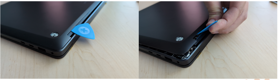
Caution
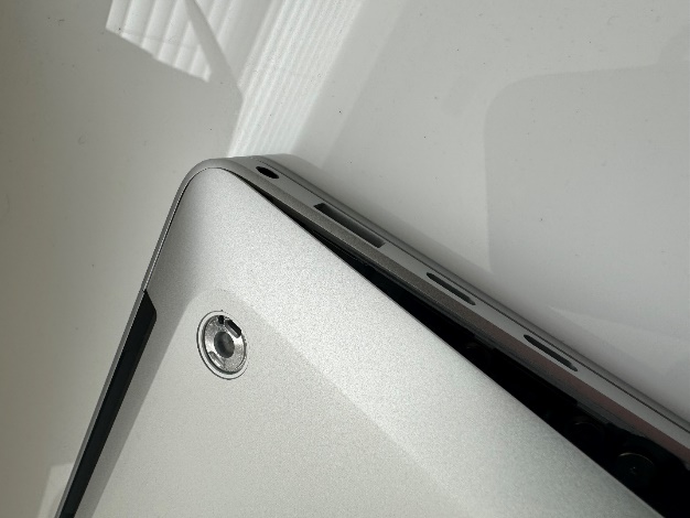
Do Not lift the Enclosure from the black plastic antenna.
Procedure – Installation (Enclosure)
Check for unexpected items within the Device - Perform a through visual inspection of the device interior, or Enclosure if re-using, for any loose articles that may be present. Of specific importance are the magnets (identified below).
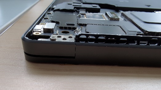
Install the Enclosure - Using both hands, carefully lower the top or bottom edge of the Enclosure onto the device ensuring you line it up against the top edge as shown below. Once aligned, lower the Enclosure into place on to the Device. Finally, adjust the position of the Enclosure so that the gaps are even on all sides, and none of the sides are catching when you press the Enclosure down flat.
Fasten the Enclosure - Using a 5IP (Torx-Plus) driver, install the 4 screws into the foot wells on the Enclosure. Each screw should be tightened until snug, and then turned another 45-degrees (1/8th turn) to fully fasten. Adjust the position of the Enclosure as you go to ensure even gaps around the perimeter.
Caution
Ensure that the Enclosure isn't stuck on a ledge as you're installing the screws. Shift the Enclosure as needed to avoid this condition.
Install the Feet – Refer to the Procedure – Installation (Feet) section of this document for detailed instructions.
Removable Solid-State Drive Replacement
Preliminary Requirements
Important
Be sure to follow all special notes of caution within each process section.
Required Tools
Plastic Opening Pick
Soft ESD-Safe Mat
5IP (Torx-Plus) Driver
Anti-Static wrist strap (1M Ohm resistance)
USB drive loaded with the Surface Diagnostic Toolkit
Primary Components
Removable Solid-State Drive (Refer to the Illustrated Service Parts List)
M1301718 Screws x 4 (Foot screws)
M1246215 Screws x 1 (Solid-State Drive)

Additional Components (Ordered Separately)
- Feet (Refer to the Illustrated Service Parts List)
Procedure – Removal (Removable Solid-State Drive)
Place Device – Carefully place the closed device Display side down with the Feet facing up on a soft ESD-Safe Mat.
Remove the Feet – Refer to the Procedure – Removal (Feet) section of this document for detailed instructions.
Remove the Enclosure – Refer to the Procedure – Removal (Enclosure) section of this document for detailed instructions.
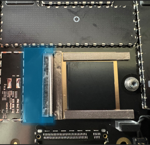
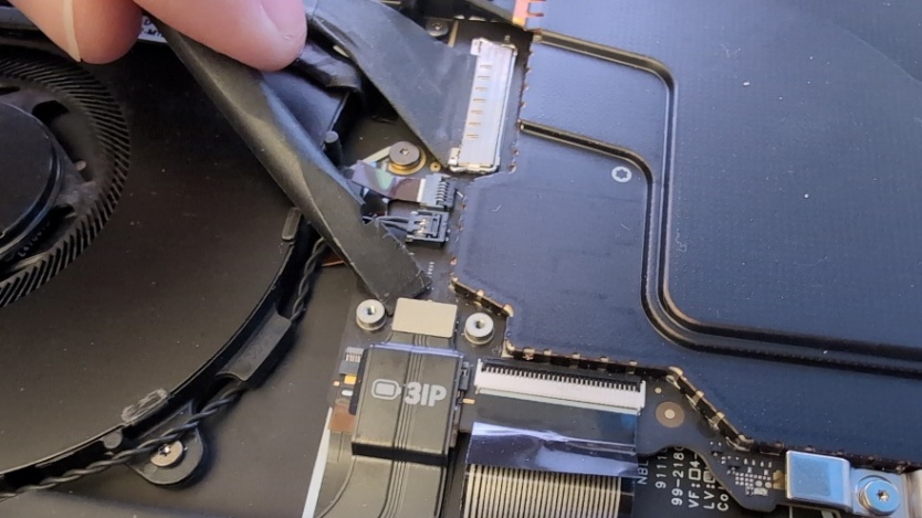
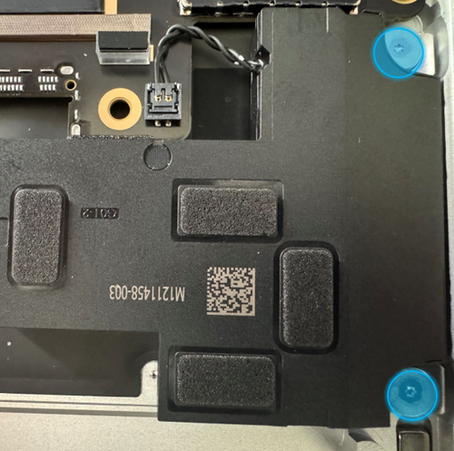
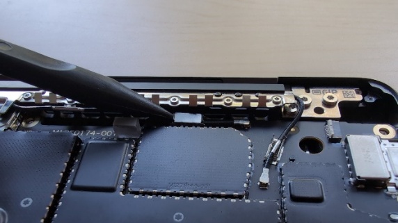
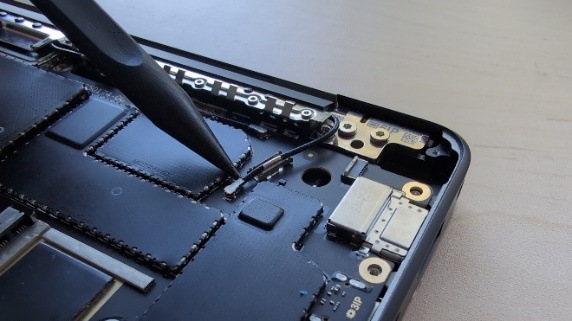
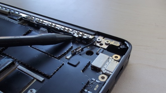
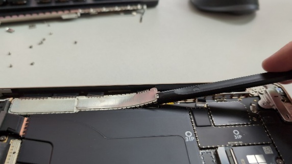
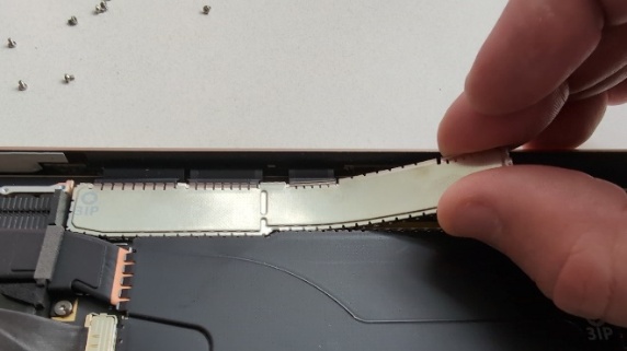
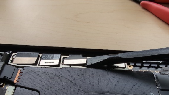
Remove the tape - Carefully peel up and completely remove the tape covering the Removable Solid-State Drive and the corresponding receptable. The gray spacer will also be removed along with the tape. Clean the top surfaces of the Removable Solid-State Drive and receptacle with IPA to remove any residual adhesive.
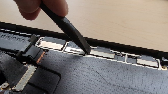
Remove the Removable Solid-State Drive – Using a 5IP (Torx-Plus) driver, remove the screw (
)
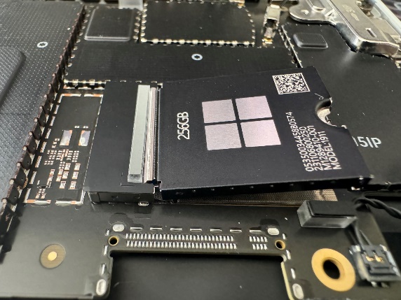
holding the Removable Solid-State Drive onto the Motherboard. Lift
the drive out of the device and place it on a soft ESD-Safe mat.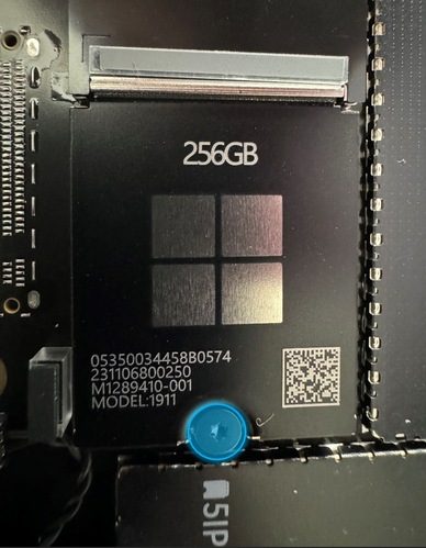
Procedure – Installation (Removable Solid-State Drive)
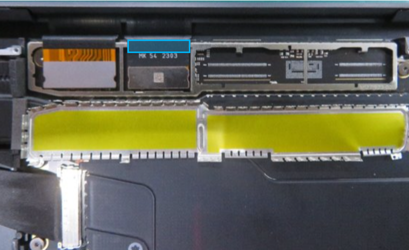
Insert the Removable Solid-State Drive – Carefully insert the connector end of the Removable Solid-State Drive into the receptable on the motherboard while keeping the Removable Solid-State Drive as close as possible to horizontal.
Caution
Ensure that the Speaker wire doesn't get caught or trapped when fastening the Removable Solid-State Drive to the Motherboard.
Install Removable Solid-State Drive screw – Using a 5IP (Torx-Plus) driver, install the 1 new rSSD screw (
)
until the screw is just snug. Then turn the screw an additional
45-degrees (1/8th turn) until screw is fully fastened.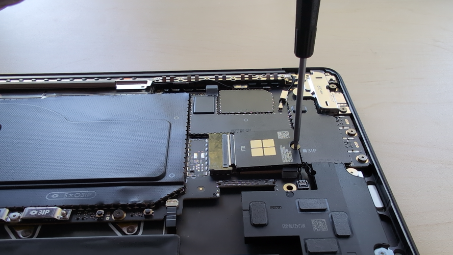
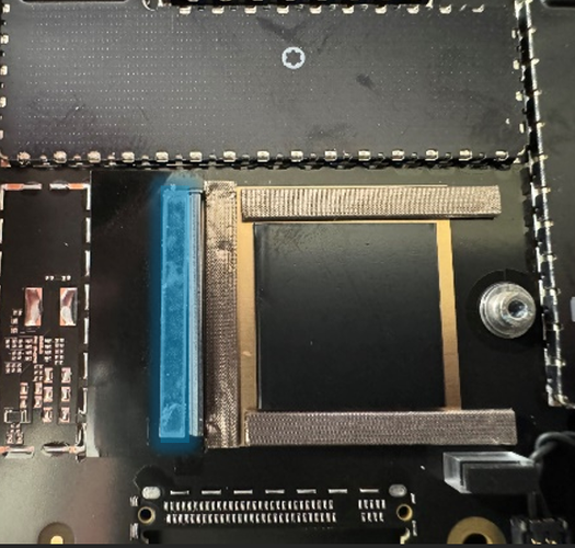
Install Black Tape on Motherboard Receptacle – Carefully place a new tape on the receptacle, making sure the cutout on the tape matches the shape of the raised flange on the receptacle.
Install Spacer – Place a new spacer on top of the Black Tape, parallel and as close as possible to the silver flange on the connector receptacle. Ensure the dot on one end of the spacer is oriented towards the display hinge and that the spacer is centered lengthwise with the silver flange.
Install Enclosure - Refer to the Procedure – Installation (Enclosure) section of this document for detailed instructions.
Power on device – Carefully place the device with the screen side facing up. Connect the device to a power supply and open the Display.
Image the device – Reinstall the operating system and all drivers/firmware by using a USB-drive containing the latest Surface BMR for your model. Please see the Surface Software Tools – Diagnostics, Calibration, Troubleshooting, and Support section for links to instructions on how to get the latest image and install it.
Run the Surface Diagnostic Toolkit (SDT) – With Windows installed and sitting at the desktop, insert the USB drive containing SDT and launch the program. Run all diagnostics to ensure the device is functioning as expected before moving forward.
Power off the device – Once the SDT tests have completed, power down the device and close the display. Invert the device so that the bottom of the device is facing up.
Install the Feet - Refer to the Procedure – Installation (Feet) section of this document for detailed instructions.
Battery Replacement
Preliminary Requirements
Important
Be sure to follow all special notes of caution within each process section.
Warning
Prior to handling the battery, the operator must remove all jewelry, wear gloves and safety glasses, and have a bucket of sand prepared in case of any battery event.
Warning
In the case of a battery event, submerge the entire device in sand. DO NOT attempt to pick up the device.
Required Tools
Plastic Opening Pick
Nylon Spudger
ESD-Safe Tweezers
Soft ESD-Safe Mat
5IP (Torx-Plus) Driver
3IP (Torx-Plus) Driver
Anti-Static wrist strap (1M Ohm resistance)
USB drive loaded with the Surface Diagnostic Toolkit
4 Gallon Bucket
2.0 Gallons of Clean Sand
Primary Components
Battery (Refer to the Illustrated Service Parts List)
M1301718 Screws x 4 (Foot screws)
M1246215 Screws x 1 (Solid-State Drive)
M1266593 Screws x 2 (Battery FPC Bracket)

M1272782 Screws x 8 (Battery)

Additional Components (Ordered Separately)
- Feet (Refer to the Illustrated Service Parts List)
Procedure – Preparation (Battery)
Important
This section is only for instances where you're replacing the battery. If the battery is being re-used, then this section isn't required.
Connect USB – Connect USB with the Surface Diagnostic Toolkit (SDT) loaded to an available USB port on the device under repair.
Power on device – Connect a power supply to the device. Press the power button on the device to power the device on. Allow it to boot to the Windows Desktop before continuing.
Launch SDT – From the Windows Desktop, use Windows Explorer to navigate to the USB drive. Select the SDT executable (.exe) to launch the Surface Diagnostic Toolkit.
Run Battery Repair (Setup) – From the SDT launch screen, select Repair from the drop-down menu. Next, select Repair Setup and Validation to enter the selection screen. Run the Battery Repair (Setup) to put your device into repair mode. Follow all on-screen instructions and allow the device to shut down when prompted. Disconnect the Power Supply and remove the USB drive before proceeding forward.
Procedure – Removal (Battery)
Place Device – Carefully place the closed device Display side down with the Feet facing up on a soft ESD-Safe Mat.
Remove the Feet – Refer to the Procedure – Removal (Feet) section of this document for detailed instructions.
Remove the Enclosure – Refer to the Procedure – Removal (Enclosure) section of this document for detailed instructions.
Remove the Removable Solid-State Drive - Refer to the Procedure – Removal (Removable Solid-State Drive) section of this document for detailed instructions.
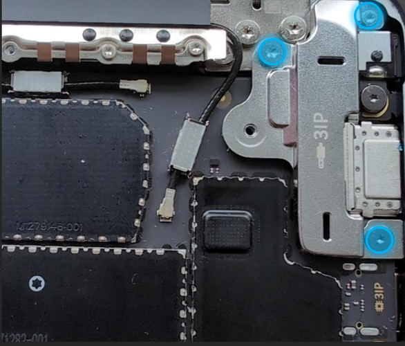
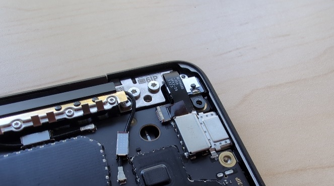
Remove the Battery Connector Metal Bracket – Using a 3IP (Torx-Plus) driver, remove the 2 screws (
) securing the metal bracket
to the motherboard. Lift the metal bracket out of the device to
expose the Battery FPC.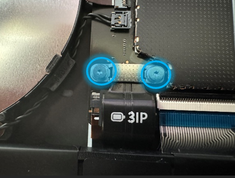
Disconnect the Battery FPC - Using a Nylon Spudger, pry the Battery FPC connector, starting from the side of the connector, from the Motherboard.
Remove the Battery Screws - Using a 5IP (Torx-Plus) driver, remove the 8 screws (
)
securing the Battery.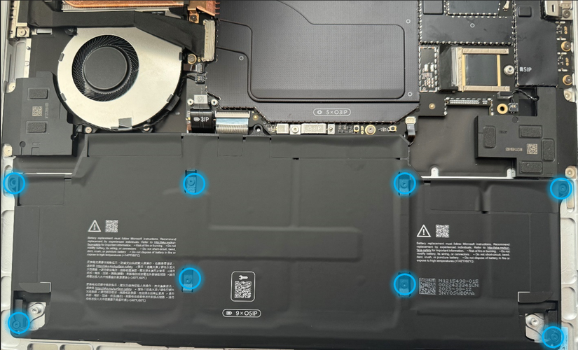
Remove the battery from the device - Using your hands, grab the battery at the four points identified below and carefully lift the battery out of the device. Place the battery on a clean ESD-Safe Mat free of any debris.
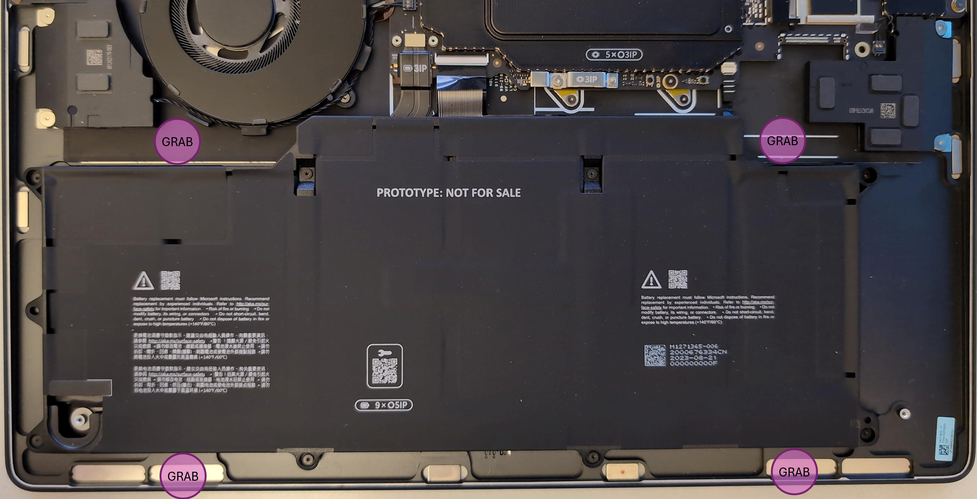
Warning
Only handle the battery by the plastic frame. Bending, twisting, or impacting the battery may damage the battery, the device, and/or result in severe personal injury or property damage. Always use two hands when handling the battery.
Important
Place the battery somewhere where the battery can't accidentally be contacted or damaged. DO NOT place anything on top of the battery.
Important
When disposing of the battery, ensure you're recycling according to local laws.
Important
The Motherboard Module and Battery are extremely sensitive to ESD and can be easily damaged. It's critical that you ensure proper grounding before performing any work on these parts.
Warning
In the instance of a battery event, submerge the entire device in a 4-gallon bucket filled with 2.0 gallons of clean sand. Ensure the entire device is submerged. DO NOT attempt to pick up the device.
Procedure – Installation (Battery)
Pre-installation device inspection – Check the device interior for any loose articles that may be present.
Check and remove any foreign objects that the magnets may have attracted.
Pay special attention to the magnetized areas around the edges of the interior.
Verify that all removed screws are accounted for and haven't been misplaced inside the device.
Loose screws should never be stored on the magnetic areas of the bucket.
Important
Verify the battery’s condition. Batteries exhibiting any damage indicated in the Lithium-Ion Battery Inspection section must be replaced.
Insert the Battery - Using the attached loops, carefully lower the battery into the new device.
Important
Only handle new batteries with the plastic loops that come attached. If reusing a battery, handle by the frame as indicated in the battery removal instructions. Bending, twisting, or impacting the battery may damage the battery, the device, and/or result in severe personal injury or property damage. Always use two hands when handling the battery.
Install the Battery screws - Using a 5IP screwdriver, install the 8 battery frame screws (
)
until the screws are just snug, then tighten each by an additional
45-degrees (1/8th turn).Important
Don't overtighten the screws on the battery frame or battery. If the frame is cracked, the battery must not be used.
Assemble the Battery FPC and FPC Bracket - Assemble the Battery FPC to the Motherboard. Using a 3IP (Torx-Plus) driver, install 2 FPC Bracket screws
until the screws are just
snug. Turn each screw an additional 45-degrees (1/8th
turn) until fully fastened.Install the Removable Solid-State Drive – Refer to Procedure – Installation (Removable Solid-State Drive) section of this document for detailed instructions.
Install the Enclosure – Refer to Procedure – Installation (Enclosure) section of this document for detailed instructions.
Procedure – Finalize (Battery)
Power on Device – Connect a Power Supply to the device and power it on until it reaches the Windows Desktop.
Connect USB – Connect USB with the Surface Diagnostic Toolkit (SDT) loaded to an available USB port on the device under repair.
Launch SDT – From the Windows Desktop, use Windows Explorer to navigate to the USB drive. Select the SDT executable (.exe) to launch the Surface Diagnostic Toolkit.
Allow the Battery to charge – With the device connected to a power supply, allow the battery to charge until the battery icon in Windows reads at least 50% remaining battery charge.
Run Battery Authentication – From the SDT launch screen, select Repair from the drop-down menu. Next, select Repair Setup and Validation to enter the selection screen. Select the Battery Repair (Validation) tool and follow the on-screen prompts until a successful authentication is completed.
Important
Battery authentication requires a stable internet connection and the latest version of the Surface Management Extension. If the battery validation tool fails or isn't detected properly, install the Surface Management Extension, reboot the device, and try again with a new internet connection. If failures continue, reach out to Microsoft Support.
Run the Surface Diagnostic Toolkit (SDT) – Run all diagnostics to ensure the device is functioning as expected before moving forward.
Install Feet – Refer to Procedure – Installation (Feet) section of this document for detailed instructions.
Audio Jack Replacement
Preliminary Requirements
Important
Be sure to follow all special notes of caution within each process section.
Required Tools
Plastic Opening Pick
Nylon Spudger
ESD-Safe Tweezers
Soft ESD-Safe Mat
6IP (Torx-Plus) Driver
5IP (Torx-Plus) Driver
3IP (Torx-Plus) Driver
Anti-Static wrist strap (1M Ohm resistance)
USB drive loaded with the Surface Diagnostic Toolkit
Primary Components
Audio Jack (Refer to the Illustrated Service Parts List)
M1301718 Screws x 4 (Foot screws)
M1246215 Screws x 1 (Solid-State Drive)
M1265600 Screws x 1 (Hinge & Chassis)

M1212080 Screws x 2 (Audio Jack Bridge)

M1263960 Screws x 1 (Audio Jack)

Additional Components (Ordered Separately)
- Feet (Refer to the Illustrated Service Parts List)
Procedure – Removal (Audio Jack)
Place Device – Carefully place the closed device Display side down with the Feet facing up on a soft ESD-Safe Mat.
Remove the Feet – Refer to the Procedure – Removal (Feet) section of this document for detailed instructions.
Remove the Enclosure – Refer to the Procedure – Removal (Enclosure) section of this document for detailed instructions.
Remove the Removable Solid-State Drive - Refer to the Procedure – Removal (Removable Solid-State Drive) section of this document for detailed instructions.
Remove the Audio Jack Bridge – Using a 3IP (Torx-Plus) and 6IP (Torx-Plus) driver, remove the 3 screws securing the Audio Jack Bridge to the interior. Lift the Audio Jack Bridge out of the device.
Remove the Audio Jack –
- Using a 3IP (Torx-Plus) screwdriver, remove the 1 screw securing the Audio Jack to the Motherboard.
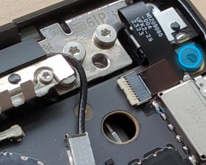
Using a Nylon Spudger, flip the latch on the Motherboard to disengage the lock on the Audio Jack FPC. Remove the Audio Jack FPC from the connector on the Motherboard.
Lift the Audio Jack out of the device.
Procedure – Installation (Audio Jack)
Install the Audio Jack –
Place the Audio Jack into its position on the Motherboard.
Make sure the latch on the Motherboard receptacle is in the vertical position.
Insert the Audio Jack FPC into the receptacle and flip the latch down.
Using a 3IP (Torx-Plus) driver to install a new Audio Jack screw (
)
until just snug. Then turn the screw an additional 45-degrees
(1/8th turn) until fully fastened.
Install the Audio Jack Bridge - Install the previously removed Audio Jack Bridge into its position over the Audio Jack. Using a 3IP (Torx-Plus) and 6IP (Torx-Plus) driver, install 3 new screws (2 x
,
All screws should be tightened until just snug, and then turned
another 45-degrees (1/8th turn) until fully fastened.Install the Removable Solid-State Drive – Refer to Procedure – Installation (Removable Solid-State Drive) section of this document for detailed instructions.
Install the Enclosure – Refer to Procedure – Installation (Enclosure) section of this document for detailed instructions.
Power on device – Carefully place the device with the screen side facing up. Connect the device to a power supply and open the Display.
Run the Surface Diagnostic Toolkit (SDT) – Sitting at the desktop, insert the USB drive containing SDT and launch the program. Run all diagnostics to ensure the device is functioning as expected before moving forward.
Power off the device – Once the SDT tests have completed, power down the device and close the display. Invert the device so that the bottom of the device is facing up.
Install the Feet - Refer to the Procedure – Installation (Feet) section of this document for detailed instructions.
Right Speaker Replacement
Preliminary Requirements
Important
Be sure to follow all special notes of caution within each process section.
Required Tools
Plastic Opening Pick
Nylon Spudger
ESD-Safe Tweezers
Soft ESD-Safe Mat
5IP (Torx-Plus) Driver
3IP (Torx-Plus) Driver
Anti-Static wrist strap (1M Ohm resistance)
USB drive loaded with the Surface Diagnostic Toolkit
Primary Components
Right Speaker (Refer to the Illustrated Service Parts List)
M1301718 Screws x 4 (Foot screws)
M1246215 Screws x 1 (Solid-State Drive)
M1211914 Screws x 2 (Speaker)
M1167842 Tape x 1 (Right Speaker Tape)
Additional Components (Ordered Separately)
- Feet (Refer to the Illustrated Service Parts List)
Procedure – Removal (Right Speaker)
Place Device – Carefully place the closed device Display side down with the Feet facing up on a soft ESD-Safe Mat.
Remove the Feet – Refer to the Procedure – Removal (Feet) section of this document for detailed instructions.
Remove the Enclosure – Refer to the Procedure – Removal (Enclosure) section of this document for detailed instructions.
Remove the Removable Solid-State Drive - Refer to the Procedure – Removal (Removable Solid-State Drive) section of this document for detailed instructions.
Remove the Speaker tape – Remove the tape and clean the surface with IPA to remove any residual adhesive.
Remove the Right Speaker screws – Using a 3IP (Torx-Plus) driver to remove the 2 screws securing the Right Speaker (which is on the left side when working on the device) to the Chassis.
Remove the Right Speaker – Remove the Right Speaker from the Chassis and de-route the cable. To remove the connector from the Motherboard, pull up vertically on the wireless until the connector comes free.
Procedure – Installation (Right Speaker)
Install the Right Speaker - Place the new Right Speaker into the Chassis. Using a 3IP (Torx-Plus) driver, install 2 new screws. All screws should be installed until just snug, and then turned another 45-degress (1/8th turn) until fully fastened.
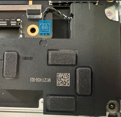
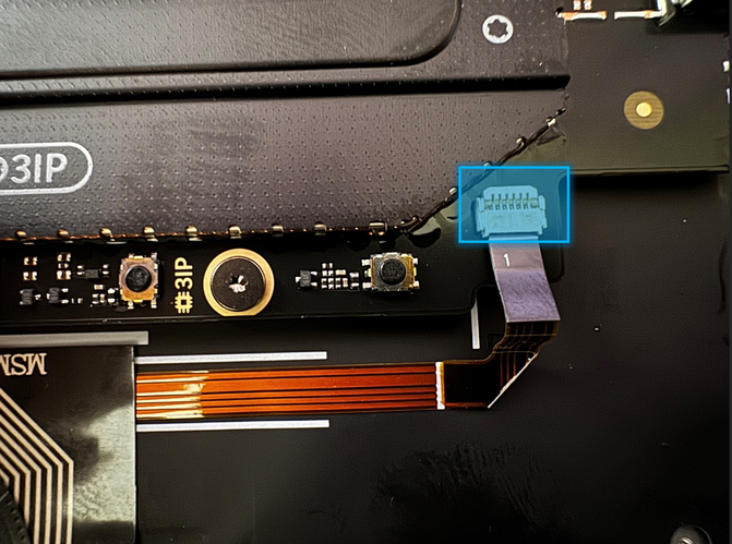
Route and connect the Right Speaker wire – Route the Right Speaker wire as shown below. Install the speaker connector into the receptacle on the Motherboard by pressing vertically until a snap is felt.
Note
The connector will have 2 visible gold contacts if it's oriented in the correct direction.
Place new Speaker Tape - Place a new Tape over the speaker wire as shown below.
Install the Removable Solid-State Drive – Refer to Procedure – Installation (Removable Solid-State Drive) section of this document for detailed instructions.
Install the Enclosure – Refer to Procedure – Installation (Enclosure) section of this document for detailed instructions.
Power on device – Carefully place the device with the screen side facing up. Connect the device to a power supply and open the Display.
Run the Surface Diagnostic Toolkit (SDT) – Sitting at the desktop, insert the USB drive containing SDT and launch the program. Run all diagnostics to ensure the device is functioning as expected before moving forward.
Power off the device – Once the SDT tests have completed, power down the device and close the display. Invert the device so that the bottom of the device is facing up.
Install the Feet - Refer to the Procedure – Installation (Feet) section of this document for detailed instructions.
Left Speaker Replacement
Preliminary Requirements
Important
Be sure to follow all special notes of caution within each process section.
Required Tools
Plastic Opening Pick
Nylon Spudger
ESD-Safe Tweezers
Soft ESD-Safe Mat
5IP (Torx-Plus) Driver
3IP (Torx-Plus) Driver
Anti-Static wrist strap (1M Ohm resistance)
USB drive loaded with the Surface Diagnostic Toolkit
Primary Components
Right Speaker (Refer to the Illustrated Service Parts List)
M1301718 Screws x 4 (Foot screws)
M1246215 Screws x 1 (Solid-State Drive)
M1211914 Screws x 2 (Speaker)
Additional Components (Ordered Separately)
- Feet (Refer to the Illustrated Service Parts List)
Procedure – Removal (Left Speaker)
Place Device – Carefully place the closed device Display side down with the Feet facing up on a soft ESD-Safe Mat.
Remove the Feet – Refer to the Procedure – Removal (Feet) section of this document for detailed instructions.
Remove the Enclosure – Refer to the Procedure – Removal (Enclosure) section of this document for detailed instructions.
Remove the Removable Solid-State Drive - Refer to the Procedure – Removal (Removable Solid-State Drive) section of this document for detailed instructions.
Remove the Left Speaker Screws – Using a 3IP (Torx-Plus), remove the 2 screws securing the Left Speaker, located on the Right side of the device when working on it, to the Chassis.
Remove the Left Speaker – Remove the Left Speaker from the Chassis. To Remove the connector from the Motherboard, pull up vertically on the wires until the connector comes free.
Procedure – Installation (Left Speaker)
Install the Left Speaker – Place the new Left Speaker into the Chassis. Using a 3IP (Torx-Plus) driver to install 2 new screws. All screws should be installed until just snug, and then turned another 45-degrees (1/8th turn) until fully fastened.
Connect the Left Speaker – Insert the speaker connector into the receptable on the Motherboard by pressing vertically until a snap is felt.
Note
The connector will have 2 visible gold contacts if it's oriented in the correct direction.
Install the Removable Solid-State Drive – Refer to Procedure – Installation (Removable Solid-State Drive) section of this document for detailed instructions.
Install the Enclosure – Refer to Procedure – Installation (Enclosure) section of this document for detailed instructions.
Power on device – Carefully place the device with the screen side facing up. Connect the device to a power supply and open the Display.
Run the Surface Diagnostic Toolkit (SDT) – Sitting at the desktop, insert the USB drive containing SDT and launch the program. Run all diagnostics to ensure the device is functioning as expected before moving forward.
Power off the device – Once the SDT tests have completed, power down the device and close the display. Invert the device so that the bottom of the device is facing up.
Install the Feet - Refer to the Procedure – Installation (Feet) section of this document for detailed instructions.
Micro SD Reader Replacement
Preliminary Requirements
Important
Be sure to follow all special notes of caution within each process section.
Required Tools
Plastic Opening Pick
Nylon Spudger
ESD-Safe Tweezers
Soft ESD-Safe Mat
5IP (Torx-Plus) Driver
3IP (Torx-Plus) Driver
Anti-Static wrist strap (1M Ohm resistance)
USB drive loaded with the Surface Diagnostic Toolkit
Primary Components
Micro SD (Refer to the Illustrated Service Parts List)
M1301718 Screws x 4 (Foot screws)
M1246215 Screws x 1 (Solid-State Drive)
M1235998 Screws x 2 (Micro SD)

Additional Components (Ordered Separately)
- Feet (Refer to the Illustrated Service Parts List)
Procedure – Removal (Micro SD Reader)
Place Device – Carefully place the closed device Display side down with the Feet facing up on a soft ESD-Safe Mat.
Remove the Feet – Refer to the Procedure – Removal (Feet) section of this document for detailed instructions.
Remove the Enclosure – Refer to the Procedure – Removal (Enclosure) section of this document for detailed instructions.
Remove the Removable Solid-State Drive - Refer to the Procedure – Removal (Removable Solid-State Drive) section of this document for detailed instructions.
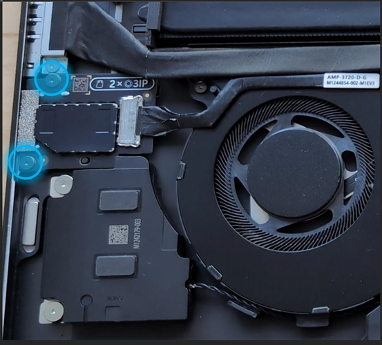
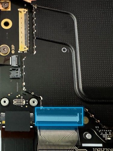
Disconnect the Micro SD Reader Cable – Using a Nylon Spudger, flip up the latch on the Micro SD Reader board and disconnect the connector.
Remove the Micro SD Reader – Using a 3IP (Torx-Plus) driver, remove the 2 screws holding the Micro SD Reader into the Chassis and lift the Micro SD Reader out of the device.
Procedure – Installation (Micro SD Reader)
Install the Micro SD Reader –
Carefully place the new Micro SD Reader into the device chassis.
Verify that the reader is aligned with the opening on the outside of the device chassis.
Using a 3IP (Torx-Plus) driver, install 2 new screws (
)
until just snug and then turn each another 45-degrees
(1/8th turn) until fully fastened.
Connect the Micro SD Reader Cable - Insert the Micro SD Reader cable into the receptacle on the Micro SD Reader board and close the latch. There should be a lick if the connector is inserted correctly, and the latch is fully closed.
Install the Removable Solid-State Drive – Refer to Procedure – Installation (Removable Solid-State Drive) section of this document for detailed instructions.
Install the Enclosure – Refer to Procedure – Installation (Enclosure) section of this document for detailed instructions.
Power on device – Carefully place the device with the screen side facing up. Connect the device to a power supply and open the Display.
Run the Surface Diagnostic Toolkit (SDT) – Sitting at the desktop, insert the USB drive containing SDT and launch the program. Run all diagnostics to ensure the device is functioning as expected before moving forward.
Power off the device – Once the SDT tests have completed, power down the device and close the display. Invert the device so that the bottom of the device is facing up.
Install the Feet - Refer to the Procedure – Installation (Feet) section of this document for detailed instructions.
Display Assembly Replacement
Preliminary Requirements
Important
Be sure to follow all special notes of caution within each process section.
Required Tools
Plastic Opening Pick
Nylon Spudger
ESD-Safe Tweezers
Soft ESD-Safe Mat
6IP (Torx-Plus) Driver
5IP (Torx-Plus) Driver
3IP (Torx-Plus) Driver
Anti-Static wrist strap (1M Ohm resistance)
USB drive loaded with the Surface Diagnostic Toolkit
Primary Components
Display Assembly (Refer to the Illustrated Service Parts List)
M1301718 Screws x 4 (Foot screws)
M1246215 Screws x 1 (Solid-State Drive)
M1265600 Screws x 8 (Hinge & Chassis)
M1274578 Screws x 12 (Antenna)
M1212080 Screws x 1 (Audio Jack Bridge)
M1263960 Screws x 2 (Audio Jack)
M1235995 Screws x 1 (Motherboard)
M1265416 Shield x 2 (Coax Cable Lid)
M1271924 Shield x 1 (T3 Shield)
M1288973 Foam x 1 (T3 Shield Foam #1)
M1288974 Foam x 1 (T3 Shield Foam #2)
M1291196 Tape x 1 (Display Assembly FPC Tape)
Additional Components (Ordered Separately)
- Feet (Refer to the Illustrated Service Parts List)
Procedure – Preparation (Display Assembly)
Important
This section is only for instances where you're replacing the Display. If the Display is being re-used, then this section isn't required. If Display is unusable due to damage or fault, connect an external monitor to the device to perform these steps.
Connect USB – Connect USB with the Surface Diagnostic Toolkit (SDT) loaded to an available USB port on the device under repair.
Power on device – Connect a power supply to the device. Press the power button on the device to power the device on. Allow it to boot to the Windows Desktop before continuing.
Launch SDT – From the Windows Desktop, use Windows Explorer to navigate to the USB drive. Select the SDT executable (.exe) to launch the Surface Diagnostic Toolkit.
Run Touch Display Setup – From the SDT launch screen, select Repair from the drop-down menu. Next, select Repair Setup and Validation to enter the selection screen. Run the Touch Display (Setup) tool to prepare your device for Display replacement. Follow all on-screen instructions and allow the device to shut down when prompted. Disconnect the Power Supply and remove the USB drive before proceeding forward.
Procedure – Removal (Display Assembly)
Place Device – Carefully place the closed device Display side down with the Feet facing up on a soft ESD-Safe Mat.
Remove the Feet – Refer to the Procedure – Removal (Feet) section of this document for detailed instructions.
Remove the Enclosure – Refer to the Procedure – Removal (Enclosure) section of this document for detailed instructions.
Remove the Removable Solid-State Drive - Refer to the Procedure – Removal (Removable Solid-State Drive) section of this document for detailed instructions.
Remove the Audio Jack - Refer to the Procedure – Removal (Audio Jack) section of this document for detailed instructions.
Remove the Antenna –
- Using a Nylon Spudger, pry up the 2 Coax Cable Lids.
Using a Nylon Spudger, disconnect the 2 Coax Cables.
Using a 3IP (Torx-Plus) driver, remove the 11 screws from the antenna.
Lift the Antenna out of the Chassis.
Remove the T3 Shield Lid –
- Using a Nylon Spudger, pry up the T3 Shield Lid starting with the right edge.
Note
Remove the Motherboard screw next to the T3 Shield can give better access for removal of the shield.
Slide the Nylon Spudger under the shield moving right to left. Pause and shift the shield up and down as you work your way left as the shield will get stuck on its latches.
Caution
Ensure that the shield doesn't damage the Display FPC’s during removal.
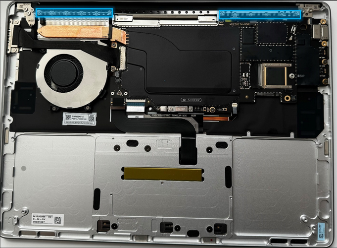
Disconnect the Display Assembly FPCs - Using a Nylon Spudger, pry up the connectors from the side and gently wiggle them free. If the connectors start giving resistance as they're being pried up, lightly push the edge being pried back down.
Caution
Don't force the connector if it starts to give resistance. Rock the connector back in the other direction to remove.
Reorient the Device –
Open the Display Assembly to 90 Degrees.
Place the backside of the Display Assembly on the ESD-Safe Mat with the screen and keyboard facing up.
Remove the Left Hinge Screws – With one hand holding the device still, use a 6IP (Torx-Plus) driver to remove the 3 screws on the Left Hinge.
Remove the Right Hinge Screws - With one hand holding the device still, use a 6IP (Torx-Plus) driver to remove the 4 screws on the Right Hinge.
Remove the Display Assembly from the Device - Carefully lift the Chassis from the Display Assembly. Place the Display Assembly on an ESD-Safe mat.
Procedure – Installation (Display Assembly)
Orient Display Assembly – Place the backside of the new Display Assembly on the ESD mat with each of the hinges set at 90-degree angles.
Install the new Display Assembly – Carefully align the hinges into the packets on the device Enclosure.
Important
Ensure the Enclosure doesn't impact on the display assembly glass.
Pre-fasten the right hinge screws - Using a 6IP (Torx-Plus) driver, install 4 new right side hinge screws (
)
and tighten until it's just snug.Pre-fasten the left hinge screws - Using a 6IP (Torx-Plus) driver, install 3 new left side hinge screws (
)
and tighten until just snug.Check alignment –
Close the device.
Loosen all 8 hinge screws 90 degrees (1/4th turn).
Adjust the alignment until the gap between the Display Assembly and the Chassis is as even as possible.
Tighten down 1 screw on the left hinge until snug. Adjust to the right side so that the Chassis surface is flush with the Display Assembly.
Tighten down 1 screw on the right hinge. Loosen the screw that was tightened down on the left hinge. Adjust the left side so that the Chassis surface is flush with the Display Assembly.
Repeat as necessary until the left and right gaps are even and the back surfaces are flush.
Tighten all hinge screws - Tighten all 7 hinge screws until they're snug, and then tighten an additional 90 degrees (1/4 turn) to ensure they're securely fastened.
Connect the Display Assembly FPCs to the Motherboard - Attach the display module cables to the receptacles on the Motherboard.
Place the Display Assembly FPC Tape – Place the Display Assembly FPC Tape to the Display Assembly FPC as shown.
Important
Tape should be applied only to the Display Assembly FPC.
Install the T3 Shield Foams (as needed) –
1.  If the Display Assembly being installed has 2 FPCs, inspect the
    shield fence for foams. If the foams aren't present, install
    the supplied foams as shown.

:::image type="content" source="./images/Laptop7/LT7Repair/media/t3-foam.png" alt-text="A close up of a device":::
If the Display Assembly being installed has 4 FPCs, inspect the shield fence for foams. Any foams on the shield fence should be removed.
Important
New Display Assemblies will only have 2 FPCs. The remaining 2 connections on the Motherboard will remain empty. This is by design.
Install the Motherboard screw - Using a 3IP (Torx-Plus) driver, install 1 new Motherboard screw (
 )
until just snug and seated, and then turn another 45-degrees
(1/8th turn) until fully fastened.
)
until just snug and seated, and then turn another 45-degrees
(1/8th turn) until fully fastened.Install the Antenna –
- Install the previously removed Antenna. Using a 3IP (Torx-Plus)
driver, install 12 new screws
(
 ).
All screws should be installed until just snug, and then turned
another 45-degrees (1/8th turn) until fully fastened.
).
All screws should be installed until just snug, and then turned
another 45-degrees (1/8th turn) until fully fastened.
- Install the previously removed Antenna. Using a 3IP (Torx-Plus)
driver, install 12 new screws
(
Connect the 2 Coax Cables to the Motherboard by aligning each with the socket, and pressing down until a click is felt.
Install 2 new Coax Cable Lids to the Motherboard over the Coax Cables. Align and press into place until a click is felt.
Install the Audio Jack – Refer to Procedure – Installation (Audio Jack) section of this document for detailed instructions.
Install the Removable Solid-State Drive – Refer to Procedure – Installation (Removable Solid-State Drive) section of this document for detailed instructions.
Install the Enclosure – Refer to Procedure – Installation (Enclosure) section of this document for detailed instructions.
Power on device – Carefully place the device with the screen side facing up. Connect the device to a power supply and open the Display.
Procedure – Finalize (Display Assembly)
Important
This section is only for instances where you're replacing the Display. If the Display is being re-used, then this section isn't required. If Display is unusable due to damage or fault, connect an external monitor to the device to perform these steps.
Connect USB – Connect USB with the Surface Diagnostic Toolkit (SDT) loaded to an available USB port on the device under repair.
Launch SDT – From the Windows Desktop, use Windows Explorer to navigate to the USB drive. Select the SDT executable (.exe) to launch the Surface Diagnostic Toolkit.
Run Touch Display Calibration – From the SDT launch screen, select Repair from the drop-down menu. Next, select Repair Setup and Validation to enter the selection screen. Run the Touch Display (Calibration) tool to calibrate your new Display. Follow all on-screen instructions and allow the device to restart when prompted.
Important
If the calibration fails, reboot the device, and attempt again. If the failure continues, then the Display may be faulty and require replacement.
Launch SDT – Once the device has rebooted and is at the Windows Desktop, use Windows Explorer to navigate to the USB drive. Select the SDT executable (.exe) to launch the Surface Diagnostic Toolkit.
Run the Surface Diagnostic Toolkit (SDT) – Run all diagnostics to ensure the device is functioning as expected before moving forward.
Install Feet – Refer to Feet Replacement for steps to install Feet.
Surface Connect Replacement
Preliminary Requirements
Important
Be sure to follow all special notes of caution within each process section.
Required Tools
Plastic Opening Pick
Nylon Spudger
ESD-Safe Tweezers
Soft ESD-Safe Mat
5IP (Torx-Plus) Driver
3IP (Torx-Plus) Driver
Isopropyl alcohol (91% or greater)
Cleaning swabs
Anti-Static wrist strap (1M Ohm resistance)
USB drive loaded with the Surface Diagnostic Toolkit
Primary Components
Surface Connect (Refer to the Illustrated Service Parts List)
M1301718 Screws x 4 (Foot screws)
M1246215 Screws x 1 (Solid-State Drive)
M1277572 Screws x 2 (Surface Connect)
M1301902 PSA x 1 (Surface Connect & Fan)
Additional Components (Ordered Separately)
- Feet (Refer to the Illustrated Service Parts List)
Procedure – Removal (Surface Connect)
Place Device – Carefully place the closed device Display side down with the Feet facing up on a soft ESD-Safe Mat.
Remove the Feet – Refer to the Procedure – Removal (Feet) section of this document for detailed instructions.
Remove the Enclosure – Refer to the Procedure – Removal (Enclosure) section of this document for detailed instructions.
Remove the Removable Solid-State Drive - Refer to the Procedure – Removal (Removable Solid-State Drive) section of this document for detailed instructions.
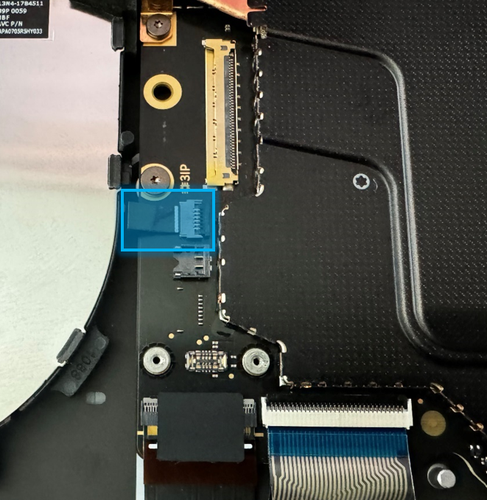
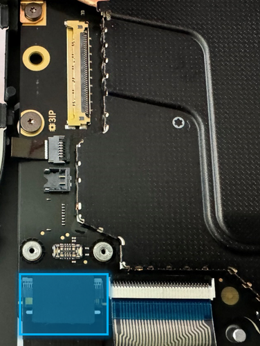
Disconnect the Surface Connect connector – Using a Nylon Spudger, flip up the latch on the Motherboard, and disconnect the Surface Connect connector from the Motherboard.
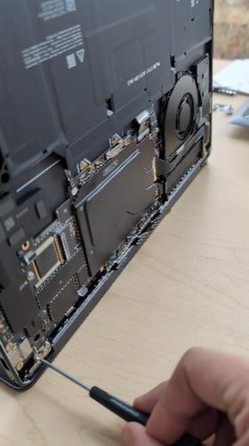
Remove the Surface Connect Cable - Using a 3IP (Torx-Plus) driver, remove the 2 screws securing the Surface Connect port to the Motherboard. Lift the cable out of the device and place it on an ESD-Safe mat.
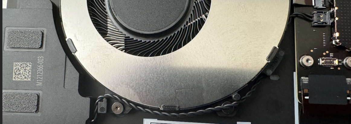
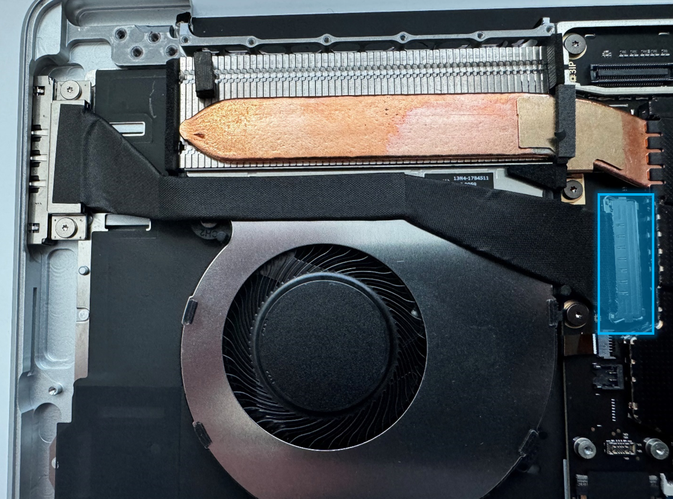
Remove residual adhesive - Gently peel up the PSA (pressure-sensitive adhesive) under the Surface Connect Cable (on the Fan) and remove. Clean up the surface with IPA and cleaning swabs until all residual adhesive has been removed and the surface is clean.
Procedure – Installation (Surface Connect)
Install new PSA - Place a new piece of PSA down onto the Fan as shown.
Install the Surface Connect Cable –
Insert the connector of the Surface Connect Cable into the receptacle on the Motherboard and close the latch to secure it. There should be a click if the connector is inserted correct and the latch is fully closed.
Toe in the Surface Connect connector into the device chassis ensuring that the plastic housing is flush with the outside surface of the chassis. The port should be fully aligned with the external opening.
Using a 3IP (Torx-Plus) driver, install the 2 new Surface Connect screws until the screw is just snug and seated, and then turn each another 45-degrees (1/8th turn) until fully fastened.
Lightly press the cable into the PSA to adhere the cable to the fan.
Install the Removable Solid-State Drive – Refer to Procedure – Installation (Removable Solid-State Drive) section of this document for detailed instructions.
Install the Enclosure – Refer to Procedure – Installation (Enclosure) section of this document for detailed instructions.
Power on device – Carefully place the device with the screen side facing up. Connect the device to a power supply and open the Display.
Run the Surface Diagnostic Toolkit (SDT) – Sitting at the desktop, insert the USB drive containing SDT and launch the program. Run all diagnostics to ensure the device is functioning as expected before moving forward.
Power off the device – Once the SDT tests have completed, power down the device and close the display. Invert the device so that the bottom of the device is facing up.
Install the Feet - Refer to the Procedure – Installation (Feet) section of this document for detailed instructions.
Motherboard Replacement Process
Preliminary Requirements
Important
Be sure to follow all special notes of caution within each process section.
Important
If replacing both the Motherboard and the Display Assembly – complete the Motherboard replacement prior to performing the Display Assembly Replacement to ensure proper part operation.
Required Tools
Plastic Opening Pick
Nylon Spudger
ESD-Safe Tweezers
Soft ESD-Safe Mat
6IP (Torx-Plus) Driver
5IP (Torx-Plus) Driver
3IP (Torx-Plus) Driver
Isopropyl alcohol (91% or greater)
Cleaning swabs
Anti-Static wrist strap (1M Ohm resistance)
USB drive loaded with the Surface Diagnostic Toolkit
Primary Components
Motherboard (Refer to the Illustrated Service Parts List)
M1301718 Screws x 4 (Foot screws)
M1266593 Screws x 2 (Battery FPC Bracket)
M1272782 Screws x 8 (Battery)
M1246215 Screws x 1 (Solid-State Drive)
M1265600 Screws x 1 (Hinge & Chassis)
M1274578 Screws x 14 (Antenna)
M1212080 Screws x 1 (Audio Jack Bridge)
M1263960 Screws x 2 (Audio Jack)
M1235995 Screws x 8 (Motherboard)
M1263961 Screws x 2 (Motherboard)

M1277573 Screws x 1 (Motherboard)

M1265416 Shield x 2 (Coax Cable Lid)
M1271279 Shield x 1 (T1 Shield
M1271924 Shield x 1 (T3 Shield)
M1288973 Foam x 1 (T3 Shield Foam #1)
M1288974 Foam x 1 (T3 Shield Foam #2)
M1287120 Tape x 1 (Touchpad FPC Tape)
M1019757 Syringe x 1 (Thermal Paste)
M1301902 PSA x 1 (Surface Connect & Fan)
Additional Components (Ordered Separately)
- Feet (Refer to the Illustrated Service Parts List)
Procedure – Removal (Motherboard)
Place Device – Carefully place the closed device Display side down with the Feet facing up on a soft ESD-Safe Mat.
Remove the Feet – Refer to the Procedure – Removal (Feet) section of this document for detailed instructions.
Remove the Enclosure – Refer to the Procedure – Removal (Enclosure) section of this document for detailed instructions.
Remove the Removable Solid-State Drive - Refer to the Procedure – Removal (Removable Solid-State Drive) section of this document for detailed instructions.
Remove the Audio Jack - Refer to the Procedure – Removal (Audio Jack) section of this document for detailed instructions.
Remove the Battery – Refer to the Procedure – Removal (Battery) section of this document for detailed instructions.
Remove the Antenna –
- Using a Nylon Spudger, pry up the 2 Coax Cable Lids.
Using a Nylon Spudger, disconnect the 2 Coax Cables.
Using a 3IP (Torx-Plus) driver, remove the 11 screws from the antenna.
Lift the Antenna out of the Chassis.
Remove the T3 Shield Lid –
- Using a Nylon Spudger, pry up the T3 Shield Lid starting with the right edge.
Note
Remove the Motherboard screw next to the T3 Shield can give better access for removal of the shield.
Slide the Nylon Spudger under the shield moving right to left. Pause and shift the shield up and down as you work your way left as the shield will get stuck on its latches.
Caution
Ensure that the shield doesn't damage the Display FPC’s during removal.
Disconnect the Display Assembly FPCs - Using a Nylon Spudger, pry up the connectors from the side and gently wiggle them free. If the connectors start giving resistance as they're being pried up, lightly push the edge being pried back down.
Caution
Don't force the connector if it starts to give resistance. Rock the connector back in the other direction to remove.
Remove the T1 Shield – Using a Nylon Spudger or ESD-Safe Tweezers, peel up the corner of the shield. Pry up the rest of the shield and remove.
Remove the T5 Shield - Using a Nylon Spudger or ESD-Safe Tweezers, peel up the corner of the shield. Pry up the rest of the shield and remove.
Disconnect the Surface Connect Cable – Using a Nylon Spudger, flip up the latch on the Motherboard and disconnect the Surface Connect connector from the Motherboard.
Disconnect the Microsoft SD Reader Cable – Using a Nylon Spudger, flip up the latch on the Micro SD Reader board and disconnect the connector from the Motherboard.
Remove Microsoft SD Reader Cable PSA on Fan - Peel up the Micro SD Reader cable from the Fan. Peel up and remove the PSA on the fan. Clean the surface with IPA and cleaning swabs until all residual adhesive is removed.
Remove the Surface Connect PSA on Fan - Peel up the Surface Connect cable from the Fan. Peel up and remove the PSA on the fan. Clean the surface with IPA and cleaning swabs until all residual adhesive is removed.
Disconnect the Fan FPC - Flip the latch on the Motherboard to disengage the lock on the Fan FPC. Remove the Fan FPC from the connector on the Motherboard.
Disconnect the Keyboard FPC - Flip the latch on the Motherboard to disengage the lock on the Keyboard FPC. Remove the Keyboard FPC from the connector on the Motherboard.
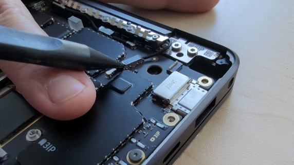
Disconnect the Touch FPC –
- Remove the black tape covering the Touchpad FPC and the connector. Clean the surface with IPA and cleaning swabs to ensure all residual adhesive is removed.
Flip the latch on the Motherboard to disengage the lock on the Touchpad FPC. Remove the Touchpad FPC from the connector on the Motherboard.
Disconnect the Keyboard Backlight FPC - Flip the latch on the Motherboard to disengage the lock on the Keyboard Backlight FPC. Remove the Keyboard Backlight FPC from the connector on the Motherboard.
Disconnect the Left Speaker - To remove the connector from the Motherboard, pull up vertically on the wires until the connector comes free.
Disconnect the Right Speaker - To remove the connector from the Motherboard, pull up vertically on the wires until the connector comes free.
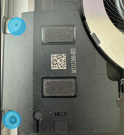
Remove the Motherboard Steel Bracket – Using a 3IP (Torx-Plus) Driver, remove the 1 screw holding the Motherboard Steel Bracket to the Enclosure.

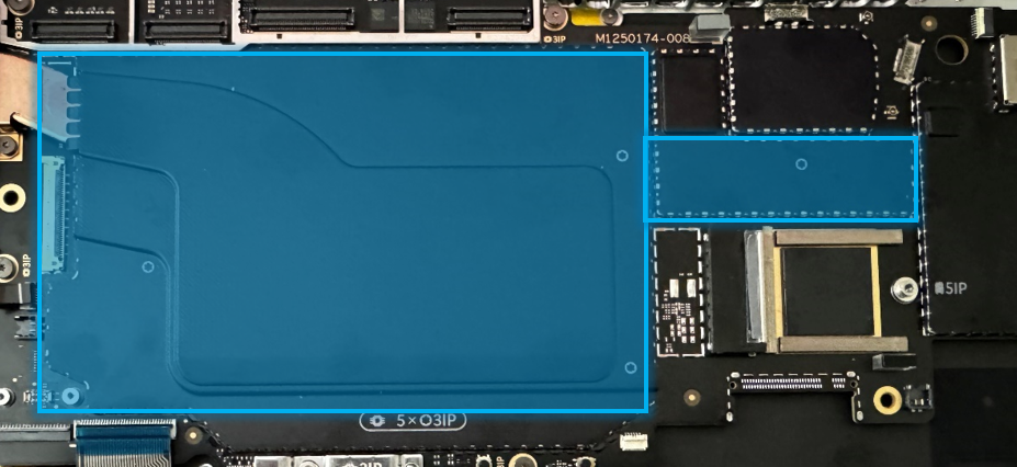
Remove the Motherboard Shields– Using ESD-Safe Tweezers, carefully remove the two metal shields identified below to expose the Motherboard screws underneath.
Remove the Motherboard Screws - Using a 3IP (Torx-Plus) driver, remove the 10 screws holding the Motherboard to the Chassis.
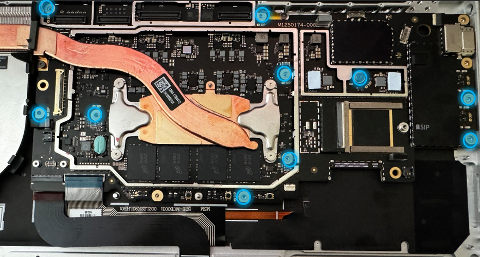
Remove the Motherboard – Using both hands, carefully lift the Motherboard out and up, taking care to avoid pulling on the thermal module or any connectors.
Procedure – Installation (Motherboard)
Install the Micro SD Reader Cable – Insert the Micro SD Reader Cable into the connector on the bottom side of the Motherboard.
Install the Motherboard –
Important
The Thermal Module should be installed onto the Motherboard. Take caution during installation of the Motherboard to avoid damage to the Thermal Module. Damage to the Thermal Module will require replacement of the Motherboard or device.
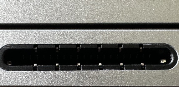
Lower the Motherboard USB-C side first into the device chassis. Ensure that the USB-C connectors fit in the corresponding holes in the Chassis.
Lower the left side of the Motherboard and use your other hand to keep the component FPCs out of the way.
Adjust the position of the Motherboard until all the hole’s line up with the screw bosses.
Using a 3IP (Torx-Plus) driver, install 8 new Motherboard screws (
)
until just snug. Turn each screw another 45-degrees
(1/8th turn) until fully fastened.
Using a 3IP (Torx-Plus) driver, install 2 new Motherboard screws (
)
until just snug. Turn each screw another 45-degrees
(1/8th turn) until fully fastened.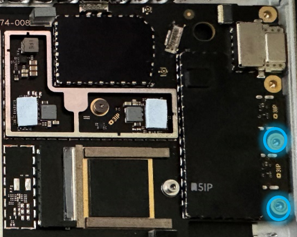
Important
Ensure that the slots next to the thermal module screws sit over the posts in the device chassis.
Assemble the T1 Shield –
- Using the provided syringe of thermal paste, apply the equivalent of 2 tick marks (marked on the side of the syringe) of thermal paste to the component marked below.
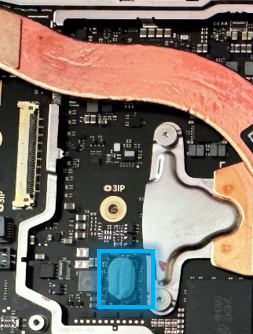
Using the same syringe of thermal paste, apply the equivalent of ½ ticket mark (marked on the side of the syringe) of thermal paste to the component marked below.
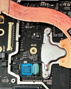
Assemble and install a new T1 Shield.
Assemble the Motherboard Steel Bracket - Using a 3IP (Torx-Plus) driver, install 1 new screw (
)
until just snug, and then turn another 45-degrees (1/8th
turn) until fully fastened.
Install the Removable Solid-State Drive – Refer to Procedure – Installation (Removable Solid-State Drive) section of this document for detailed instructions.
Connect the Fan FPC - Ensure the latch on the Motherboard receptable for the Fan FPC is in a vertical position before inserting the Fan FPC. Flip the latch on the Motherboard down to secure the Fan FPC.
Connect the Left Speaker wire - Insert the speaker connector into the receptable on the Motherboard by pressing vertically until a snap is felt.
Connect the Right Speaker wire - Insert the speaker connector into the receptable on the Motherboard by pressing vertically until a snap is felt.
Connect the Touchpad FPC -
Ensure the latch on the Motherboard connector for the Touchpad FPC is in the vertical position before inserting the Touchpad FPC. Flip the latch on the Motherboard down to secure the Touchpad FPC.
Apply a new Touchpad FPC Tape across the FPC and the Motherboard connector.
Connect the Keyboard FPC - Ensure the latch on the Motherboard connector for the Keyboard FPC is in a vertical position before inserting the Keyboard FPC. Flip the latch on the Motherboard down to secure the Keyboard FPC.
Connect the Keyset Backlight FPC - Ensure the latch on the Motherboard connector for the Keyset Backlight FPC is in a vertical position before inserting the Keyset Backlight FPC. Flip the latch on the Motherboard down to secure the Keyset Backlight FPC.
Connect the Audio Jack FPC - Ensure the latch on the Motherboard connector for the Audio Jack FPC is in the vertical position before inserting the Audio Jack FPC. Flip the latch on the Motherboard down to secure the Audio Jack FPC.
Install new PSA - Place a new piece of PSA down onto the Fan as shown.
Install the Surface Connect Cable – Insert the connector of the Surface Connect Cable into the receptacle on the Motherboard and close the latch to secure it. There should be a click if the connector is inserted correct and the latch is fully closed.
Install the Display Assembly FPC’s, T3 Shield, and Antenna - Refer to the Procedure – Installation (Display Assembly) section of this document for detailed instructions.
Install the Audio Jack - Refer to the Procedure – Installation (Audio Jack) section of this document for detailed instructions.
Install the Battery - Refer to the Procedure – Installation (Battery) section of this document for detailed instructions.
Install the Enclosure – Refer to Procedure – Installation (Enclosure) section of this document for detailed instructions.
Procedure – Finalize (Motherboard)
Important
If replacing both the Motherboard Module and the Display Assembly – complete the Motherboard Module replacement prior to performing the Display Assembly Replacement to ensure proper part operation.
Power on Device – Connect a Power Supply to the device and power it on until it reaches the Windows Desktop.
Connect USB – Connect USB with the Surface Diagnostic Toolkit (SDT) loaded to an available USB port on the device under repair.
Launch SDT – From the Windows Desktop, use Windows Explorer to navigate to the USB drive. Select the SDT executable (.exe) to launch the Surface Diagnostic Toolkit.
Run Touch Display Calibration – From the SDT launch screen, select Repair from the drop-down menu. Next, select Repair Setup and Validation to enter the selection screen. Run the Touch Display (Calibration) tool to calibrate your new Display. Follow all on-screen instructions and allow the device to restart when prompted.
Important
If the calibration fails, reboot the device, and attempt again. If the failure continues, then the Display may be faulty and require replacement.
Allow the Battery to charge – With the device connected to a power supply, allow the battery to charge until the battery icon in Windows reads at least 50% remaining battery charge.
Launch SDT – Once the device has rebooted and is at the Windows Desktop, use Windows Explorer to navigate to the USB drive. Select the SDT executable (.exe) to launch the Surface Diagnostic Toolkit.
Run Battery Authentication – From the SDT launch screen, select Repair from the drop-down menu. Next, select Repair Setup and Validation to enter the selection screen. Select the Battery Repair (Validation) tool to ensure the battery is detected as properly authenticated. If the battery reads anything other than authenticated, run the Validation tool in its entirety.
Important
Battery authentication requires a stable internet connection and the latest version of the Surface Management Extension. If the battery validation tool fails or isn't detected properly, install the Surface Management Extension, reboot the device, and try again with a new internet connection. If failures continue, reach out to Microsoft Support.
Run the Surface Diagnostic Toolkit (SDT) – Run all diagnostics to ensure the device is functioning as expected before moving forward.
Install Feet – Refer to Feet Replacement for steps to install Feet.
Keyboard Replacement Process
Preliminary Requirements
Important
Be sure to follow all special notes of caution within each process section.
Required Tools
Plastic Opening Pick
Nylon Spudger
ESD-Safe Tweezers
Soft ESD-Safe Mat
6IP (Torx-Plus) Driver
5IP (Torx-Plus) Driver
3IP (Torx-Plus) Driver
2IP (Torx-Plus) Driver
Isopropyl alcohol (91% or greater)
Cleaning swabs
Anti-Static wrist strap (1M Ohm resistance)
USB drive loaded with the Surface Diagnostic Toolkit
Primary Components
Keyboard Assembly (Refer to the Illustrated Service Parts List)
M1301718 Screws x 4 (Foot screws)
M1266593 Screws x 2 (Battery FPC Bracket)
M1272782 Screws x 8 (Battery)
M1246215 Screws x 1 (Solid-State Drive)
M1265600 Screws x 1 (Hinge & Chassis)
M1274578 Screws x 14 (Antenna)
M1212080 Screws x 1 (Audio Jack Bridge)
M1263960 Screws x 2 (Audio Jack)
M1235995 Screws x 8 (Motherboard)
M1263961 Screws x 2 (Motherboard)
M1277573 Screws x 1 (Motherboard)
M1211014 Screws x 4 (Speakers)
M1277572 Screws x 2 (Surface Connect)
M1235134 Screws x 3 (Fan)
M1249236 Screws x 4 (Mounting Brackets)
M1265416 Shield x 2 (Coax Cable Lid)
M1271279 Shield x 1 (T1 Shield
M1271924 Shield x 1 (T3 Shield)
M1288973 Foam x 1 (T3 Shield Foam #1)
M1288974 Foam x 1 (T3 Shield Foam #2)
M1287120 Tape x 1 (Touchpad FPC Tape)
M1167842 Tape x 1 (Right Speaker Tape)
M1019757 Syringe x 1 (Thermal Paste)
M1301902 PSA x 1 (Surface Connect & Fan)
Additional Components (Ordered Separately)
- Feet (Refer to the Illustrated Service Parts List)
Procedure – Removal (Keyboard Assembly)
Place Device – Carefully place the closed device Display side down with the Feet facing up on a soft ESD-Safe Mat.
Remove the Feet – Refer to the Procedure – Removal (Feet) section of this document for detailed instructions.
Remove the Enclosure – Refer to the Procedure – Removal (Enclosure) section of this document for detailed instructions.
Remove the Removable Solid-State Drive - Refer to the Procedure – Removal (Removable Solid-State Drive) section of this document for detailed instructions.
Remove the Audio Jack - Refer to the Procedure – Removal (Audio Jack) section of this document for detailed instructions.
Remove the Battery – Refer to the Procedure – Removal (Battery) section of this document for detailed instructions.
Remove the Left Speaker – Refer to the Procedure – Removal (Left Speaker) section of this document for detailed instructions.
Remove the Right Speaker - Refer to the Procedure – Removal (Right Speaker) section of this document for detailed instructions.
Remove the Micro SD Reader – Refer to the Procedure – Removal (Micro SD Reader) section of this document for detailed instructions.
Remove the Display Assembly – Refer to the Procedure – Removal (Display Assembly) section of this document for detailed instructions.
Remove the Surface Connect – Refer to the Procedure – Removal (Surface Connect) section of this document for detailed instructions.
Remove the Motherboard - Refer to the Procedure – Removal (Motherboard) section of this document for detailed instructions.
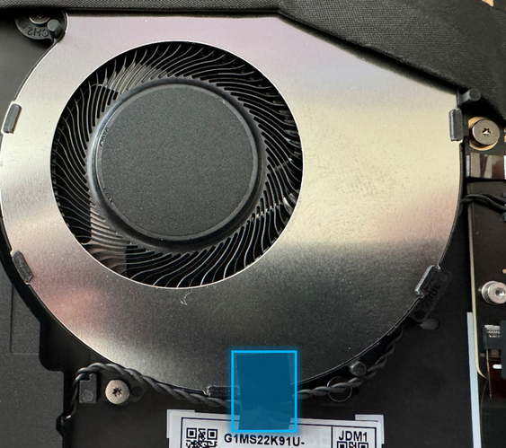
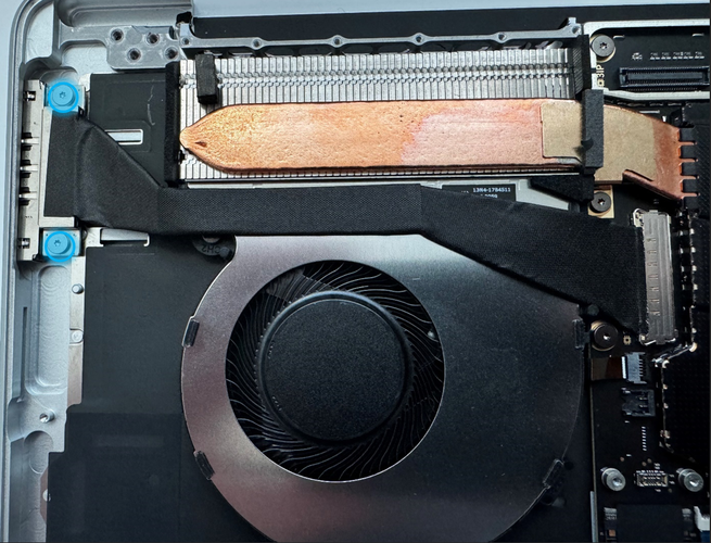
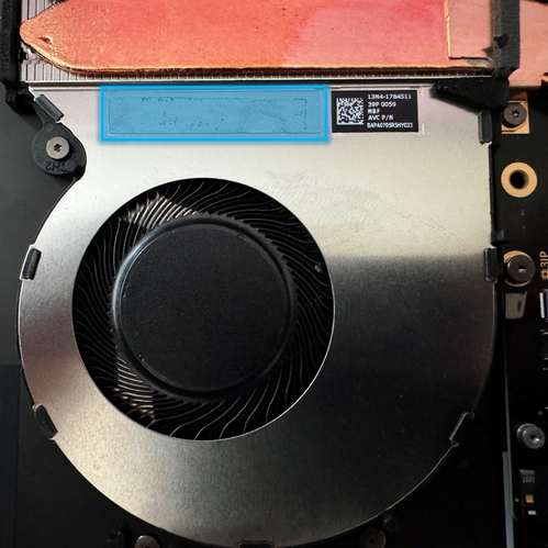
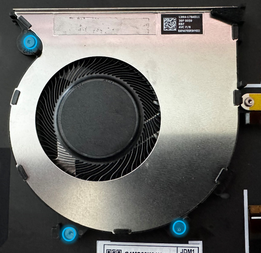
Remove the Fan – Using a 3IP (Torx-Plus) driver, remove the 3 screws securing the Fan to the Keyboard Assembly. Remove the Fan from the device.
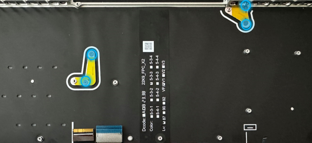
Remove the Mounting Brackets– Using a 2IP (Torx-Plus) driver, remove the 2 screws holding each of the Mounting Brackets to the Keyboard Assembly. Remove the 2 Mounting Brackets from the device.
Procedure – Installation (Keyboard Assembly)
Install the Mounting Brackets –
- Place the 2 previously removed Mounting Brackets so that the yellow side is visible, and they're arranged as shown here.
Using a 2IP (Torx-Plus) driver, install 4 new Mounting Bracket screws until the screws are just snug, and then turn each another 45-degrees (1/8th turn) until fully fastened.
Install the Motherboard - Refer to the Procedure – Installation (Motherboard) section of this document for detailed instructions. Complete steps 1-4 in that section.
Install the Removable Solid-State Drive – Refer to Procedure – Installation (Removable Solid-State Drive) section of this document for detailed instructions.
Install the Fan -
- Using a 3IP (Torx-Plus) driver, install 3 new Fan screws until they're just snug, and then turn each another 45-degrees (1/8th turn) until fully fastened.
Ensure the latch on the Motherboard connector for the Fan is in a vertical position before inserting the Fan FPC. Flip the latch down to secure the Fan FPC.
Install the Left Speaker - Refer to Procedure – Installation (Left Speaker) section of this document for detailed instructions.
Install the Right Speaker - Refer to Procedure – Installation (Right Speaker) section of this document for detailed instructions.
Continue with Motherboard installation - Refer to the Procedure – Installation (Motherboard) section of this document for detailed instructions. You'll start at Step 6.
Install the Display - Refer to the Procedure – Installation (Display) section of this document for detailed instructions.
Install the Audio Jack - Refer to the Procedure – Installation (Audio Jack) section of this document for detailed instructions.
Install the Surface Connect - Refer to the Procedure – Installation (Surface Connect) section of this document for detailed instructions.
Install the Battery - Refer to the Procedure – Installation (Battery) section of this document for detailed instructions.
Install the Enclosure - Refer to the Procedure – Installation (Enclosure) section of this document for detailed instructions.
Power on device – Carefully place the device with the screen side facing up. Connect the device to a power supply and open the Display.
Run the Surface Diagnostic Toolkit (SDT) – Sitting at the desktop, insert the USB drive containing SDT and launch the program. Run all diagnostics to ensure the device is functioning as expected before moving forward.
Power off the device – Once the SDT tests have completed, power down the device and close the display. Invert the device so that the bottom of the device is facing up.
Install the Feet - Refer to the Procedure – Installation (Feet) section of this document for detailed instructions.