Deploy Active Directory Federation Services in Azure
Active Directory Federation Services (AD FS) provides simplified, secured identity federation and web single sign-on (SSO) capabilities. Users federated with Microsoft Entra ID or Microsoft 365 can authenticate using on-premises credentials to access all cloud resources. As a result, your deployment must have a highly available AD FS infrastructure to ensure access to resources both on-premises and in the cloud.
Deploying AD FS in Azure can help achieve high availability without too much effort. There are several advantages of deploying AD FS in Azure:
- The power of Azure availability sets gives you a highly available infrastructure.
- Deployments are easy to scale. If you need more performance, you can easily migrate to more powerful machines using a simplified deployment process in Azure.
- Azure geo redundancy ensures your infrastructure is highly available across the globe.
- The Azure portal makes your infrastructure easier to manage with highly simplified management options.
Design principles
The following diagram shows the recommended basic topology for deploying AD FS infrastructure in Azure.
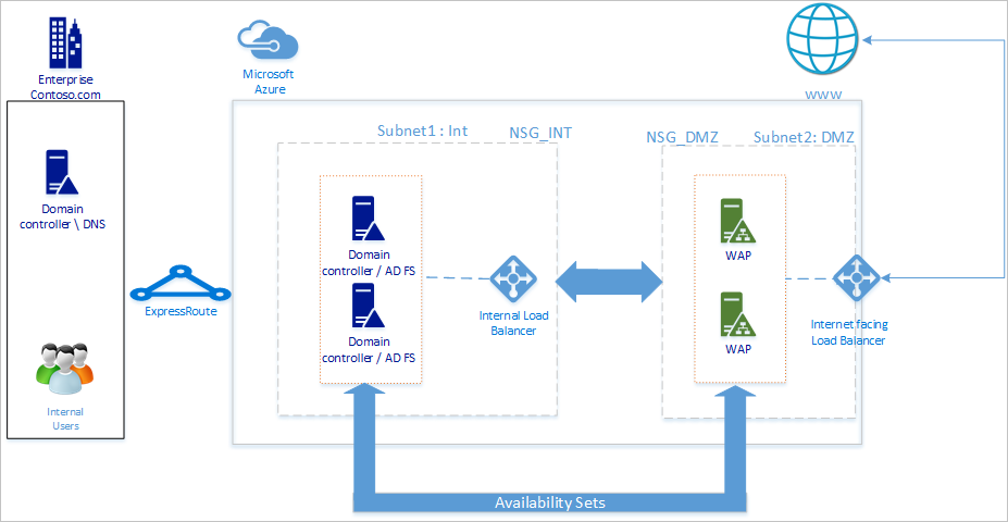
We recommend your network topology follows these general principles:
- Deploy AD FS on separate servers to avoid affecting the performance of your domain controllers.
- You must deploy web application proxy (WAP) servers so that users can reach the AD FS when they aren't on the company network.
- You should set up the web application proxy servers in the demilitarized zone (DMZ) and only allow TCP/443 access between the DMZ and internal subnet.
- To ensure high availability of AD FS and web application proxy servers, we recommend using an internal load balancer for AD FS servers and Azure Load Balancer for web application proxy servers.
- To provide redundancy to your AD FS deployment, we recommend that you group two or more virtual machines (VMs) in an availability set for similar workloads. This configuration ensures that during either a planned or unplanned maintenance event, at least one VM is available.
- You should deploy web application proxy servers in a separate DMZ network. You can divide one virtual network into two subnets and then deploy the web application proxy servers in an isolated subnet. You can configure the network security group settings for each subnet and allow only required communication between the two subnets.
Deploy the network
When creating a network, you can either create two subnets in the same virtual network or create two different virtual networks. We recommend using the single-network approach, as creating two separate virtual networks also requires creating two separate virtual network gateways for communication purposes.
Create a virtual network
To create a virtual network:
Sign in to the Azure portal with your Azure account.
In the portal, search for and select Virtual networks.
On the Virtual networks page, select + Create.
In Create virtual network, go to the Basics tab and configure the following settings:
Configure the following settings under Project details:
For Subscription, select the name of your subscription.
For Resource group, either select the name of an existing resource group or select Create new to make a new one.
Configure the following settings for Instance details:
For Virtual network name, enter a name for your virtual network.
For Region, select the region you want to create your virtual network in.
Select Next.
In the Security tab, enable any security service you want to use, then select Next.
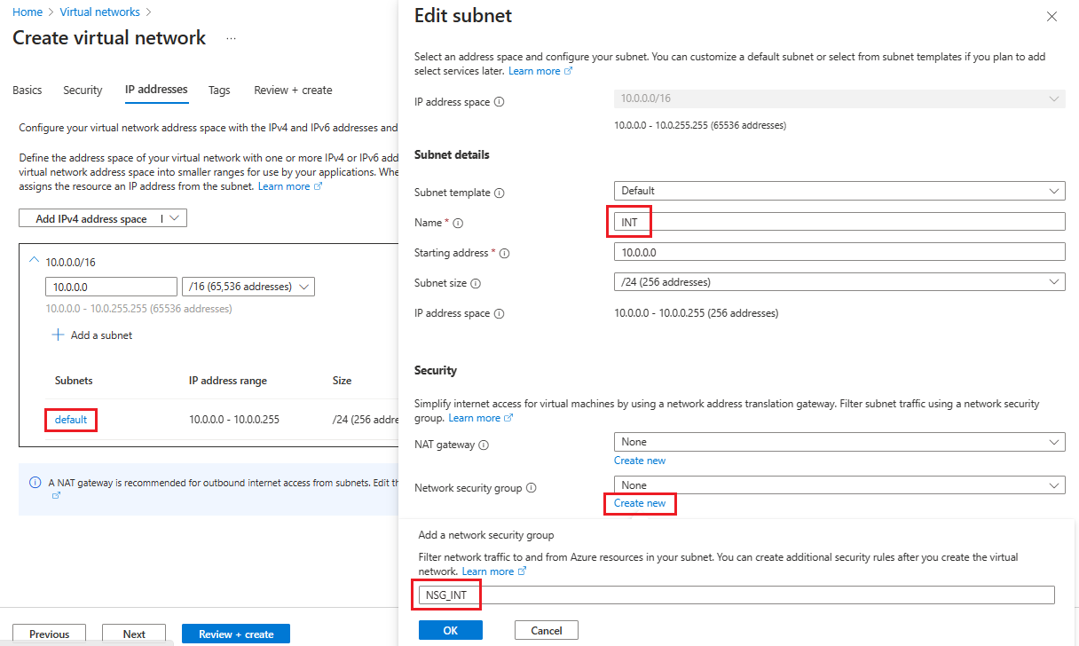
On the IP addresses tab, select the name of the subnet you want to edit. For this example, we're editing the default subnet that the service automatically creates.
On the Edit subnet page, rename the subnet to INT.
Enter the IP address and Subnet size information for your subnet to define an IP address space.
For Network security group, select Create new.
For this example, enter the name NSG_INT and select OK, then select Save. You now have your first subnet.
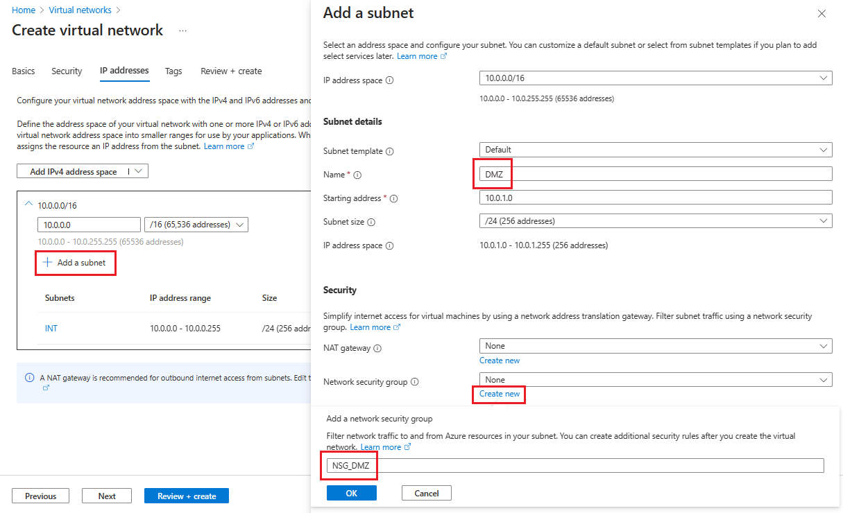
To create your second subnet, select + Add a subnet.
On the Add a subnet page, enter DMZ for the second subnet name, then enter information about your subnet into the empty fields to define an IP address space.
For Network security group, select Create new.
Enter the name NSG_DMZ, select OK, then select Add.
Select Review + create, then select Create.
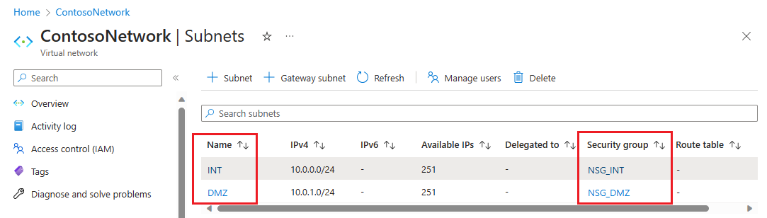
You now have a virtual network that includes two subnets, each with an associated network security group.
Secure the virtual network
A Network security group (NSG) contains a list of Access Control List (ACL) rules that allow or deny network traffic to your VM instances in a virtual network. You can associate NSGs with either subnets or individual VM instances within that subnet. When an NSG is associated with a subnet, the ACL rules apply to all the VM instances in that subnet.
The NSGs associated with your subnets automatically include some default inbound and outbound rules. You can't delete default security rules, but you can override them with rules that have a higher priority. And, you can add more inbound and outbound rules according to the level of security you want.
Now, add a couple of rules to each of our two security groups. For the first example, let's add an inbound security rule to the NSG_INT security group.
On your virtual network's Subnets page, select NSG_INT.
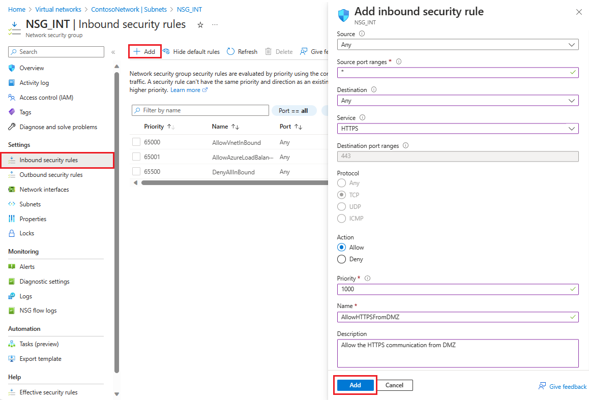
On the left, select Inbound security rules, then select + Add.
In Add inbound security rule, configure the rule with the following information:
For Source, enter 10.0.1.0/24.
For the Source port ranges, either leave it blank if you don't want to allow traffic or select an asterisk (*) to allow traffic on any port.
For Destination, enter 10.0.0.0/24.
For Service, select HTTPS. The service automatically fills the information fields for Destination port ranges and Protocol depending on which service you choose.
For Action, select Allow.
For Priority, enter 1010.
For Name, enter AllowHTTPSFromDMZ.
For Description, enter Allow the HTTPS communication from DMZ.
After you're finished, select Add.
 The new inbound security rule is now added to the top of the list of rules for NSG_INT.
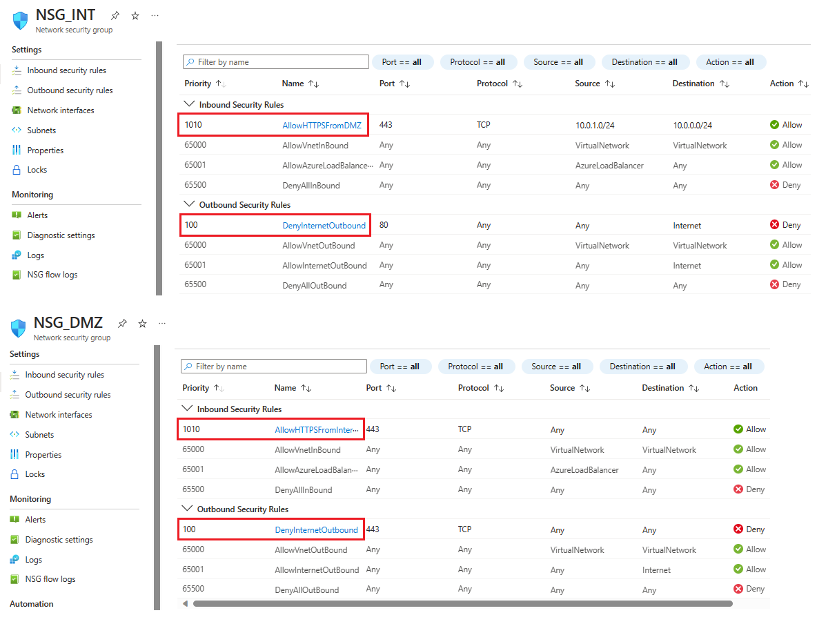
Repeat these steps with the values shown in the following table. In addition to the new rule you created, you must add the following extra rules in the priority order listed to help secure your internal and DMZ subnet.
NSG Type of rule Source Destination Service Action Priority Name Description NSG_INT Outbound Any Service Tag/Internet Custom (80/Any) Deny 100 DenyInternetOutbound No access to internet. NSG_DMZ Inbound Any Any Custom (Asterisk (*)/Any) Allow 1010 AllowHTTPSFromInternet Allow HTTPS from internet to the DMZ. NSG_DMZ Outbound Any Service Tag/Internet Custom (80/Any) Deny 100 DenyInternetOutbound Anything except HTTPS to internet is blocked. After you finish entering the values for each new rule, select Add and proceed to the next until two new security rules are added for each NSG.
After configuration, the NSG pages should look like the following screenshot:
Note
If the virtual network requires client user certificate authentication, such as clientTLS authentication using X.509 user certificates, you must enable TCP port 49443 for inbound access.
Create connection to on-premises
You need a connection to on-premises to deploy the DC in Azure. You can connect your on-premises infrastructure to your Azure infrastructure using one of the following options:
- Point-to-site
- Virtual Network site-to-site
- ExpressRoute
We recommend you use ExpressRoute if your organization doesn't require point-to-site or Virtual Network site-to-site connections. ExpressRoute lets you create private connections between Azure datacenters and infrastructure that's on your premises or in a colocation environment. ExpressRoute connections also don't connect to the public internet, which makes them more reliable, faster, and more secure. To learn more about ExpressRoute and the various connectivity options using ExpressRoute, read ExpressRoute technical overview.
Create availability sets
For each role (DC/AD FS and WAP), create availability sets that contain at least two machines each. This configuration helps achieve higher availability for each role. While creating the availability sets, you must decide which of the following domains you want to use:
In a fault domain, VMs share the same power source and physical network switch. We recommend a minimum of two fault domains. The default value is 2 and you can leave it as-is for this deployment.
In an update domain, machines restart together during an update. We recommend a minimum of two update domains. The default value is 5, and you can leave it as-is for this deployment.
To create availability sets:
Search for and select Availability sets in the Azure portal, then select + Create.
In Create availability set, go to the Basics tab and enter the following information:
Under Project details:
For Subscription, select the name of your subscription.
For Resource group, either select an existing resource group or Create new to make a new one.
Under Instance details:
For Name, enter the name for your availability set. For this example, enter contosodcset.
For Region, select the region you want to use.
For Fault domains, leave it on the default value of 2.
For Update domains, leave it at the default value of 5.
For Use managed disks, select No (Classic) for this example.
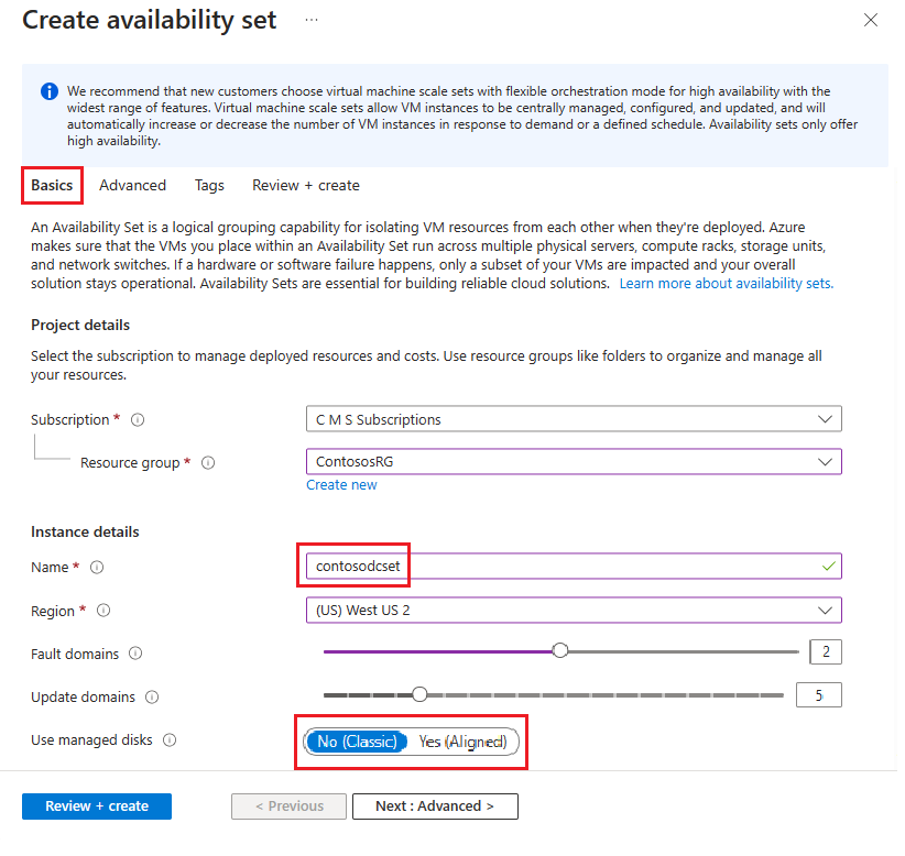
After you're done, select Review + create, then Create.
Repeat the previous steps to create a second availability set with the name contososac2.
Deploy virtual machines
The next step is to deploy VMs that host the different roles in your infrastructure. We recommend a minimum of two machines in each availability set. For this example, we create four VMs for the basic deployment.
To create VMs:
Search for and select Virtual machines in the Azure portal.
On the Virtual machines page, select + Create, then choose Azure virtual machine.
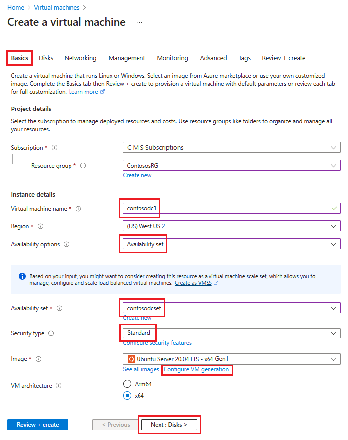
In Create a virtual machine, go to the Basics tab and enter the following information:
Under Project details:
For Subscription, select the name of your subscription.
For Resource group, either select an existing resource group or Create new to make a new one.
Under Instance details:
For Virtual machine name, enter a name for your VM. For the first machine in this example, enter contosodc1.
For Region, select the region you want to use.
For Availability options, select Availability set.
For Availability set, select contosodcset
For Security type, select Standard.
For Subscription, select the name of your subscription.
For Image, select the image you want to use, then select Configure VM generation and select Gen 1.
Under Administrator account:
For Authentication type, select SSH public key.
For Username, enter a user name to use for the account.
For Key pair name, enter a key pair name to use for the account.
For anything not specified, you can leave the default values.
When you're finished, select Next: Disks.
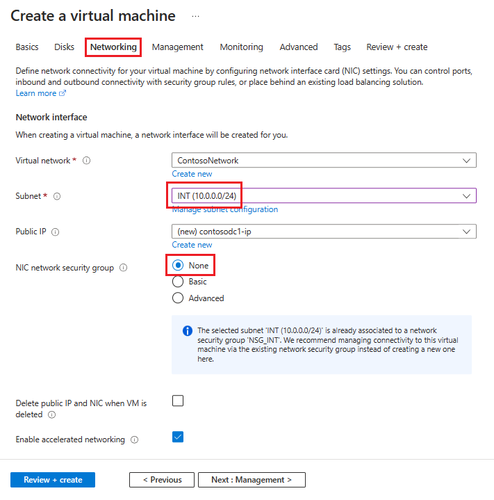
In the Networking tab, enter the following information:
For virtual network, select the name of the virtual network that contains the subnets you created in the previous section.
For Subnet, select your INT subnet.
For NIC network security group, select None.
For anything not specified, you can leave the defaults.
After you've made all your choices, select Review + create, then select Create.
Repeat these steps using the information in this table to create the three remaining VMs:
| Virtual machine name | Subnet | Availability options | Availability set | Storage account |
|---|---|---|---|---|
| contosodc2 | INT | Availability set | contosodcset | contososac2 |
| contosowap1 | DMZ | Availability set | contosowapset | contososac1 |
| contosowap2 | DMZ | Availability set | contosowapset | contososac2 |
The settings don't specify NSG because Azure lets you use NSG at the subnet level. You can control machine network traffic by using the individual NSG associated with either the subnet or the network interface card (NIC) object. For more information, see What is a network security group (NSG).
If you're managing the DNS, we recommend you use a static IP address. You can use Azure DNS and refer to the new machines by their Azure FQDNs in the DNS records for your domain. For more information, see Change a private IP address to static.
Your Virtual machines page should show all four VMs after the deployment completes.
Configure the DC and AD FS servers
To authenticate any incoming request, AD FS needs to contact the DC. To save the costly trip from Azure to on-premises DC for authentication, we recommend you deploy a replica of the DC in Azure. In order to attain high availability, it's better to create an availability set of at least two DCs.
| Domain controller | Role | Storage account |
|---|---|---|
| contosodc1 | Replica | contososac1 |
| contosodc2 | Replica | contososac2 |
We recommend you do the following things:
Promote the two servers as replica DCs with DNS
Configure the AD FS servers by installing the AD FS role using the server manager.
Create and deploy the internal load balancer (ILB)
To create and deploy an ILB:
Search for and select Load Balancers in the Azure portal and choose + Create.
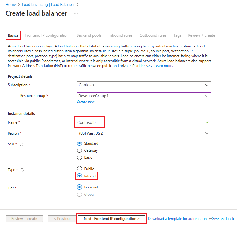
In Create load balancer, enter or select this information in the Basics tab:
Under Project details:
For Subscription, select the name of your subscription.
For Resource group, either select an existing resource group or Create new to make a new one.
Under Instance details:
For Name, enter the name of your load balancer.
For Region, select the region you want to use.
For Type, select Internal.
Leave SKU and Tier as their defaults and then select Next: Frontend IP Configuration
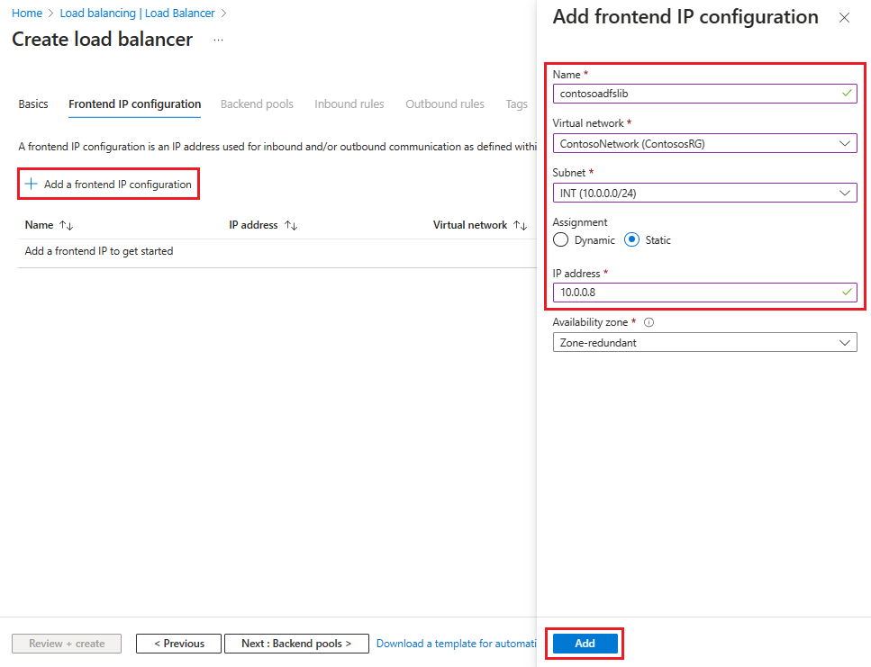
Select + Add a frontend IP configuration, then enter or select this information in the Add frontend IP configuration page.
For Name, enter a frontend IP configuration name.
For Virtual network, select the virtual network where you want to deploy your AD FS.
For Subnet, select INT, which was the internal subnet you created in the previous section.
For Assignment, select Static.
For IP address, enter your IP address.
Leave Availability zone as the default and then select Add.
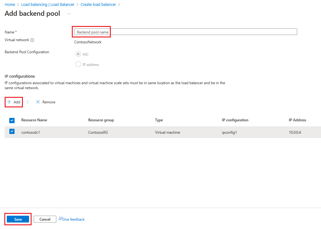
Select Next: Backend pools, then select + Add a backend pool.
On the Add backend pool page, enter a name for the backend pool into the Name field. In the IP configurations area, select + Add.
On the Add backend pool page, select a VM to align with the backend pool, select Add, then select Save.
Select Next: Inbound Rules.
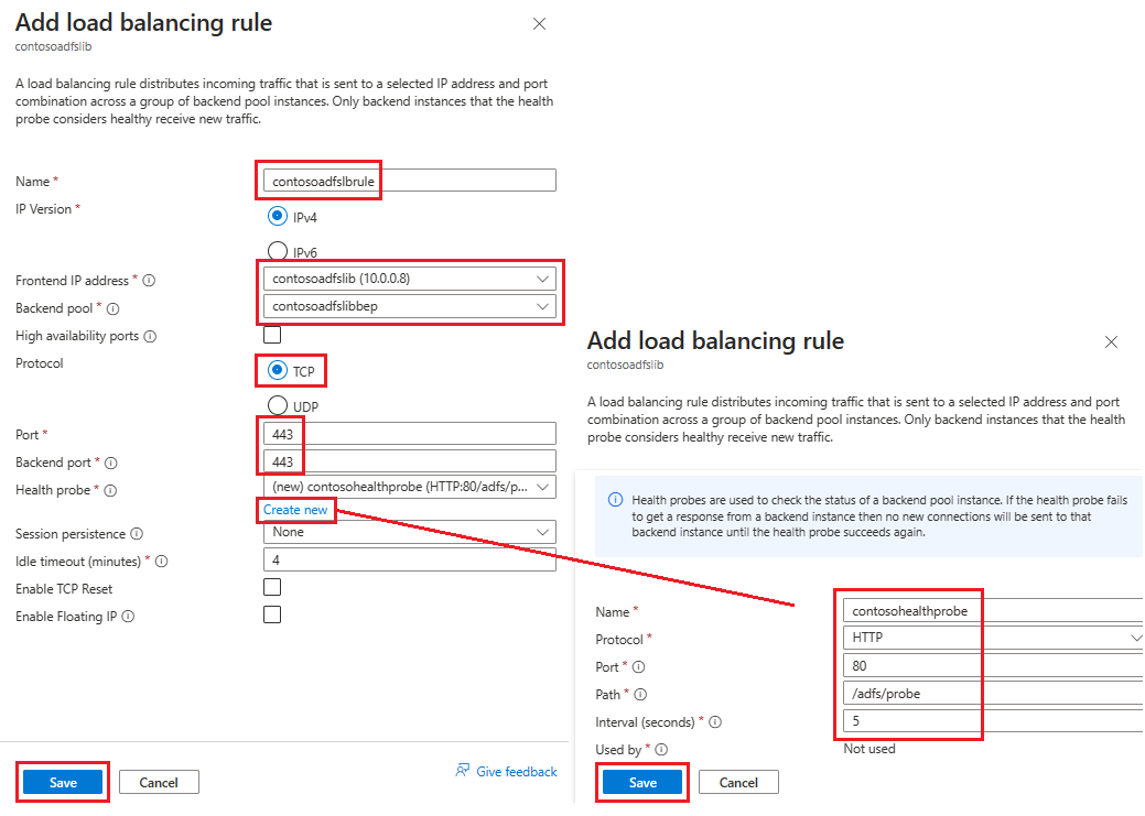
On the Inbound rules tab, select Add a load balancing rule, then enter the following information in the Add load balancing rule page:
For Name, enter a name for the rule.
For Frontend IP address, select the address you created earlier.
For Backend pool, select the backend pool you created earlier.
For Protocol, select TCP.
For Port, enter 443.
For Backend port, select Create new, then enter the following values to create a health probe:
For Name, enter the name of the health probe.
For Protocol, enter HTTP.
For Port, enter 80.
For Path, enter /adfs/probe.
For Interval, leave it at the default value of 5.
When you're finished, select Save.
When you're done, select Save to save the inbound rule.
Select Save to save the inbound rule.
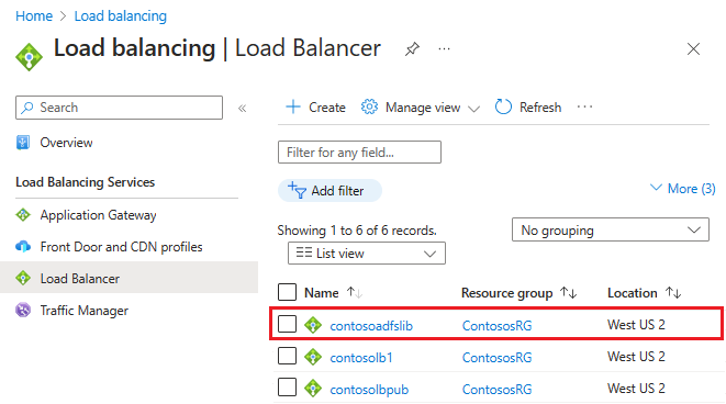
Select Review + create, then select Create.
After you select Create and the ILB deploys, you can see it in the list of load balancers, as shown in the following screenshot.
Update the DNS server with ILB
Using your internal DNS server, create an A record for the ILB. This setting ensures that all data transmitted to fs.contoso.com ends up at the ILB using the appropriate route. The A record should be for the federation service with the IP address pointing to the IP address of the ILB. For example, if the ILB IP address is 10.3.0.8 and the federation service installed is fs.contoso.com, create an A record for fs.contoso.com pointing to 10.3.0.8.
Warning
If you're using the Windows Internal Database (WID) for your AD FS database, set this value to temporarily point to your primary AD FS server. If you don't make this temporary setting change, the web application proxy fails enrollment. After you successfully enroll all web application proxy servers, change this DNS entry to point to the load balancer.
Note
If your deployment is also using IPv6, create a corresponding AAAA record.
Configure the web application proxy servers to reach AD FS servers
To ensure that web application proxy servers are able to reach the AD FS servers behind the ILB, create a record in the %systemroot%\system32\drivers\etc\hosts file for the ILB. The distinguished name (DN) should be the federation service name, such as fs.contoso.com. And the IP entry should be the ILB's IP address, which in this example is 10.3.0.8.
Warning
If you're using the Windows Internal Database (WID) for your AD FS database, set this value to temporarily point to your primary AD FS server. If you don't, the web application proxy fails enrollment. After you successfully enroll all web application proxy servers, change this DNS entry to point to the load balancer.
Install the web application proxy role
After you ensure that web application proxy servers are able to reach the AD FS servers behind ILB, you can next install the web application proxy servers. Web application proxy servers don't need to be joined to the domain. Install the web application proxy roles on the two web application proxy servers by selecting the Remote Access role. The server manager guides you to complete the WAP installation.
For more information on how to deploy WAP, see Install and Configure the web application proxy Server.
Create and deploy the internet-facing (public) load balancer
To create and deploy the internet-facing load balancer:
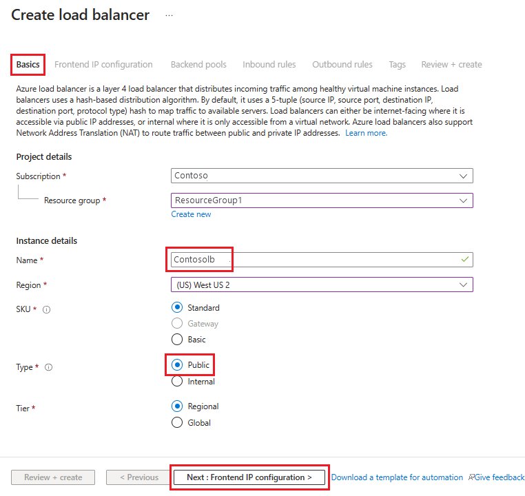
In the Azure portal, select Load balancers and then choose Create.
In Create load balancer, go to the Basics tab and configure the following settings:
Under Project details:
For Subscription, select the name of your subscription.
For Resource group, either select an existing resource group or Create new to make a new one.
Under Instance details:
For Name, enter the name of your load balancer.
For Region, select the region you want to use.
For Type, select Public.
Leave SKU and Tier as their defaults and then select Next : Frontend IP Configuration
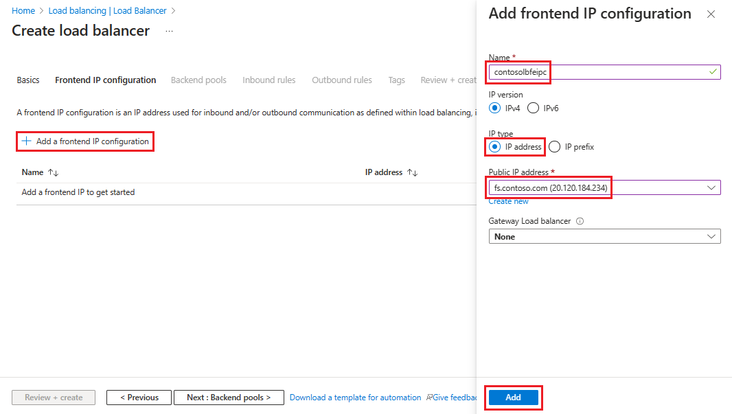
Select + Add a frontend IP configuration, then enter or select this information in the Add frontend IP configuration page.
For Name, enter a frontend IP configuration name.
For IP type, select IP address.
For Public IP Address, either select the public IP address you want to use from the drop-down list or select Create to make a new one, then select Add.
Select Next: Backend pools, then select + Add a backend pool.
On the Add backend pool page, enter a name for the backend pool into the Name field. In the IP configurations area, select + Add.
On the Add backend pool page, select a VM to align with the backend pool, select Add, then select Save.
Select Next: Inbound Rules, then select Add a load balancing rule. In the Add load balancing rule page, configure the following settings:
For Name, enter a name for the rule.
For Frontend IP address, select the address you created earlier.
For Backend pool, select the backend pool you created earlier.
For Protocol, select TCP.
For Port, enter 443.
For Backend port, enter 443.
For Health probe, enter the following values:
For Name, enter the name of the health probe.
For Protocol, enter HTTP.
For Port, enter 80.
For Path, enter /adfs/probe.
For Interval, leave it at the default value of 5.
When you're finished, select Save.
When you're done, select Save to save the inbound rule.
Select Review + create, then select Create.
After you select Create and the public ILB deploys, it should contain a list of load balancers.
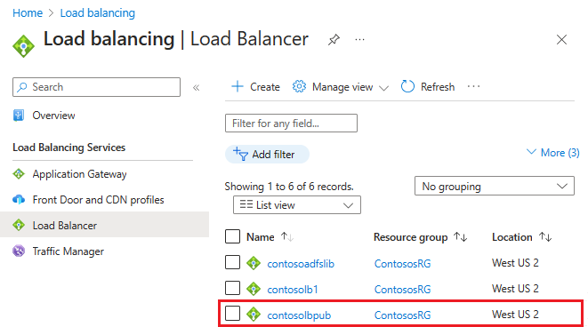
Assign a DNS label to the public IP
To configure the DNS label for the public IP:
In the Azure portal, search for Public IP addresses, then select the IP address you want to edit.
Under Settings, select Configuration.
Under Provide a DNS label (optional), add an entry in the text field (like fs.contoso.com) that resolves to the DNS label of the external load balancer (like contosofs.westus.cloudapp.azure.com).
Select Save to complete assigning a DNS label.
Test the AD FS sign-in
The easiest way to test AD FS is by using the IdpInitiatedSignOn.aspx page. To do that, you must enable the IdpInitiatedSignOn on the AD FS properties.
To check if you have the IdpInitiatedSignOn property enabled:
In PowerShell, run the following cmdlet on the AD FS server to set it to enabled.
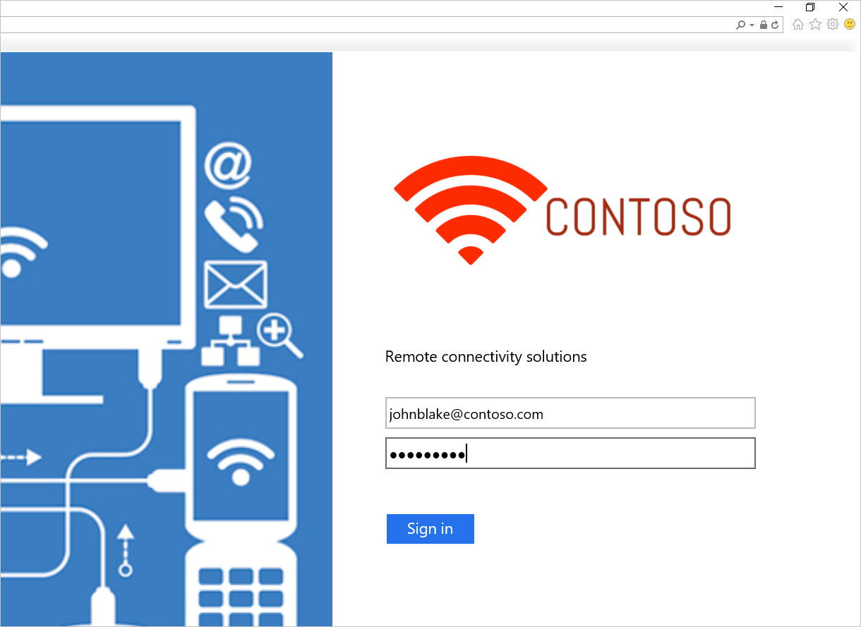
Set-AdfsProperties -EnableIdPInitiatedSignOnPage $trueFrom any external machine, access
https:\//adfs-server.contoso.com/adfs/ls/IdpInitiatedSignon.aspx.You should see the following AD FS page:
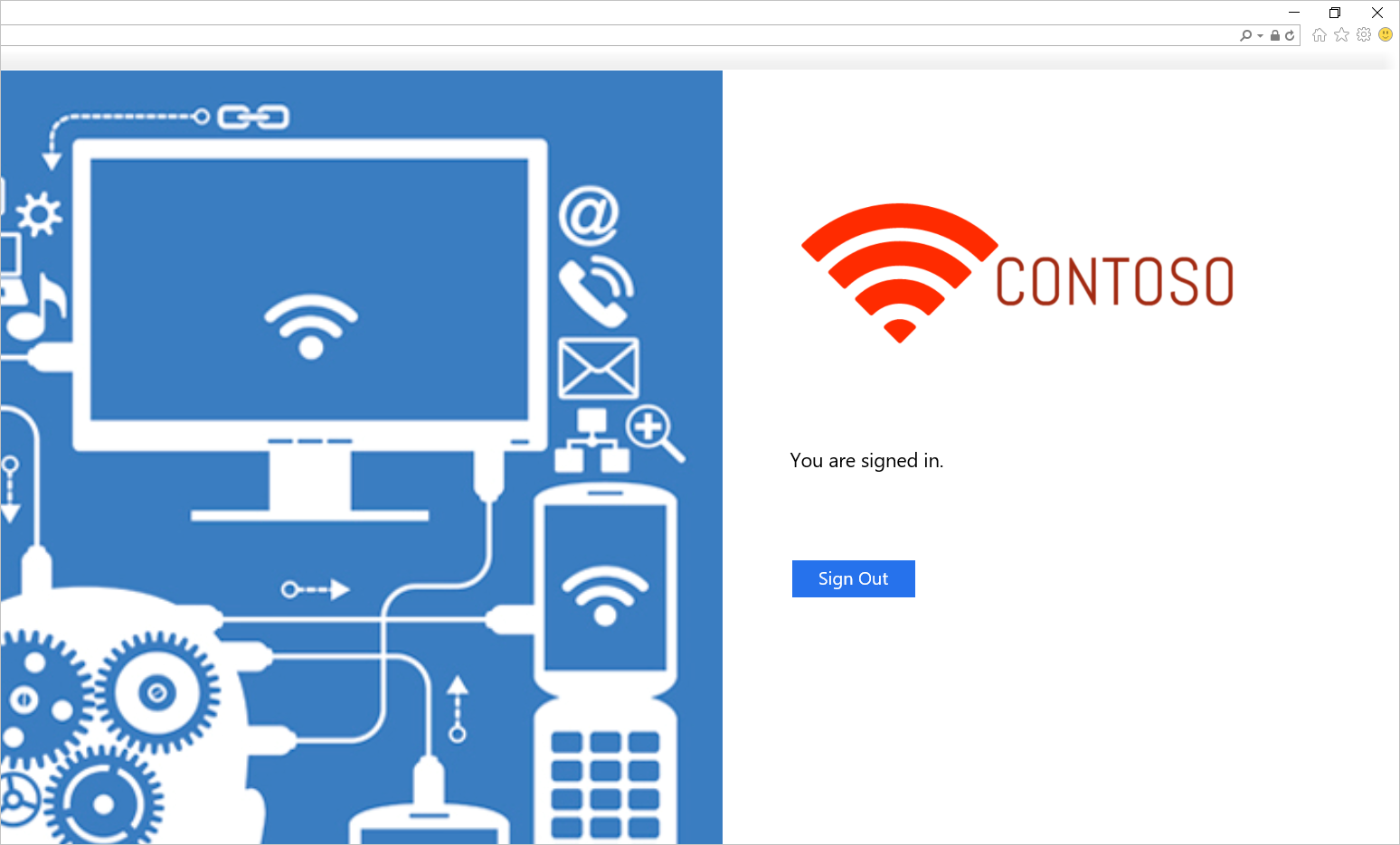
Try to sign in. If you sign in successfully, you should see a message appear, as shown in the following screenshot.
Template for deploying AD FS in Azure
The template deploys a six-machine setup, with two machines each for Domain Controllers, AD FS, and WAP.
AD FS in Azure Deployment Template
You can use an existing virtual network or create a new virtual network while deploying this template. The following table lists the parameters you can use to customize the deployment.
| Parameter | Description |
|---|---|
| Location | The region you want to deploy the resources into. |
| StorageAccountType | The type of the Storage Account you want to create. |
| VirtualNetworkUsage | Indicates whether to create a new virtual network or use an existing one. |
| VirtualNetworkName | The name of the virtual network. Mandatory on both existing or new virtual network usage. |
| VirtualNetworkResourceGroupName | Specifies the name of the resource group where the existing virtual network is located. When you use an existing virtual network, this option is a mandatory parameter so the deployment can find the ID of the existing virtual network. |
| VirtualNetworkAddressRange | The address range of the new virtual network. Mandatory if creating a new virtual network. |
| InternalSubnetName | The name of the internal subnet. Mandatory for both new and existing virtual network usage options. |
| InternalSubnetAddressRange | The address range of the internal subnet, which contains the Domain Controllers and AD FS servers. Mandatory if creating a new virtual network. |
| DMZSubnetAddressRange | The address range of the DMZ subnet, which contains the Windows application proxy servers. Mandatory if creating a new virtual network. |
| DMZSubnetName | The name of the internal subnet, which is mandatory on both new and existing virtual network usage options. |
| ADDC01NICIPAddress | The internal IP address of the first Domain Controller. This IP address is statically assigned to the DC and must be a valid IP address within the Internal subnet. |
| ADDC02NICIPAddress | The internal IP address of the second Domain Controller. This IP address is statically assigned to the DC and must be a valid IP address within the Internal subnet. |
| ADFS01NICIPAddress | The internal IP address of the first AD FS server. This IP address is statically assigned to the AD FS server and must be a valid IP address within the Internal subnet. |
| ADFS02NICIPAddress | The internal IP address of the second AD FS server. This IP address is statically assigned to the AD FS server and must be a valid IP address within the Internal subnet. |
| WAP01NICIPAddress | The internal IP address of the first WAP server. This IP address is statically assigned to the WAP server and must be a valid IP address within the DMZ subnet. |
| WAP02NICIPAddress | The internal IP address of the second WAP server. This IP address is statically assigned to the WAP server and must be a valid IP address within the DMZ subnet. |
| ADFSLoadBalancerPrivateIPAddress | The internal IP address of the AD FS load balancer. This IP address is statically assigned to the load balancer and must be a valid IP address within the Internal subnet. |
| ADDCVMNamePrefix | VM name prefix for Domain Controllers. |
| ADFSVMNamePrefix | VM name prefix for AD FS servers. |
| WAPVMNamePrefix | VM name prefix for WAP servers. |
| ADDCVMSize | The VM size of the Domain Controllers. |
| ADFSVMSize | The VM size of the AD FS servers. |
| WAPVMSize | The VM size of the WAP servers. |
| AdminUserName | The name of the local Administrator of the VMs. |
| AdminPassword | The password for the local Administrator account of the VMs. |
Related links
- Availability sets
- Azure Load Balancer
- Internal Load Balancer
- Internet-facing load balancer
- Storage Accounts
- Azure Virtual Networks
- AD FS and web application proxy Links