Create a hub and spoke topology in Azure - Portal
In this article, you learn how to create a hub and spoke network topology with Azure Virtual Network Manager. With this configuration, you select a virtual network to act as a hub and all spoke virtual networks have bi-directional peering with only the hub by default. You also can enable direct connectivity between spoke virtual networks and enable the spoke virtual networks to use the virtual network gateway in the hub.
Prerequisites
- Read about Hub-and-spoke network topology.
- Created a Azure Virtual Network Manager instance.
- Identify virtual networks you want to use in the hub-and-spokes configuration or create new virtual networks.
Create a network group
This section helps you create a network group containing the virtual networks you're using for the hub-and-spoke network topology.
Note
This how-to guide assumes you created a network manager instance using the quickstart guide.
Browse to the rg-learn-eastus-001 resource group, and select the vnm-learn-eastus-001 network manager instance.
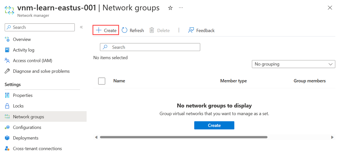
Under Settings, select Network groups. Then select + Create.
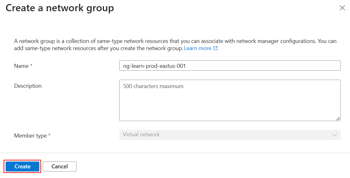
On the Create a network group pane, then select Create:
Setting Value Name Enter ng-learn-prod-eastus-001. Description (Optional) Provide a description about this network group. Member type Select Virtual network from the dropdown menu. and select Create.
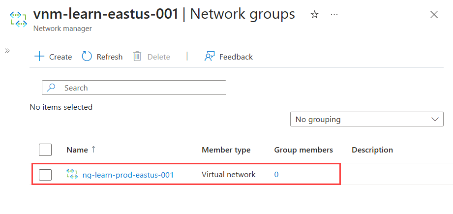
Confirm that the new network group is now listed on the Network groups pane.
Define network group members
Azure Virtual Network manager allows you two methods for adding membership to a network group. You can manually add virtual networks or use Azure Policy to dynamically add virtual networks based on conditions. This how-to covers manually adding membership. For information on defining group membership with Azure Policy, see Define network group membership with Azure Policy.
Manually adding virtual networks
To manually add the desired virtual networks for your Mesh configuration to your Network Group, follow the steps below:
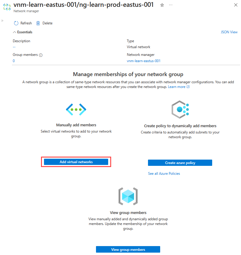
From the list of network groups, select your network group and select Add virtual networks under Manually add members on the network group page.
On the Manually add members page, select all the virtual networks and select Add.
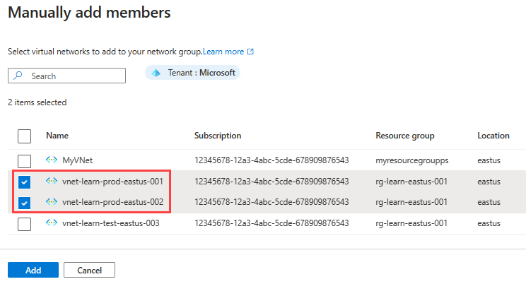
To review the network group membership manually added, select Group Members on the Network Group page under Settings.

Create a hub and spoke connectivity configuration
This section guides you through how to create a hub-and-spoke configuration with the network group you created in the previous section.
Select Connectivity configuration from the drop-down menu to begin creating a connectivity configuration.
On the Basics page, enter the following information, and select Next: Topology >.
Setting Value Name Enter a name for this configuration. Description Optional Enter a description about what this configuration does. On the Topology tab, select the Hub and spoke topology.

Select Delete existing peerings checkbox if you want to remove all previously created virtual network peering between virtual networks in the network group defined in this configuration, and then select Select a hub.
On the Select a hub page, Select a virtual network that acts as the hub virtual network and select Select.

Then select + Add network groups.
On the Add network groups page, select the network groups you want to add to this configuration. Then select Add to save.
The following three options appear next to the network group name under Spoke network groups:

- Direct connectivity: Select Enable peering within network group if you want to establish virtual network peering between virtual networks in the network group of the same region.
- Global Mesh: Select Enable mesh connectivity across regions if you want to establish virtual network peering for all virtual networks in the network group across regions.
- Gateway: Select Use hub as a gateway if you have a virtual network gateway in the hub virtual network that you want this network group to use to pass traffic to on-premises.
Select the settings you want to enable for each network group.
Finally, select Review + Create > Create to create the hub-and-spoke connectivity configuration.
Deploy the hub and spoke configuration
To have this configuration take effect in your environment, you need to deploy the configuration to the regions where your selected virtual networks are created.
Select Deployments under Settings, then select Deploy a configuration.
On the Deploy a configuration page, select the following settings:
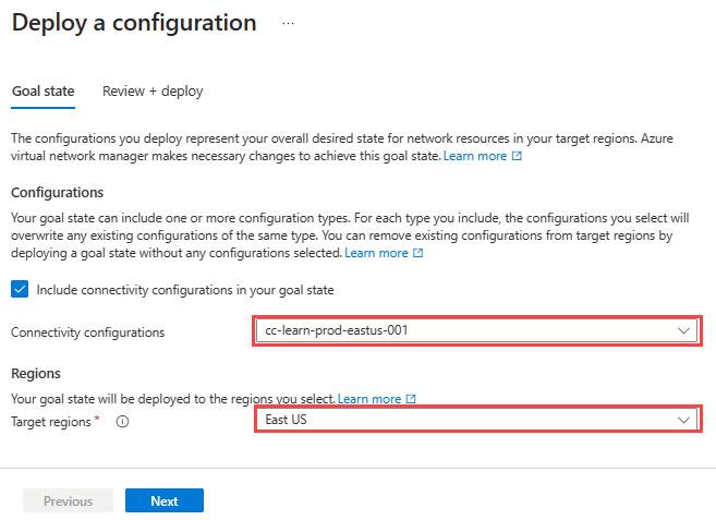
Setting Value Configurations Select Include connectivity configurations in your goal state . Connectivity configurations Select the name of the configuration you created in the previous section. Target regions Select all the regions that apply to virtual networks you select for the configuration. Select Next and then select Deploy to complete the deployment.
The deployment displays in the list for the selected region. The deployment of the configuration can take a few minutes to complete.

Note
If you're currently using peering and want to manage topology and connectivity with Azure Virtual Network Manager, you can migrate without any downtime to your network. Virtual network manager instances are fully compatible with pre-existing hub and spoke topology deployment using peering. This means that you won't need to delete any existing peered connections between the spokes and the hub as the network manager will automatically detect and manage them.
Confirm configuration deployment
To test direct connectivity between spokes, deploy a virtual machine into each spokes virtual network. Then initiate an ICMP request from one virtual machine to the other.
Next steps
- Learn about Security admin rules
- Learn how to block network traffic with a SecurityAdmin configuration.
