Notitie
Voor toegang tot deze pagina is autorisatie vereist. U kunt proberen u aan te melden of de directory te wijzigen.
Voor toegang tot deze pagina is autorisatie vereist. U kunt proberen de mappen te wijzigen.
Active Directory Federation Services (AD FS) biedt vereenvoudigde, beveiligde identiteitsfederatie en mogelijkheden voor eenmalige aanmelding (SSO). Gebruikers die zijn gefedereerd met Microsoft Entra ID of Microsoft 365 kunnen zich verifiëren met behulp van on-premises referenties voor toegang tot alle cloudresources. Als gevolg hiervan moet uw implementatie een maximaal beschikbare AD FS-infrastructuur hebben om toegang tot resources zowel on-premises als in de cloud te garanderen.
Het implementeren van AD FS in Azure kan helpen bij het bereiken van hoge beschikbaarheid zonder te veel inspanning. Er zijn verschillende voordelen van het implementeren van AD FS in Azure:
- De kracht van Azure-beschikbaarheidssets biedt u een maximaal beschikbare infrastructuur.
- Implementaties zijn eenvoudig te schalen. Als u meer prestaties nodig hebt, kunt u eenvoudig migreren naar krachtigere machines met behulp van een vereenvoudigd implementatieproces in Azure.
- Azure-georedundantie zorgt ervoor dat uw infrastructuur wereldwijd maximaal beschikbaar is.
- Azure Portal maakt uw infrastructuur eenvoudiger te beheren met zeer vereenvoudigde beheeropties.
Ontwerpbeginselen
In het volgende diagram ziet u de aanbevolen basistopologie voor het implementeren van de AD FS-infrastructuur in Azure.
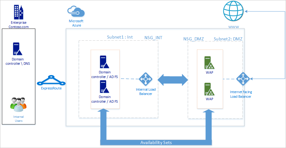
Uw netwerktopologie wordt aangeraden deze algemene principes te volgen:
- Implementeer AD FS op afzonderlijke servers om te voorkomen dat dit van invloed is op de prestaties van uw domeincontrollers.
- U moet WAP-servers (Web Application Proxy) implementeren, zodat gebruikers de AD FS kunnen bereiken wanneer ze zich niet in het bedrijfsnetwerk bevinden.
- U moet de webtoepassingsproxyservers instellen in de gedemilitariseerde zone (DMZ) en alleen TCP/443-toegang toestaan tussen de DMZ en het interne subnet.
- Om hoge beschikbaarheid van AD FS- en webtoepassingsproxyservers te garanderen, raden we u aan een interne load balancer te gebruiken voor AD FS-servers en Azure Load Balancer voor webtoepassingsproxyservers.
- Als u redundantie wilt bieden voor uw AD FS-implementatie, raden we u aan twee of meer virtuele machines (VM's) te groeperen in een beschikbaarheidsset voor vergelijkbare workloads. Deze configuratie zorgt ervoor dat tijdens een geplande of ongeplande onderhoudsgebeurtenis ten minste één VM beschikbaar is.
- U moet webtoepassingsproxyservers implementeren in een afzonderlijk DMZ-netwerk. U kunt één virtueel netwerk verdelen in twee subnetten en vervolgens de proxyservers van de webtoepassing implementeren in een geïsoleerd subnet. U kunt de instellingen voor de netwerkbeveiligingsgroep voor elk subnet configureren en alleen vereiste communicatie tussen de twee subnetten toestaan.
Het netwerk implementeren
Wanneer u een netwerk maakt, kunt u twee subnetten in hetzelfde virtuele netwerk maken of twee verschillende virtuele netwerken maken. We raden u aan de benadering met één netwerk te gebruiken, omdat het maken van twee afzonderlijke virtuele netwerken ook twee afzonderlijke virtuele netwerkgateways vereist voor communicatiedoeleinden.
Een virtueel netwerk maken
Een virtueel netwerk maken:
Meld u met uw Azure-account aan bij Azure Portal.
Zoek en selecteer virtuele netwerken in de portal.
Selecteer + Maken op de pagina Virtuele netwerken.
Ga in Virtueel netwerk maken naar het tabblad Basisbeginselen en configureer de volgende instellingen:
Configureer de volgende instellingen onder Projectdetails:
Selecteer voor Abonnement de naam van uw abonnement.
Voor de resourcegroep selecteert u de naam van een bestaande resourcegroep of selecteert u Nieuwe maken om een nieuwe te maken.
Configureer de volgende instellingen voor exemplaardetails:
Voer een naam in voor de naam van het virtuele netwerk.
Selecteer voor Regio de regio waarin u uw virtuele netwerk wilt maken.
Kies Volgende.
Schakel op het tabblad Beveiliging alle beveiligingsservices in die u wilt gebruiken en selecteer vervolgens Volgende.
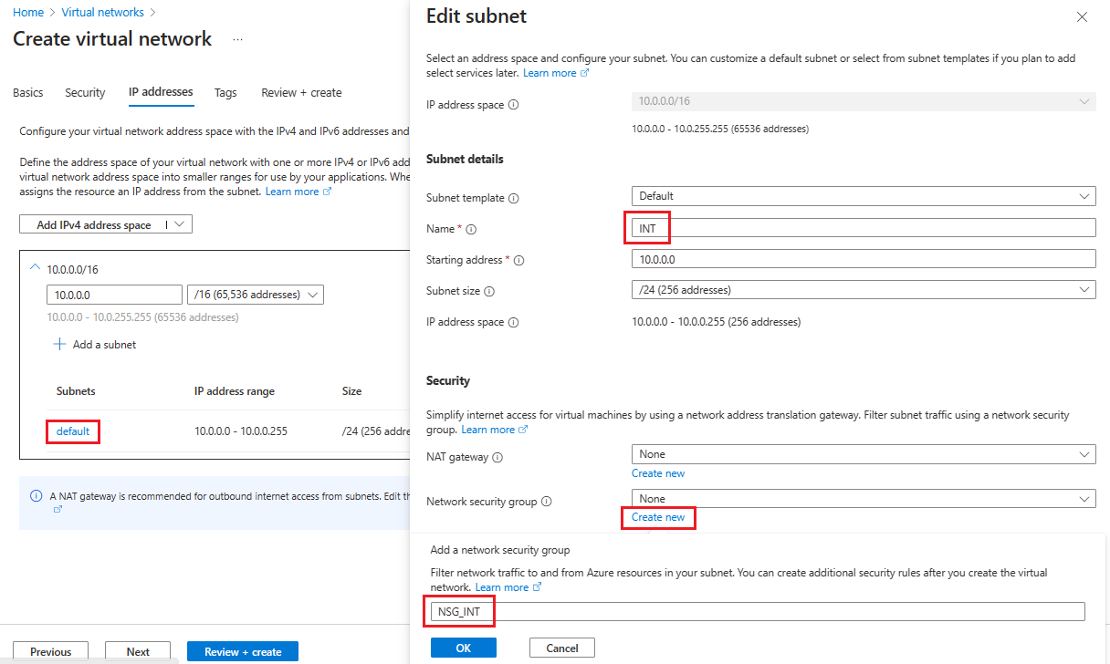
Selecteer op het tabblad IP-adressen de naam van het subnet dat u wilt bewerken. In dit voorbeeld bewerken we het standaardsubnet dat automatisch door de service wordt gemaakt.
Wijzig op de pagina Subnet bewerken de naam van het subnet in INT.
Voer de informatie over de IP-adres - en subnetgrootte voor uw subnet in om een IP-adresruimte te definiëren.
Selecteer Nieuwe maken voor netwerkbeveiligingsgroep.
In dit voorbeeld voert u de naam NSG_INT in en selecteert u OK en selecteert u Vervolgens Opslaan. U hebt nu uw eerste subnet.
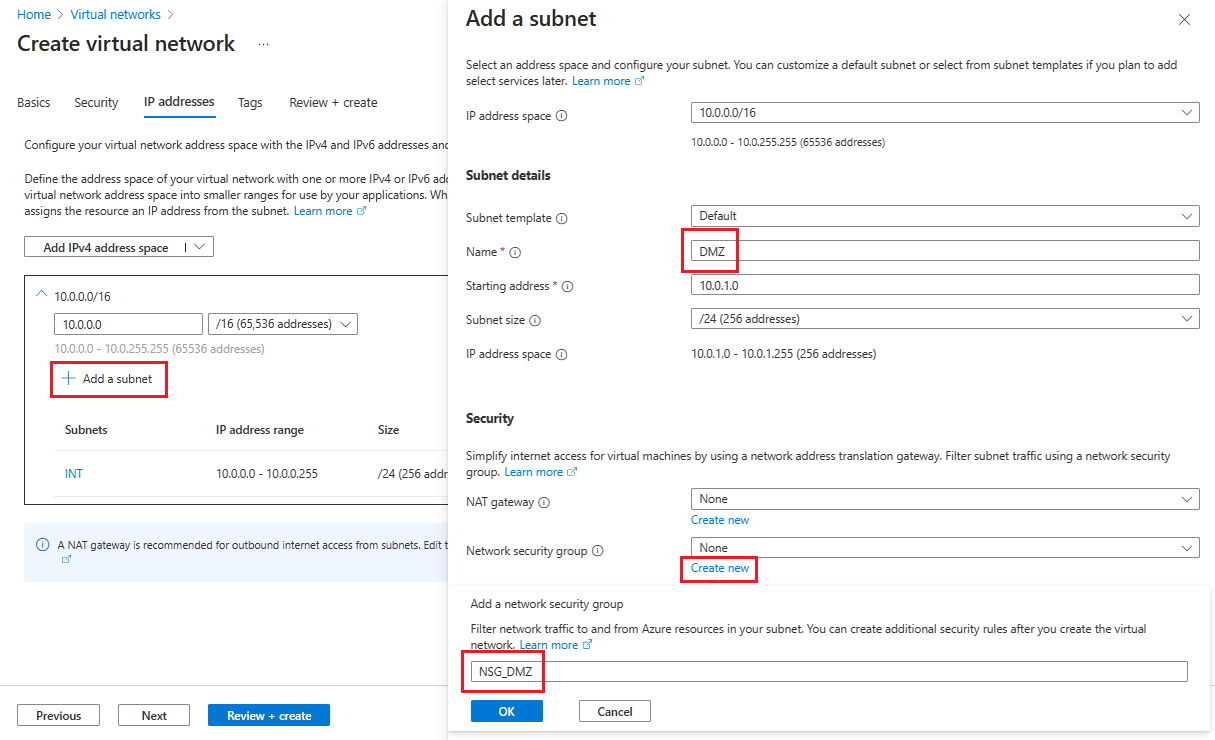
Als u uw tweede subnet wilt maken, selecteert u + Een subnet toevoegen.
Voer op de pagina Een subnet toevoegenDMZ in voor de tweede subnetnaam en voer vervolgens informatie over uw subnet in de lege velden in om een IP-adresruimte te definiëren.
Selecteer Nieuwe maken voor netwerkbeveiligingsgroep.
Voer de naam NSG_DMZ in, selecteer OK en selecteer Vervolgens Toevoegen.
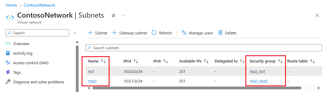
Selecteer Beoordelen + creëren en selecteer daarna Creëren.
U hebt nu een virtueel netwerk met twee subnetten, elk met een gekoppelde netwerkbeveiligingsgroep.
Het virtuele netwerk beveiligen
Een netwerkbeveiligingsgroep (NSG) bevat een lijst met ACL-regels (Access Control List) waarmee netwerkverkeer naar uw VM-exemplaren in een virtueel netwerk wordt toegestaan of geweigerd. U kunt NSG's koppelen aan subnetten of afzonderlijke VM-exemplaren binnen dat subnet. Als een NSG is gekoppeld aan een subnet, zijn de ACL-regels van toepassing op alle VM-exemplaren in dat subnet.
De NSG's die aan uw subnetten zijn gekoppeld, bevatten automatisch enkele standaardregels voor inkomend en uitgaand verkeer. U kunt standaardbeveiligingsregels niet verwijderen, maar u kunt ze overschrijven met regels met een hogere prioriteit. En u kunt meer regels voor inkomend en uitgaand verkeer toevoegen op basis van het gewenste beveiligingsniveau.
Voeg nu een aantal regels toe aan elk van onze twee beveiligingsgroepen. In het eerste voorbeeld gaan we een beveiligingsregel voor binnenkomend verkeer toevoegen aan de NSG_INT beveiligingsgroep.
Selecteer NSG_INT op de pagina Subnetten van uw virtuele netwerk.
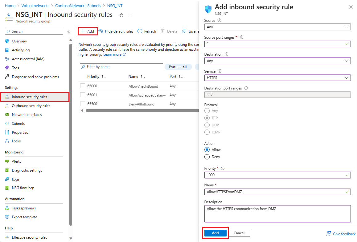
Selecteer aan de linkerkant inkomende beveiligingsregels en selecteer vervolgens + Toevoegen.
Configureer in Binnenkomende beveiligingsregel toevoegen de regel met de volgende informatie:
Voor Bron voert u 10.0.1.0/24 in.
Voor de bronpoortbereiken laat u deze leeg als u geen verkeer wilt toestaan of een sterretje (*) wilt selecteren om verkeer op een willekeurige poort toe te staan.
Voer voor Bestemming10.0.0.0/24 in.
Selecteer HTTPS voor de service. De service vult automatisch de informatievelden voor doelpoortbereiken en Protocol in, afhankelijk van de service die u kiest.
Bij Actie selecteert u Toestaan.
Voer voor Prioriteit1010 in.
Voer voor NaamAllowHTTPSFromDMZ in.
Voer voor Beschrijvingde HTTPS-communicatie van DMZ toestaan in.
Nadat u klaar bent, selecteert u Toevoegen.
 De nieuwe beveiligingsregel voor inkomend verkeer wordt nu toegevoegd aan de bovenkant van de lijst met regels voor NSG_INT.
Herhaal deze stappen met de waarden die worden weergegeven in de volgende tabel. Naast de nieuwe regel die u hebt gemaakt, moet u de volgende extra regels toevoegen in de prioriteitsvolgorde die wordt vermeld om uw interne en DMZ-subnet te beveiligen.
NSG Type regel Bron Bestemming Dienst Handeling Prioriteit Naam Beschrijving NSG_INT Uitgaand Welke dan ook Service tag en internet Aangepast (80/Ieder) Weigeren 100 DenyInternetOutbound Geen toegang tot internet. NSG_DMZ Inkomend Welke dan ook Welke dan ook Aangepast (sterretje (*)/Elke) Toestaan 1010 AllowHTTPSFromInternet HTTPS van internet naar de DMZ toestaan. NSG_DMZ Uitgaand Welke dan ook Servicetag/Internet Aangepast (80/Any) Weigeren 100 DenyInternetOutbound Alles behalve HTTPS naar internet wordt geblokkeerd. Nadat u de waarden voor elke nieuwe regel hebt ingevoerd, selecteert u Toevoegen en gaat u verder met de volgende totdat er voor elke NSG twee nieuwe beveiligingsregels worden toegevoegd.
Na de configuratie moeten de NSG-pagina's er als volgt uitzien:

Opmerking
Als voor het virtuele netwerk verificatie van clientgebruikerscertificaten is vereist, zoals clientTLS-verificatie met X.509-gebruikerscertificaten, moet u TCP-poort 49443 inschakelen voor binnenkomende toegang.
Verbinding maken met on-premises
U hebt een verbinding met on-premises nodig om de DC in Azure te implementeren. U kunt uw on-premises infrastructuur verbinden met uw Azure-infrastructuur met behulp van een van de volgende opties:
- Punt-naar-site
- Site-naar-site van virtueel netwerk
- ExpressRoute
U wordt aangeraden ExpressRoute te gebruiken als uw organisatie geen punt-naar-site- of virtual network-site-naar-site-verbindingen nodig heeft. Met ExpressRoute kunt u privéverbindingen maken tussen Azure-datacenters en infrastructuur die zich on-premises of in een colocatieomgeving bevindt. ExpressRoute-verbindingen maken ook geen verbinding met het openbare internet, waardoor ze betrouwbaarder, sneller en veiliger zijn. Lees het technische overzicht van ExpressRoute voor meer informatie over ExpressRoute en de verschillende connectiviteitsopties met behulp van ExpressRoute.
Beschikbaarheidssets maken
Maak voor elke rol (DC/AD FS en WAP) beschikbaarheidssets die elk ten minste twee computers bevatten. Deze configuratie helpt bij het bereiken van een hogere beschikbaarheid voor elke rol. Tijdens het maken van de beschikbaarheidssets moet u bepalen welke van de volgende domeinen u wilt gebruiken:
In een foutdomein delen VM's dezelfde voedingsbron en fysieke netwerkswitch. We raden minimaal twee foutdomeinen aan. De standaardwaarde is 2 en u kunt deze as-is laten voor deze implementatie.
In een updatedomein worden computers opnieuw opgestart tijdens een update. We raden minimaal twee updatedomeinen aan. De standaardwaarde is 5 en u kunt deze as-is laten voor deze implementatie.
Beschikbaarheidssets maken:
Zoek naar en selecteer Availability sets in het Azure-portaal en klik op + Maken.
Ga in de beschikbaarheidsset maken naar het tabblad Basisinformatie en voer de volgende informatie in:
Onder Projectdetails:
Selecteer voor Abonnement de naam van uw abonnement.
Selecteer voor de resourcegroep een bestaande resourcegroep of maak een nieuwe om een nieuwe te maken.
Geef onder Exemplaardetails het volgende op:
Voer bij Naam de naam in voor uw beschikbaarheidsset. Voer voor dit voorbeeld contosodcset in.
Selecteer voor Regio de regio die u wilt gebruiken.
Laat voor foutdomeinen de standaardwaarde 2 staan.
Laat voor Update-domeinen de standaardwaarde 5 staan.
Voor Beheerde schijven gebruiken selecteert u Nee (klassiek) voor dit voorbeeld.
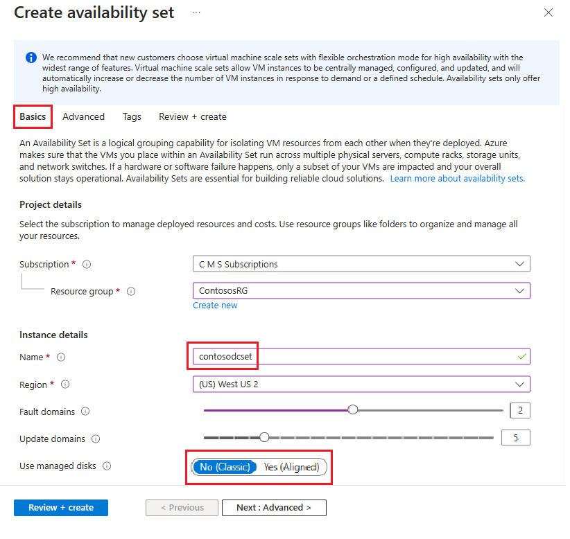
Nadat u klaar bent, selecteert u Beoordelen en maken en vervolgens Maken.
Herhaal de vorige stappen om een tweede beschikbaarheidsset te maken met de naam contososac2.
Virtuele machines implementeren
De volgende stap bestaat uit het implementeren van VM's die als host fungeren voor de verschillende rollen in uw infrastructuur. U wordt aangeraden minimaal twee machines in elke beschikbaarheidsset te gebruiken. In dit voorbeeld maken we vier VM's voor de basisimplementatie.
Vm's maken:
Zoek en selecteer virtuele machines in Azure Portal.
Selecteer + Maken op de pagina Virtuele machines en kies vervolgens virtuele Azure-machine.
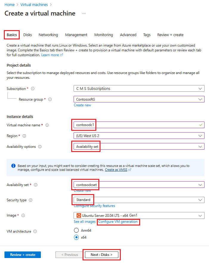
Ga in Een virtuele machine maken naar het tabblad Basisbeginselen en voer de volgende gegevens in:
Onder Projectdetails:
Selecteer voor Abonnement de naam van uw abonnement.
Selecteer voor de resourcegroep een bestaande resourcegroep of maak een nieuwe om een nieuwe te maken.
Geef onder Exemplaardetails het volgende op:
Voer een naam in voor de naam van de virtuele machine. Voer contosodc1 in voor de eerste computer in dit voorbeeld.
Selecteer voor Regio de regio die u wilt gebruiken.
Selecteer Beschikbaarheidsset voor beschikbaarheidsopties.
Selecteer contosodcset voor de beschikbaarheidsset
Selecteer Standard als beveiligingstype.
Selecteer voor Abonnement de naam van uw abonnement.
Selecteer voor Installatiekopieën de installatiekopieën die u wilt gebruiken, selecteer vervolgens Generatie van VM configureren en selecteer Gen 1.
Onder Administrator-account:
Bij Verificatietype selecteert u Openbare SSH-sleutel.
Voer voor gebruikersnaam een gebruikersnaam in die u voor het account wilt gebruiken.
Voer voor de naam van het sleutelpaar een sleutelpaarnaam in die u voor het account wilt gebruiken.
Voor niets dat niet is opgegeven, kunt u de standaardwaarden behouden.
Wanneer u klaar bent, selecteert u Volgende: Schijven.
Voer op het tabblad Netwerken de volgende gegevens in:
Selecteer voor het virtuele netwerk de naam van het virtuele netwerk met de subnetten die u in de vorige sectie hebt gemaakt.
Voor Subnet selecteer uw INT-subnet.
Selecteer Geen voor NIC-netwerkbeveiligingsgroep.
Voor niets dat niet is opgegeven, kunt u de standaardwaarden laten staan.
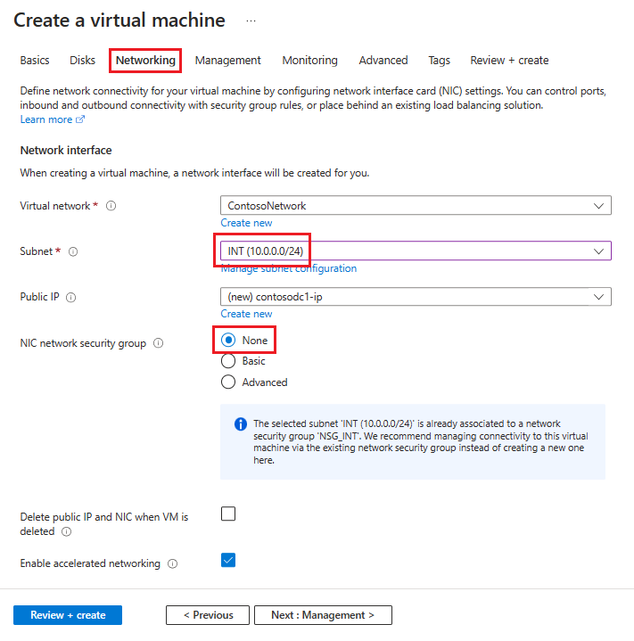
Nadat u al uw keuzes hebt gemaakt, selecteert u Beoordelen en maken en dan Maken.
Herhaal deze stappen met behulp van de informatie in deze tabel om de drie resterende VM's te maken:
| Naam van de virtuele machine | Subnetwerk | Beschikbaarheidsopties | Beschikbaarheidsconfiguratie | Opslagaccount |
|---|---|---|---|---|
| contosodc2 | INT | Beschikbaarheidsconfiguratie | contosodcset | contososac2 |
| contosowap1 | Gedemilitariseerde Zone (DMZ) | Beschikbaarheidsconfiguratie | contosowapset | contososac1 |
| contosowap2 | DMZ (gedemilitariseerde zone) | Beschikbaarheidsconfiguratie | contosowapset | contososac2 |
De instellingen geven geen NSG op, omdat u met Azure NSG op subnetniveau kunt gebruiken. U kunt het netwerkverkeer van de machine beheren met behulp van de afzonderlijke NSG die is gekoppeld aan het subnet of het NIC-object (Network Interface Card). Zie Wat is een netwerkbeveiligingsgroep (NSG) voor meer informatie.
Als u de DNS beheert, raden we u aan een statisch IP-adres te gebruiken. U kunt Azure DNS gebruiken en verwijzen naar de nieuwe machines door hun Azure FQDN's in de DNS-records voor uw domein. Zie Een privé-IP-adres wijzigen in statisch voor meer informatie.
Op de pagina Virtuele machines moeten alle vier de VM's worden weergegeven nadat de implementatie is voltooid.
De DC- en AD FS-servers configureren
Als u een binnenkomende aanvraag wilt verifiëren, moet AD FS contact opnemen met de DC. Als u de kostbare reis van Azure naar on-premises DC wilt besparen voor verificatie, raden we u aan om een replica van de DC in Azure te implementeren. Om hoge beschikbaarheid te verkrijgen, is het aan te raden een beschikbaarheidsset van ten minste twee DC's te maken.
| Domeincontroller | Rol | Opslagaccount |
|---|---|---|
| contosodc1 | Reproductie | contososac1 |
| contosodc2 | Reproductie | contososac2 |
U wordt aangeraden de volgende handelingen uit te voeren:
Promoveer de twee servers als replica-DC's met DNS
Configureer de AD FS-servers door de AD FS-functie te installeren met serverbeheer.
De interne load balancer (ILB) maken en implementeren
Een ILB maken en implementeren:
Zoek en selecteer Load Balancers in Azure Portal en kies + Maken.
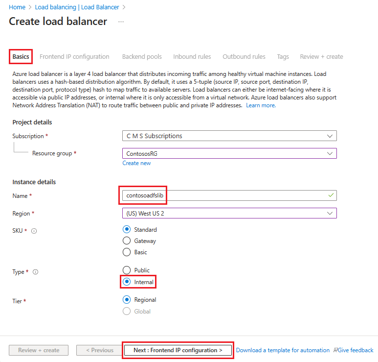
Voer in Load Balancer maken deze informatie in of selecteer deze op het tabblad Basisbeginselen :
Onder Projectdetails:
Selecteer voor Abonnement de naam van uw abonnement.
Selecteer voor de resourcegroep een bestaande resourcegroep of maak een nieuwe om een nieuwe te maken.
Geef onder Exemplaardetails het volgende op:
Voer bij Naam de naam van uw load balancer in.
Selecteer voor Regio de regio die u wilt gebruiken.
Voor Type selecteert u Intern.
Laat SKU en Tier op de standaardwaarden staan en selecteer vervolgens Volgende: Frontend-IP-configuratie
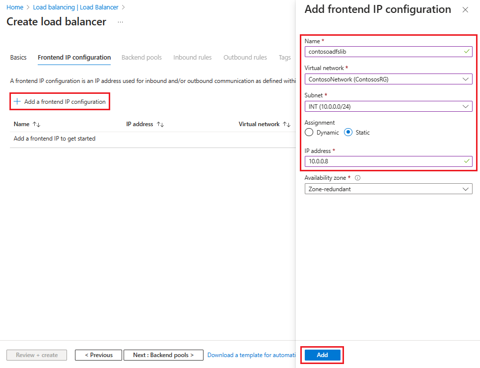
Selecteer + Een front-end-IP-configuratie toevoegen en voer deze gegevens in of selecteer deze op de pagina Ip-configuratie van front-end toevoegen .
Voer bij Naam een front-end-IP-configuratienaam in.
Voor virtueel netwerk selecteert u het virtuele netwerk waar u uw AD FS wilt implementeren.
Voor Subnet selecteert u INT, het interne subnet dat u in de vorige sectie hebt gemaakt.
Selecteer Statisch voor Toewijzing.
Voer uw IP-adres in.
Laat de beschikbaarheidszone standaard staan en selecteer vervolgens Toevoegen.
Selecteer Volgende: Back-endpools en selecteer vervolgens + Een back-endpool toevoegen.
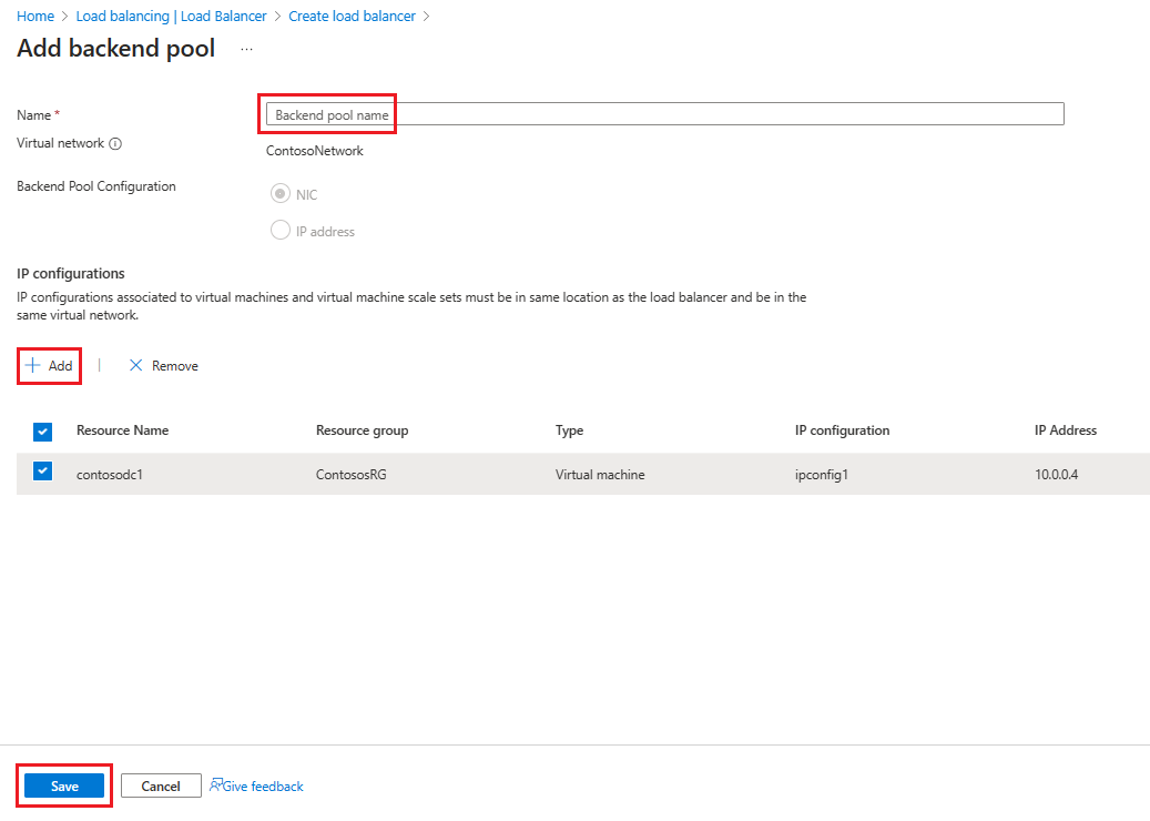
Voer op de pagina Back-endpool toevoegen een naam in voor de back-endpool in het veld Naam . Selecteer + Toevoegen in het gebied IP-configuraties.
Selecteer op de pagina Back-endpool toevoegen een virtuele machine die u wilt uitlijnen met de back-endpool, selecteer Toevoegen en selecteer Vervolgens Opslaan.
Selecteer Volgende: Regels voor inkomend verkeer.
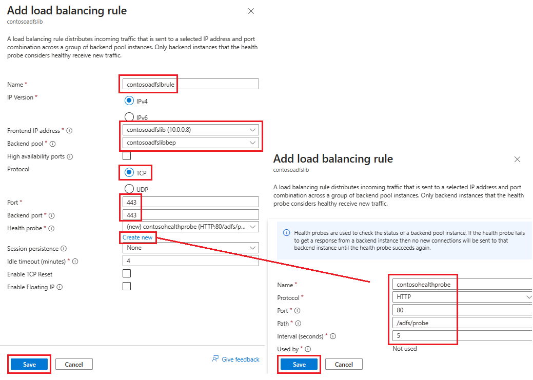
Selecteer op het tabblad Regels voor inkomend verkeereen taakverdelingsregel toevoegen en voer vervolgens de volgende informatie in op de pagina Taakverdelingsregel toevoegen :
Voer bij Naam een naam in voor de regel.
Selecteer voor front-end-IP-adres het adres dat u eerder hebt gemaakt.
Selecteer voor back-endpool de back-endpool die u eerder hebt gemaakt.
Bij Protocol selecteert u TCP.
For Port, enter 443.
Voor de back-endpoort selecteert u Nieuw maken en voert u vervolgens de volgende waarden in om een statustest te maken:
Voer bij Naam de naam van de statustest in.
Voer HTTP in voor Protocol.
Voer voor Poort80 in.
Voer voor Pad/adfs/probe in.
Laat voor Interval de standaardwaarde 5 staan.
Wanneer u klaar bent, selecteert u Opslaan.
Wanneer u klaar bent, selecteert u Opslaan om de regel voor inkomend verkeer op te slaan.
Selecteer Opslaan om de regel voor inkomend verkeer op te slaan.
Selecteer Beoordelen + creëren en selecteer daarna Creëren.
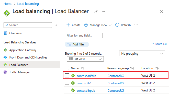
Nadat u Maken hebt geselecteerd en de ILB is geïmplementeerd, kunt u deze zien in de lijst met load balancers, zoals te zien in de volgende schermopname.
De DNS-server bijwerken met ILB
Maak met behulp van uw interne DNS-server een A-record voor de ILB. Deze instelling zorgt ervoor dat alle gegevens die naar fs.contoso.com worden verzonden, terechtkomen bij de ILB via de juiste route. De A-record moet voor de federatiedienst zijn, waarbij het IP-adres verwijst naar het IP-adres van de ILB. Als het IP-adres van de ILB bijvoorbeeld 10.3.0.8 is en de geïnstalleerde federation-service is fs.contoso.com, maakt u een A-record voor fs.contoso.com die 10.3.0.8 aanwijst.
Waarschuwing
Als u de interne Windows-database (WID) voor uw AD FS-database gebruikt, stelt u deze waarde in om tijdelijk naar uw primaire AD FS-server te verwijzen. Als u deze tijdelijke instelling niet wijzigt, mislukt de inschrijving van de webtoepassingsproxy. Nadat u alle webtoepassingsproxyservers hebt ingeschreven, wijzigt u deze DNS-vermelding zodat deze verwijst naar de load balancer.
Opmerking
Als uw implementatie ook IPv6 gebruikt, maakt u een bijbehorende AAAA-record.
Configureer de proxyservers voor webtoepassingen zodat ze AD FS-servers kunnen bereiken.
Om ervoor te zorgen dat webtoepassingsproxyservers de AD FS-servers achter de ILB kunnen bereiken, maakt u een record in de %systemroot%\system32\drivers\etc\hosts-bestand voor de ILB. De DN (DN) moet de naam van de federation-service zijn, zoals fs.contoso.com. En de IP-vermelding moet het IP-adres van de ILB zijn, dat in dit voorbeeld 10.3.0.8 is.
Waarschuwing
Als u de interne Windows-database (WID) voor uw AD FS-database gebruikt, stelt u deze waarde in om tijdelijk naar uw primaire AD FS-server te verwijzen. Als u dit niet doet, mislukt de inschrijving van de webtoepassingsproxy. Nadat u alle webtoepassingsproxyservers hebt ingeschreven, wijzigt u deze DNS-vermelding zodat deze verwijst naar de load balancer.
De webtoepassingsproxyrol installeren
Nadat u ervoor hebt gezorgd dat webtoepassingsproxyservers de AD FS-servers achter ILB kunnen bereiken, kunt u de webtoepassingsproxyservers vervolgens installeren. Webtoepassingsproxyservers hoeven niet aan het domein te worden toegevoegd. Installeer de webtoepassingsproxyrollen op de twee webtoepassingsproxyservers door de rol Externe toegang te selecteren. De serverbeheer begeleidt u bij het voltooien van de WAP-installatie.
Zie De webtoepassingsproxyserver installeren en configureren voor meer informatie over het implementeren van WAP.
De internetgerichte (openbare) load balancer maken en implementeren
Om de internetgerichte load balancer te creëren en implementeren:
Selecteer in de Azure Portal Load balancers en kies Maken.
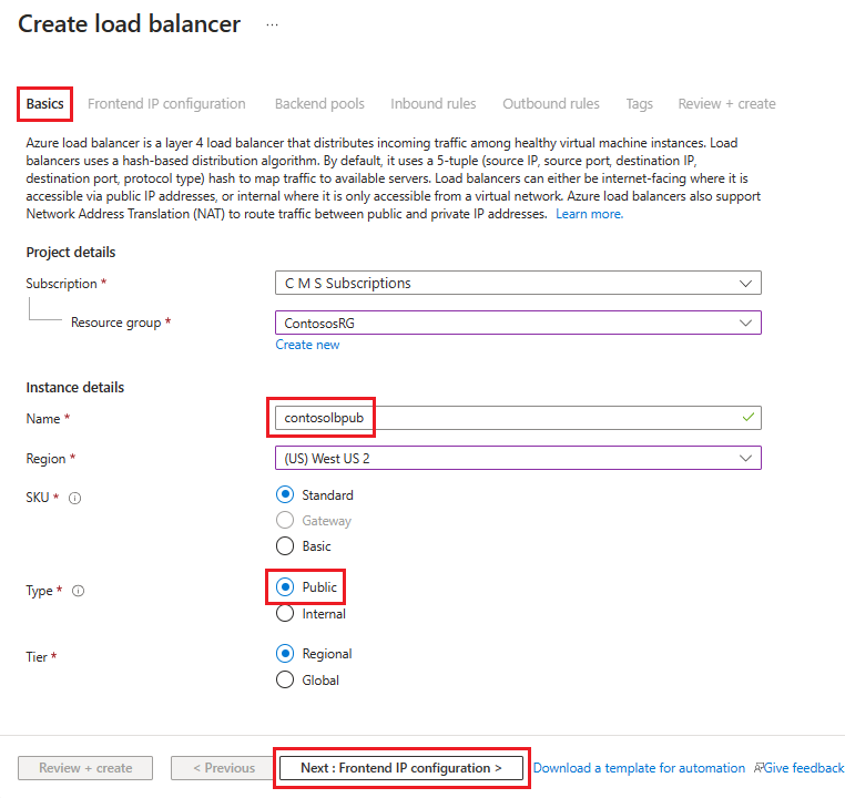
Ga in Load Balancer maken naar het tabblad Basisbeginselen en configureer de volgende instellingen:
Onder Projectdetails:
Selecteer voor Abonnement de naam van uw abonnement.
Selecteer voor de resourcegroep een bestaande resourcegroep of maak een nieuwe om een nieuwe te maken.
Geef onder Exemplaardetails het volgende op:
Voer bij Naam de naam van uw load balancer in.
Selecteer voor Regio de regio die u wilt gebruiken.
Selecteer Voor Typede optie Openbaar.
Laat de SKU en Tier op de standaardwaarden staan en selecteer vervolgens Volgende: Frontend-IP-configuratie
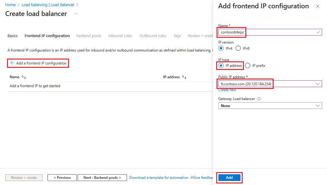
Selecteer + Een front-end-IP-configuratie toevoegen en voer deze gegevens in of selecteer deze op de pagina Ip-configuratie van front-end toevoegen .
Voer bij Naam een front-end-IP-configuratienaam in.
Selecteer IP-adres voor IP-type.
Voor openbaar IP-adres selecteert u het openbare IP-adres dat u wilt gebruiken in de vervolgkeuzelijst of selecteert u Maken om een nieuw IP-adres te maken en selecteert u Vervolgens Toevoegen.
Selecteer Volgende: Back-endpools en selecteer + Een back-endpool toevoegen.
Voer op de pagina Back-endpool toevoegen een naam in voor de back-endpool in het veld Naam . Selecteer + Toevoegen in het gebied IP-configuraties.
Selecteer op de pagina Back-endpool toevoegen een virtuele machine die u wilt uitlijnen met de back-endpool, selecteer Toevoegen en selecteer Vervolgens Opslaan.
Selecteer Volgende: Regels voor inkomend verkeer en selecteer vervolgens Een taakverdelingsregel toevoegen. Configureer op de pagina Taakverdelingsregel toevoegen de volgende instellingen:
Voer bij Naam een naam in voor de regel.
Selecteer voor front-end-IP-adres het adres dat u eerder hebt gemaakt.
Selecteer voor back-endpool de back-endpool die u eerder hebt gemaakt.
Bij Protocol selecteert u TCP.
For Port, enter 443.
Voer 443 in voor de back-endpoort.
Voer voor statustest de volgende waarden in:
Voer bij Naam de naam van de gezondheidsprobe in.
Voer HTTP in voor Protocol.
Voer voor Poort80 in.
Voer voor Pad/adfs/probe in.
Laat voor Interval de standaardwaarde 5 staan.
Wanneer u klaar bent, selecteert u Opslaan.
Wanneer u klaar bent, selecteert u Opslaan om de regel voor inkomend verkeer op te slaan.
Selecteer Beoordelen + creëren en selecteer daarna Creëren.
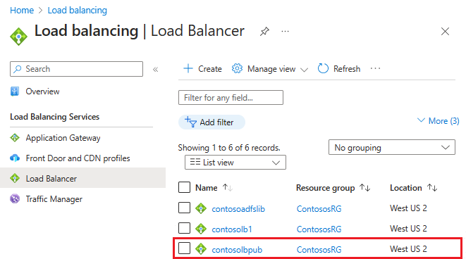
Nadat u Maken en de openbare ILB hebt geïmplementeerd, moet deze een lijst met load balancers bevatten.
Een DNS-label toewijzen aan het openbare IP-adres
Het DNS-label voor het openbare IP-adres configureren:
Zoek in Azure Portal naar openbare IP-adressen en selecteer vervolgens het IP-adres dat u wilt bewerken.
Selecteer onder Instellingen de optie Configuratie.
Voeg onder Een DNS-label opgeven (optioneel) een vermelding toe in het tekstveld (zoals fs.contoso.com) die wordt omgezet in het DNS-label van de externe load balancer (zoals contosofs.westus.cloudapp.azure.com).
Selecteer Opslaan om het toewijzen van een DNS-label te voltooien.
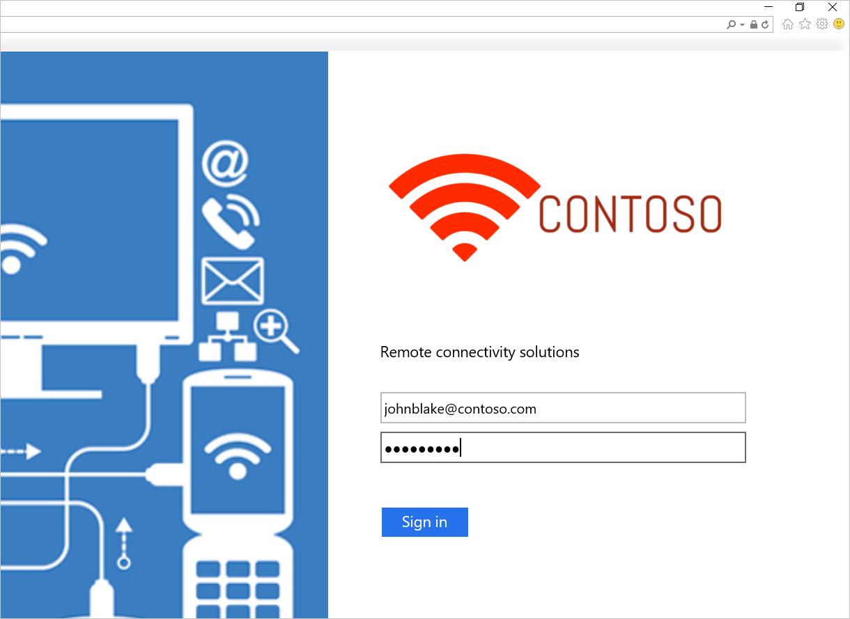
De AD FS-aanmelding testen
De eenvoudigste manier om AD FS te testen is met behulp van de IdpInitiatedSignOn.aspx pagina. Hiervoor moet u de IdpInitiatedSignOn inschakelen op de AD FS-eigenschappen.
Controleren of de eigenschap IdpInitiatedSignOn is ingeschakeld:
Voer in PowerShell de volgende cmdlet uit op de AD FS-server om deze in te stellen op ingeschakeld.
Set-AdfsProperties -EnableIdPInitiatedSignOnPage $trueVanaf elke externe machine kunt u toegang verkrijgen tot
https:\//adfs-server.contoso.com/adfs/ls/IdpInitiatedSignon.aspx.U ziet nu de volgende AD FS-pagina:
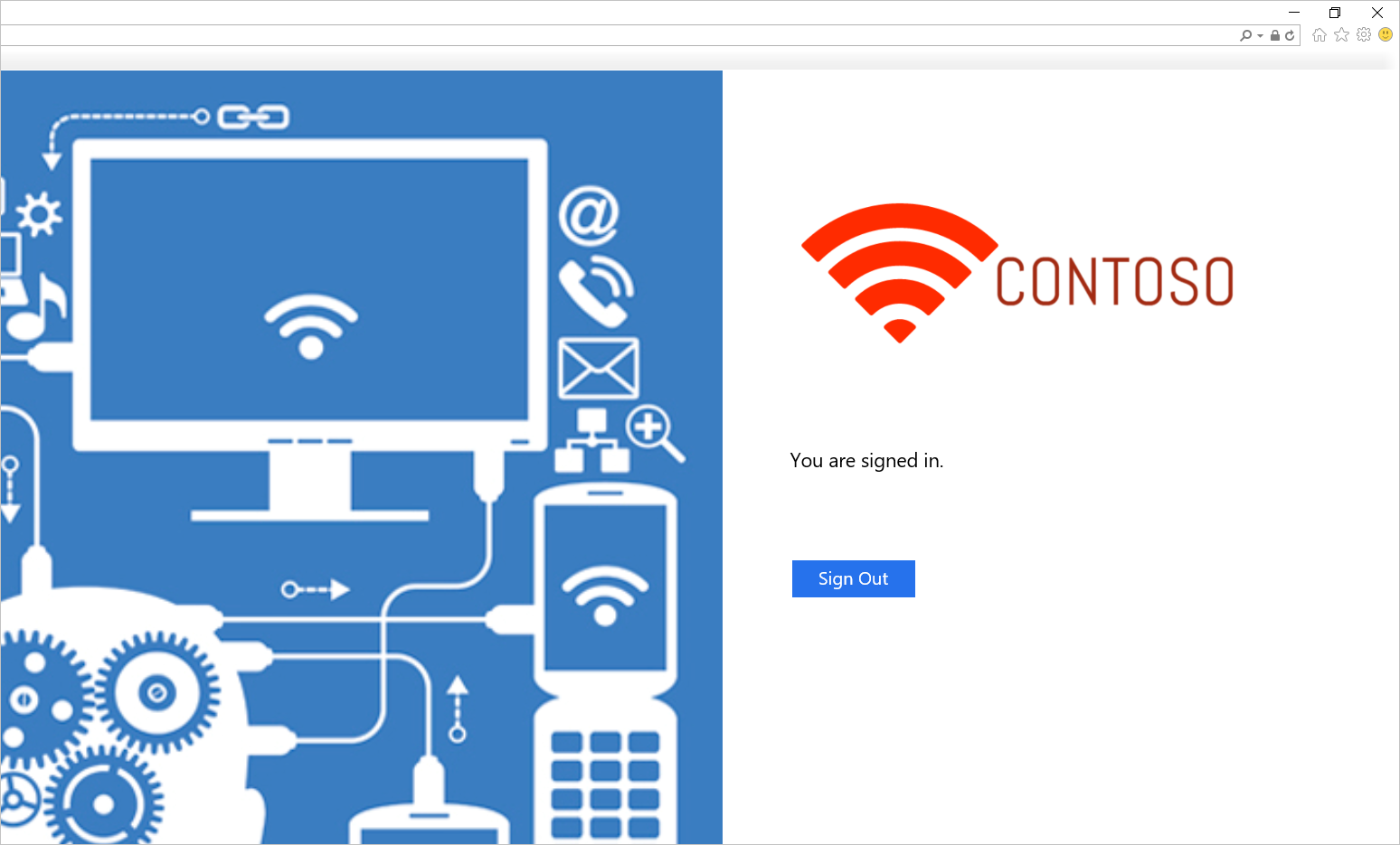
Probeer u aan te melden. Als u zich hebt aangemeld, wordt er een bericht weergegeven, zoals wordt weergegeven in de volgende schermopname.
Sjabloon voor het implementeren van AD FS in Azure
Met de sjabloon wordt een installatie van zes computers geïmplementeerd, met elk twee computers voor domeincontrollers, AD FS en WAP.
AD FS in Azure-implementatiesjabloon
U kunt een bestaand virtueel netwerk gebruiken of een nieuw virtueel netwerk maken tijdens het implementeren van deze sjabloon. De volgende tabel bevat de parameters die u kunt gebruiken om de implementatie aan te passen.
| Maatstaf | Beschrijving |
|---|---|
| Plaats | De regio waarnaar u de resources wilt implementeren. |
| Opslagrekeningtype | Het type opslagaccount dat u wilt maken. |
| VirtualNetworkUsage | Hiermee wordt aangegeven of u een nieuw virtueel netwerk wilt maken of een bestaand netwerk wilt gebruiken. |
| VirtualNetworkName | De naam van het virtuele netwerk. Verplicht voor zowel bestaand als nieuw virtueel netwerkgebruik. |
| VirtualNetworkResourceGroupName | Hiermee geeft u de naam van de resourcegroep waar het bestaande virtuele netwerk zich bevindt. Wanneer u een bestaand virtueel netwerk gebruikt, is deze optie een verplichte parameter, zodat de implementatie de id van het bestaande virtuele netwerk kan vinden. |
| VirtualNetworkAddressRange | Het adresbereik van het nieuwe virtuele netwerk. Verplicht als u een nieuw virtueel netwerk maakt. |
| InternalSubnetName | De naam van het interne subnet. Verplicht voor zowel nieuwe als bestaande opties voor virtueel netwerkgebruik. |
| InternalSubnetAddressRange | Het adresbereik van het interne subnet, dat de domeincontrollers en AD FS-servers bevat. Verplicht als u een nieuw virtueel netwerk maakt. |
| DMZSubnetAddressRange | Het adresbereik van het DMZ-subnet, dat de Windows-toepassingsproxyservers bevat. Verplicht als u een nieuw virtueel netwerk maakt. |
| DMZSubnetName | De naam van het interne subnet, dat verplicht is voor zowel nieuwe als bestaande opties voor virtueel netwerkgebruik. |
| ADDC01NICIPAddress | Het interne IP-adres van de eerste domeincontroller. Dit IP-adres is statisch toegewezen aan de domeincontroller en moet een geldig IP-adres binnen het interne subnet zijn. |
| ADDC02NICIPAddress | Het interne IP-adres van de tweede domeincontroller. Dit IP-adres is statisch toegewezen aan de domeincontroller en moet een geldig IP-adres binnen het interne subnet zijn. |
| ADFS01NICIPAddress | Het interne IP-adres van de eerste AD FS-server. Dit IP-adres is statisch toegewezen aan de AD FS-server en moet een geldig IP-adres binnen het interne subnet zijn. |
| ADFS02NICIPAddress | Het interne IP-adres van de tweede AD FS-server. Dit IP-adres is statisch toegewezen aan de AD FS-server en moet een geldig IP-adres binnen het interne subnet zijn. |
| WAP01NICIPAddress | Het interne IP-adres van de eerste WAP-server. Dit IP-adres is statisch toegewezen aan de WAP-server en moet een geldig IP-adres binnen het DMZ-subnet zijn. |
| WAP02NICIPAddress | Het interne IP-adres van de tweede WAP-server. Dit IP-adres is statisch toegewezen aan de WAP-server en moet een geldig IP-adres binnen het DMZ-subnet zijn. |
| ADFSLoadBalancerPrivateIPAddress | Het interne IP-adres van de AD FS-load balancer. Dit IP-adres is statisch toegewezen aan de load balancer en moet een geldig IP-adres binnen het interne subnet zijn. |
| ADDCVMNamePrefix | VM-naamvoorvoegsel voor domeincontrollers. |
| ADFSVMNamePrefix | VM-naamvoorvoegsel voor AD FS-servers. |
| WAPVMNamePrefix | VM-naamvoorvoegsel voor WAP-servers. |
| ADDCVMSize | De VM-grootte van de domeincontrollers. |
| ADFSVMSize | De VM-grootte van de AD FS-servers. |
| WAPVMSize | De VM-grootte van de WAP-servers. |
| AdminUserName | De naam van de lokale beheerder van de VM's. |
| AdminPassword | Het wachtwoord voor het lokale beheerdersaccount van de VM's. |
Verwante koppelingen
- Beschikbaarheidssets
- Azure Load Balancer
- Interne load balancer
- Internetgerichte belastingverdeler
- Opslagaccounts
- Virtuele Netwerken van Azure
- Koppelingen voor AD FS en webtoepassingsproxy