幾何
 流覽範例
流覽範例.NET 多平臺應用程式 UI (.NET MAUI) Geometry 類別,以及衍生自它的類別,可讓您描述 2D 圖形的幾何。 Geometry 物件可以是簡單物件,例如矩形和圓形,或從兩個或多個幾何物件建立的復合物件。 此外,可以建立更複雜的幾何,包括弧線和曲線。
類別 Geometry 是定義不同幾何類別的數個類別的父類別:
- EllipseGeometry,表示橢圓形或圓形的幾何。
- GeometryGroup,表示可將多個幾何物件合併成單一物件的容器。
- LineGeometry,表示線條的幾何。
- PathGeometry,表示由弧線、曲線、橢圓形、線條和矩形組成的複雜圖形幾何。
- RectangleGeometry,表示矩形或正方形的幾何。
注意
也有衍生 RoundRectangleGeometry 自 類別的 GeometryGroup 類別。 如需詳細資訊,請參閱 RoundRectangleGeometry。
和 GeometryShape 類別看起來很類似,因為它們都描述 2D 圖形,但有一個重要的差異。 類別 Geometry 衍生自 BindableObject 類別,而 Shape 類別則衍生自 View 類別。 因此, Shape 物件可以自行轉譯並參與配置系統,而 Geometry 物件則不能。 雖然 Shape 物件比 Geometry 物件更容易使用, Geometry 但對象比較多用途。 Shape雖然對象用來轉譯 2D 圖形,Geometry但對象可用來定義 2D 圖形的幾何區域,以及定義裁剪的區域。
下列類別具有可設定為 Geometry 物件的屬性:
- 類別 Path 會使用 Geometry 來描述其內容。 您可以將 屬性設定
Path.Data為物件,以及設定Path物件的 Fill 和 Stroke 屬性,來轉譯 GeometryGeometry 。 - 類別 VisualElement 具有 Clip 類型的 Geometry屬性,定義項目內容的外框。 Clip當屬性設定為 Geometry 物件時,只會顯示 區域內的區域Geometry。 如需詳細資訊,請參閱 使用 Geometry 裁剪。
衍生自 類別的 Geometry 類別可以分成三個類別:簡單幾何、路徑幾何和複合幾何。
簡單幾何
簡單的幾何類別為 EllipseGeometry、 LineGeometry和 RectangleGeometry。 它們可用來建立基本的幾何圖形,例如圓形、線條和矩形。 這些相同的圖形,以及更複雜的圖形,可以使用 或 將幾何對象結合在一起來建立 PathGeometry ,但這些類別提供更簡單的方法來產生這些基本幾何圖形。
EllipseGeometry
橢圓形幾何代表幾何或橢圓形或圓形,由中心點、x 半徑和 y 半徑定義。
類別 EllipseGeometry 會定義下列屬性:
- Center型別為
Point的 ,表示幾何的中心點。 - RadiusX型
double別為 的 ,表示幾何的 x 半徑值。 此屬性的預設值為 0.0。 - RadiusY型
double別為 的 ,表示幾何的 y 半徑值。 此屬性的預設值為 0.0。
這些屬性是由 BindableProperty 物件所支援,這表示這些屬性可以是數據系結的目標,並設定樣式。
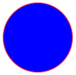
下列範例示範如何在物件中Path建立和轉譯 EllipseGeometry :
<Path Fill="Blue"
      Stroke="Red">
  <Path.Data>
    <EllipseGeometry Center="50,50"
                     RadiusX="50"
                     RadiusY="50" />
  </Path.Data>
</Path>
在此範例中,的中心 EllipseGeometry 會設定為 (50,50),而 x 半徑和 y 半徑都設定為 50。 這會建立直徑為100個裝置獨立單元的紅色圓圈,其內部繪製為藍色:
LineGeometry
折線幾何代表線條的幾何,並藉由指定線條的起點和終點來定義。
類別 LineGeometry 會定義下列屬性:
- StartPoint型別為
Point的 ,表示線條的起點。 - EndPoint型別為
Point的 ,表示線條的終點。
這些屬性是由 BindableProperty 物件所支援,這表示這些屬性可以是數據系結的目標,並設定樣式。
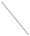
下列範例示範如何在物件中Path建立和轉譯 LineGeometry :
<Path Stroke="Black">
  <Path.Data>
    <LineGeometry StartPoint="10,20"
                  EndPoint="100,130" />
  </Path.Data>
</Path>
在此範例中, LineGeometry 從 (10,20) 到 (100,130):
注意
Fill設定呈現 的 屬性PathLineGeometry不會有任何作用,因為線條沒有內部。
RectangleGeometry
矩形幾何代表矩形或正方形的幾何,而且會以 Rect 指定其相對位置和高度和寬度的結構來定義。
類別 RectangleGeometry 會 Rect 定義 類型的 Rect屬性,代表矩形的維度。 這個屬性是由 BindableProperty 物件所支援,這表示它可以是數據系結的目標,並設定樣式。
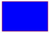
下列範例示範如何在物件中Path建立和轉譯 RectangleGeometry :
<Path Fill="Blue"
      Stroke="Red">
  <Path.Data>
    <RectangleGeometry Rect="10,10,150,100" />
  </Path.Data>
</Path>
矩形的位置和維度是由 Rect 結構所定義。 在此範例中,位置為 (10,10),寬度為150,而高度為100個裝置獨立單位:
路徑幾何
路徑幾何描述由弧線、曲線、橢圓形、線條和矩形組成的複雜圖形。
類別 PathGeometry 會定義下列屬性:
- Figures型 PathFigureCollection別為 的 ,表示描述路徑內容之 物件的集合 PathFigure 。
- FillRule型 FillRule別為 的 ,決定幾何中所包含的交集區域如何結合。 此屬性的預設值為
FillRule.EvenOdd。
這些屬性是由 BindableProperty 物件所支援,這表示這些屬性可以是數據系結的目標,並設定樣式。
如需列舉的詳細資訊 FillRule ,請參閱 .NET MAUI 圖形:填滿規則。
注意
屬性 Figures 是 ContentProperty 類別的 PathGeometry ,因此不需要從 XAML 明確設定。
PathGeometry是由物件的集合PathFigure所組成,每個PathFigure對象都會描述幾何中的圖形。 每個 PathFigure 本身是由一或多個 PathSegment 對象所組成,每個物件都會描述圖形的區段。 有許多類型的區段:
- ArcSegment,其會在兩個點之間建立橢圓形弧線。
- BezierSegment,其會在兩點之間建立立方貝塞爾曲線。
- LineSegment,它會建立兩個點之間的線條。
- PolyBezierSegment,其會建立一系列的立方貝塞爾曲線。
- PolyLineSegment,它會建立一連串的行。
- PolyQuadraticBezierSegment,其會建立一系列的二次方貝塞爾曲線。
- QuadraticBezierSegment,這會建立二次方貝塞爾曲線。
上述所有類別都是衍生自抽象 PathSegment 類。
內的 PathFigure 區段會合併成單一幾何圖形,而每個區段的終點都是下一個線段的起點。 的 StartPointPathFigure 屬性會指定繪製第一個線段的點。 每個後續區段都會從前一個區段的結束點開始。 例如,可以將 屬性設定StartPoint為 ,並使用 的屬性設定10,150來建立 LineSegmentPoint ,以定義從 到 10,150 的垂直線10,50:10,50
<Path Stroke="Black">
    <Path.Data>
        <PathGeometry>
            <PathGeometry.Figures>
                <PathFigureCollection>
                    <PathFigure StartPoint="10,50">
                        <PathFigure.Segments>
                            <PathSegmentCollection>
                                <LineSegment Point="10,150" />
                            </PathSegmentCollection>
                        </PathFigure.Segments>
                    </PathFigure>
                </PathFigureCollection>
            </PathGeometry.Figures>
        </PathGeometry>
    </Path.Data>
</Path>
使用 對象的組合PathSegment,以及使用 中的PathGeometry多個物件,即可建立更複雜的PathFigure幾何。
建立 ArcSegment
會 ArcSegment 建立兩個點之間的橢圓形弧線。 橢圓形弧線是由其起點和終點、x 軸和 y 軸旋轉因數、指出弧線是否應該大於 180 度的值,以及描述弧線繪製方向的值所定義。
類別 ArcSegment 會定義下列屬性:
- Point型
Point別為 的 ,表示橢圓形弧線的端點。此屬性的預設值為 (0,0)。 - Size型
Size別為 的 ,表示弧線的 x 和 y 半徑。此屬性的預設值為 (0,0)。 - RotationAngle型
double別為 的 ,表示橢圓形繞 x 軸旋轉的度數。 這個屬性的預設值為 0。 - SweepDirection型 SweepDirection別為 的 ,指定繪製弧線的方向。 此屬性的預設值為
SweepDirection.CounterClockwise。 - IsLargeArc型
bool別為 的 ,指出弧線是否應該大於180度。 此屬性的預設值為false。
這些屬性是由 BindableProperty 物件所支援,這表示這些屬性可以是數據系結的目標,並設定樣式。
注意
類別 ArcSegment 不包含弧線起點的屬性。它只會定義它所代表之弧線的終點。 弧線的起點是 加入 的PathFigureArcSegment目前點。
SweepDirection 列舉會定義下列成員:
- CounterClockwise,指定弧線會以逆時針方向繪製。
- Clockwise,指定弧線會以順時針方向繪製。
下列範例示範如何在物件中Path建立和轉譯 ArcSegment :
<Path Stroke="Black">
    <Path.Data>
        <PathGeometry>
            <PathGeometry.Figures>
                <PathFigureCollection>
                    <PathFigure StartPoint="10,10">
                        <PathFigure.Segments>
                            <PathSegmentCollection>
                                <ArcSegment Size="100,50"
                                            RotationAngle="45"
                                            IsLargeArc="True"
                                            SweepDirection="CounterClockwise"
                                            Point="200,100" />
                            </PathSegmentCollection>
                        </PathFigure.Segments>
                    </PathFigure>
                </PathFigureCollection>
            </PathGeometry.Figures>
        </PathGeometry>
    </Path.Data>
</Path>
在此範例中,橢圓形弧線是從 (10,10) 繪製到 (200,100)。
建立 BezierSegment
在 BezierSegment 兩點之間建立立方貝塞爾曲線。 立方貝塞爾曲線是由四個點所定義:起點、終點和兩個控制點。
類別 BezierSegment 會定義下列屬性:
- Point1型別為
Point的 ,表示曲線的第一個控制點。 此屬性的預設值為 (0,0)。 - Point2型
Point別為 的 ,表示曲線的第二個控制點。 此屬性的預設值為 (0,0)。 - Point3型
Point別為 的 ,表示曲線的終點。 此屬性的預設值為 (0,0)。
這些屬性是由 BindableProperty 物件所支援,這表示這些屬性可以是資料系結的目標,並設定樣式。
注意
類別 BezierSegment 不包含曲線起點的屬性。 曲線的起點是 加入 的目前點 PathFigureBezierSegment 。
三次方貝茲曲線的兩個控制點的行為就像磁石,吸引了部分否則會向自己走直線並產生曲線。 第一個控制點會影響曲線的開始部分。 第二個控制點會影響曲線的結束部分。 曲線不一定通過任一控制點。 相反地,每個控制點都會將線條的一部分向本身移動,但不會透過本身移動。
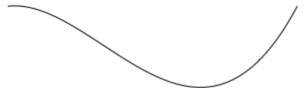
下列範例示範如何在 物件中 Path 建立和轉譯 BezierSegment :
<Path Stroke="Black">
    <Path.Data>
        <PathGeometry>
            <PathGeometry.Figures>
                <PathFigureCollection>
                    <PathFigure StartPoint="10,10">
                        <PathFigure.Segments>
                            <PathSegmentCollection>
                                <BezierSegment Point1="100,0"
                                               Point2="200,200"
                                               Point3="300,10" />
                            </PathSegmentCollection>
                        </PathFigure.Segments>
                    </PathFigure>
                </PathFigureCollection>
            </PathGeometry.Figures>
        </PathGeometry>
    </Path.Data>
</Path>
在此範例中,三次方貝茲曲線是從 (10,10) 繪製到 (300,10)。 曲線有兩個控制點在 (100,0) 和 (200,200):
建立 LineSegment
會 LineSegment 建立兩個點之間的線條。
類別 LineSegment 會 Point 定義 型 Point 別 的 屬性,代表線段的終點。 這個屬性的預設值是 (0,0),而且是由 BindableProperty 物件所支援,這表示它可以是資料系結的目標,並設定樣式。
注意
類別 LineSegment 不包含行起點的屬性。 它只會定義終點。 線條的起點是 加入 的目前點 PathFigureLineSegment 。
下列範例示範如何在 物件中 Path 建立和轉譯 LineSegment 物件:
<Path Stroke="Black"
      Aspect="Uniform"
      HorizontalOptions="Start">
    <Path.Data>
        <PathGeometry>
            <PathGeometry.Figures>
                <PathFigureCollection>
                    <PathFigure IsClosed="True"
                                StartPoint="10,100">
                        <PathFigure.Segments>
                            <PathSegmentCollection>
                                <LineSegment Point="100,100" />
                                <LineSegment Point="100,50" />
                            </PathSegmentCollection>
                        </PathFigure.Segments>
                    </PathFigure>
                </PathFigureCollection>
            </PathGeometry.Figures>
        </PathGeometry>
    </Path.Data>
</Path>
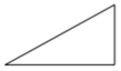
在此範例中,線段是從 (10,100) 到 (100,100), 從 (100,100) 到 (100,50) 繪製。 此外, PathFigure 會關閉 ,因為它的 IsClosed 屬性設定為 true 。 這會導致繪製三角形:
建立 PolyBezierSegment
會 PolyBezierSegment 建立一或多個立方貝茲曲線。
類別 PolyBezierSegment 會 Points 定義 類型的 PointCollection 屬性,代表定義 的 PolyBezierSegment 點。 PointCollection是 ObservableCollection 物件的 Point 。 這個屬性是由 BindableProperty 物件所支援,這表示它可以是資料系結的目標,並設定樣式。
注意
類別 PolyBezierSegment 不包含曲線起點的屬性。 曲線的起點是 加入 的目前點 PathFigurePolyBezierSegment 。
下列範例示範如何在 物件中 Path 建立和轉譯 PolyBezierSegment :
<Path Stroke="Black">
    <Path.Data>
        <PathGeometry>
            <PathGeometry.Figures>
                <PathFigureCollection>
                    <PathFigure StartPoint="10,10">
                        <PathFigure.Segments>
                            <PathSegmentCollection>
                                <PolyBezierSegment Points="0,0 100,0 150,100 150,0 200,0 300,10" />
                            </PathSegmentCollection>
                        </PathFigure.Segments>
                    </PathFigure>
                </PathFigureCollection>
            </PathGeometry.Figures>
        </PathGeometry>
    </Path.Data>
</Path>
在此範例中,會 PolyBezierSegment 指定兩個立方貝茲曲線。 第一條曲線是從 (10,10) 到 (150,100) ,控制點為 (0,0),另一個控制點為 (100,0)。 第二條曲線是從(150,100)到(300,10),控制點為(150,0),另一個控制點為(200,0):
建立 PolyLineSegment
會 PolyLineSegment 建立一或多個線段。
類別 PolyLineSegment 會 Points 定義 類型的 PointCollection 屬性,代表定義 的 PolyLineSegment 點。 PointCollection是 ObservableCollection 物件的 Point 。 這個屬性是由 BindableProperty 物件所支援,這表示它可以是資料系結的目標,並設定樣式。
注意
類別 PolyLineSegment 不包含行起點的屬性。 線條的起點是 加入 的目前點 PathFigurePolyLineSegment 。
下列範例示範如何在 物件中 Path 建立和轉譯 PolyLineSegment :
<Path Stroke="Black">
    <Path.Data>
        <PathGeometry>
            <PathGeometry.Figures>
                <PathFigure StartPoint="10,10">
                    <PathFigure.Segments>
                        <PolyLineSegment Points="50,10 50,50" />
                    </PathFigure.Segments>
                </PathFigure>
            </PathGeometry.Figures>
        </PathGeometry>
    </Path.Data>
</Path>
在此範例中,會 PolyLineSegment 指定兩行。 第一行是從 (10,10) 到 (50,10),第二行是從 (50,10) 到 (50,50):

建立 PolyQuadraticBezierSegment
PolyQuadraticBezierSegment會建立一或多個二次方貝茲曲線。
類別 PolyQuadraticBezierSegment 會 Points 定義 類型的 PointCollection 屬性,代表定義 的 PolyQuadraticBezierSegment 點。 PointCollection是 ObservableCollection 物件的 Point 。 這個屬性是由 BindableProperty 物件所支援,這表示它可以是資料系結的目標,並設定樣式。
注意
類別 PolyQuadraticBezierSegment 不包含曲線起點的屬性。 曲線的起點是 加入 的目前點 PathFigurePolyQuadraticBezierSegment 。
下列範例示範如何在 物件中 Path 建立和轉譯 PolyQuadraticBezierSegment :
<Path Stroke="Black">
    <Path.Data>
        <PathGeometry>
            <PathGeometry.Figures>
                <PathFigureCollection>
                    <PathFigure StartPoint="10,10">
                        <PathFigure.Segments>
                            <PathSegmentCollection>
                                <PolyQuadraticBezierSegment Points="100,100 150,50 0,100 15,200" />
                            </PathSegmentCollection>
                        </PathFigure.Segments>
                    </PathFigure>
                </PathFigureCollection>
            </PathGeometry.Figures>
        </PathGeometry>
    </Path.Data>
</Path>
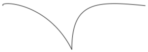
在此範例中,會 PolyQuadraticBezierSegment 指定兩個 Bezier 曲線。 第一條曲線是從(10,10)到(150,50),控制點為(100,100)。 第二條曲線是從(100,100)到(15,200),控制點為 (0,100):
建立 QuadraticBezierSegment
在 QuadraticBezierSegment 兩點之間建立二次方貝茲曲線。
類別 QuadraticBezierSegment 會定義下列屬性:
這些屬性是由 BindableProperty 物件所支援,這表示這些屬性可以是資料系結的目標,並設定樣式。
注意
類別 QuadraticBezierSegment 不包含曲線起點的屬性。 曲線的起點是 加入 的目前點 PathFigureQuadraticBezierSegment 。
下列範例示範如何在 物件中 Path 建立和轉譯 QuadraticBezierSegment :
<Path Stroke="Black">
    <Path.Data>
        <PathGeometry>
            <PathGeometry.Figures>
                <PathFigureCollection>
                    <PathFigure StartPoint="10,10">
                        <PathFigure.Segments>
                            <PathSegmentCollection>
                                <QuadraticBezierSegment Point1="200,200"
                                                        Point2="300,10" />
                            </PathSegmentCollection>
                        </PathFigure.Segments>
                    </PathFigure>
                </PathFigureCollection>
            </PathGeometry.Figures>
        </PathGeometry>
    </Path.Data>
</Path>
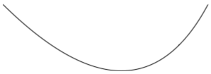
在此範例中,二次方貝茲曲線是從 (10,10) 繪製到 (300,10)。 曲線的控制點位於 (200,200):
建立複雜的幾何
您可以使用 物件的組合 PathSegment 來建立更複雜的幾何。 下列範例會使用 BezierSegment 、 LineSegment 和 ArcSegment 建立圖形:
<Path Stroke="Black">
    <Path.Data>
        <PathGeometry>
            <PathGeometry.Figures>
                <PathFigure StartPoint="10,50">
                    <PathFigure.Segments>
                        <BezierSegment Point1="100,0"
                                       Point2="200,200"
                                       Point3="300,100"/>
                        <LineSegment Point="400,100" />
                        <ArcSegment Size="50,50"
                                    RotationAngle="45"
                                    IsLargeArc="True"
                                    SweepDirection="Clockwise"
                                    Point="200,100"/>
                    </PathFigure.Segments>
                </PathFigure>
            </PathGeometry.Figures>
        </PathGeometry>
    </Path.Data>
</Path>
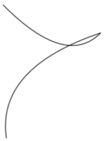
在此範例中, BezierSegment 會先使用四個點來定義 。 然後,此範例會將 LineSegment 繪製在 的結束點 BezierSegment 之間繪製到 所 LineSegment 指定的點。 最後, ArcSegment 會從 的終點 LineSegment 繪製到 所 ArcSegment 指定的點。
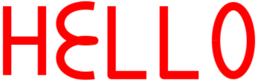
使用 內的 PathGeometry 多個 PathFigure 物件,即可建立更複雜的幾何。 下列範例會從七 PathFigure 個 PathGeometry 物件建立 ,其中有些物件包含多個 PathSegment 物件:
<Path Stroke="Red"
      StrokeThickness="12"
      StrokeLineJoin="Round">
    <Path.Data>
        <PathGeometry>
            <!-- H -->
            <PathFigure StartPoint="0,0">
                <LineSegment Point="0,100" />
            </PathFigure>
            <PathFigure StartPoint="0,50">
                <LineSegment Point="50,50" />
            </PathFigure>
            <PathFigure StartPoint="50,0">
                <LineSegment Point="50,100" />
            </PathFigure>

            <!-- E -->
            <PathFigure StartPoint="125, 0">
                <BezierSegment Point1="60, -10"
                               Point2="60, 60"
                               Point3="125, 50" />
                <BezierSegment Point1="60, 40"
                               Point2="60, 110"
                               Point3="125, 100" />
            </PathFigure>

            <!-- L -->
            <PathFigure StartPoint="150, 0">
                <LineSegment Point="150, 100" />
                <LineSegment Point="200, 100" />
            </PathFigure>

            <!-- L -->
            <PathFigure StartPoint="225, 0">
                <LineSegment Point="225, 100" />
                <LineSegment Point="275, 100" />
            </PathFigure>

            <!-- O -->
            <PathFigure StartPoint="300, 50">
                <ArcSegment Size="25, 50"
                            Point="300, 49.9"
                            IsLargeArc="True" />
            </PathFigure>
        </PathGeometry>
    </Path.Data>
</Path>
在此範例中,「Hello」 一詞是使用 和 BezierSegment 物件的組合 LineSegment 來繪製,以及單 ArcSegment 一物件:
複合幾何
您可以使用 來建立 GeometryGroup 複合幾何物件。 類別 GeometryGroup 會從一或多個 Geometry 物件建立複合幾何。 任何數目 Geometry 的物件都可以加入至 GeometryGroup 。
類別 GeometryGroup 會定義下列屬性:
- Children型 GeometryCollection 別為 的 ,指定定義 的物件 GeometryGroup 。 GeometryCollection是
ObservableCollection物件的 Geometry 。 - FillRule型 FillRule 別為 的 ,指定 中的交集區域 GeometryGroup 如何結合。 此屬性的預設值為
FillRule.EvenOdd。
這些屬性是由 BindableProperty 物件所支援,這表示這些屬性可以是資料系結的目標,並設定樣式。
注意
屬性 Children 是 ContentProperty 類別的 GeometryGroup ,因此不需要從 XAML 明確設定。
如需列舉的詳細資訊 FillRule ,請參閱 填滿規則 。
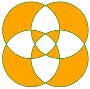
若要繪製複合幾何,請將所需的 Geometry 物件設定為 的 GeometryGroup 子系,並以 物件顯示它們 Path 。 下列 XAML 顯示下列範例:
<Path Stroke="Green"
      StrokeThickness="2"
      Fill="Orange">
    <Path.Data>
        <GeometryGroup>
            <EllipseGeometry RadiusX="100"
                             RadiusY="100"
                             Center="150,150" />
            <EllipseGeometry RadiusX="100"
                             RadiusY="100"
                             Center="250,150" />
            <EllipseGeometry RadiusX="100"
                             RadiusY="100"
                             Center="150,250" />
            <EllipseGeometry RadiusX="100"
                             RadiusY="100"
                             Center="250,250" />
        </GeometryGroup>
    </Path.Data>
</Path>
在此範例中,會結合四 EllipseGeometry 個具有相同 x 半徑和 Y 半徑座標但具有不同中心座標的物件。 這會建立四個重迭的圓形,其內部會因為預設 EvenOdd 填滿規則而填滿橙色:
RoundRectangleGeometry
圓矩形幾何代表矩形或正方形的幾何,具有圓角,而且是由圓角半徑和 Rect 結構所定義,指定其相對位置和高度和寬度的結構。
RoundRectangleGeometry衍生自 類別的 GeometryGroup 類別會定義下列屬性:
- CornerRadius型別為
CornerRadius的 ,這是幾何的圓角半徑。 - Rect型
Rect別為 的 ,表示矩形的維度。
這些屬性是由 BindableProperty 物件所支援,這表示這些屬性可以是資料系結的目標,並設定樣式。
注意
所使用的 RoundRectangleGeometry 填滿規則為 FillRule.Nonzero 。 如需填滿規則的詳細資訊,請參閱 填滿規則 。
下列範例示範如何在 物件中 Path 建立和轉譯 RoundRectangleGeometry :
<Path Fill="Blue"
      Stroke="Red">
    <Path.Data>
        <RoundRectangleGeometry CornerRadius="5"
                                Rect="10,10,150,100" />
    </Path.Data>
</Path>
矩形的位置和維度是由 Rect 結構所定義。 在此範例中,位置為 (10,10),寬度為 150,而高度為 100 個裝置獨立單位。 此外,矩形邊角會以 5 個裝置獨立單位的半徑四捨五入。
使用幾何裁剪
類別 VisualElement 具有 Clip 類型的 Geometry 屬性,定義專案內容的外框。 Clip當 屬性設定為 Geometry 物件時,只會顯示 區域內的區域 Geometry 。
下列範例示範如何使用 Geometry 物件作為 的 Image 剪輯區域:
<Image Source="monkeyface.png">
    <Image.Clip>
        <EllipseGeometry RadiusX="100"
                         RadiusY="100"
                         Center="180,180" />
    </Image.Clip>
</Image>
在此範例中, EllipseGeometry 具有 RadiusX 和 RadiusY 值為 100 的 ,且 Center 值為 (180,180) 會設定為 Clip 的 Image 屬性。 只會顯示橢圓形區域內影像的一部分:

注意
簡單的幾何、路徑幾何和複合幾何都可以用來裁剪 VisualElement 物件。
其他功能
類別 GeometryHelper 提供下列協助程式方法:
- FlattenGeometry,其會將 扁平化 Geometry 為 PathGeometry 。
- FlattenCubicBezier,將立方貝茲曲線壓平成
List<Point>集合。 - FlattenQuadraticBezier,將二次方貝茲曲線壓平成
List<Point>集合。 - FlattenArc,其會將橢圓形弧線扁平化為
List<Point>集合。
意見反應
即將登場:在 2024 年,我們將逐步淘汰 GitHub 問題作為內容的意見反應機制,並將它取代為新的意見反應系統。 如需詳細資訊,請參閱:https://aka.ms/ContentUserFeedback。
提交並檢視相關的意見反應