Direct2D には、さまざまな一般的な画像操作を実行する効果のライブラリが付属しています。 効果の完全な一覧については、 組み込みの効果 に関するトピックを参照してください。 組み込みの効果では実現できない機能の場合、Direct2D では、標準 の HLSL を使用して独自のカスタム効果を記述できます。 これらのカスタム効果は、Direct2D に付属する組み込みの効果と共に使用できます。
ピクセル、頂点、コンピューティング シェーダーの完全な効果の例については、 D2DCustomEffects SDK サンプルを参照してください。
このトピックでは、完全に機能するカスタム効果を設計および作成するために必要な手順と概念について説明します。
概要: 効果の内部とは何ですか?
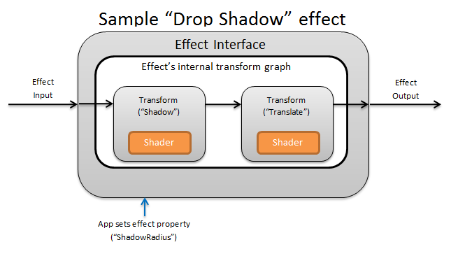
概念的には、 Direct2D 効果は、明るさの変更、イメージの飽和解除、または上に示すようにドロップ シャドウの作成などのイメージング タスクを実行します。 アプリでは、単純です。 0 個以上の入力イメージを受け入れ、操作を制御する複数のプロパティを公開し、1 つの出力イメージを生成できます。
エフェクト作成者が担当するカスタム効果には、次の 4 つの異なる部分があります。
- 効果インターフェイス: 効果インターフェイスは、アプリがカスタム効果と対話する方法 (効果が受け入れる入力の数や使用可能なプロパティなど) を概念的に定義します。 効果インターフェイスは、実際のイメージング操作を含む変換グラフを管理します。
- 変換グラフ: 各効果は、個々の変換で構成される内部変換グラフを作成します。 各変換は、1 つのイメージ操作を表します。 この効果は、これらの変換をグラフにリンクして、目的のイメージング効果を実行します。 効果は、効果の外部プロパティに対する変更に応じて、変換を追加、削除、変更、および並べ替えることができます。
- 変換: 変換は、1 つのイメージ操作を表します。 そのメイン目的は、出力ピクセルごとに実行されるシェーダーを格納することです。 そのため、シェーダーのロジックに基づいて出力イメージの新しいサイズを計算します。 また、シェーダーが要求された出力領域をレンダリングするために読み取る必要がある入力イメージの領域も計算する必要があります。
- シェーダー: GPU 上の変換の入力に対してシェーダーが実行されます (アプリが Direct3D デバイスを作成するときにソフトウェア レンダリングが指定されている場合は CPU)。 効果シェーダーはハイ レベル シェーディング言語 (HLSL) で記述され、エフェクトのコンパイル中にバイト コードにコンパイルされ、実行時にエフェクトによって読み込まれます。 このリファレンス ドキュメントでは、 Direct2D 準拠の HLSL を記述する方法について説明します。 Direct3D ドキュメントには、基本的な HLSL の概要が含まれています。
エフェクト インターフェイスの作成
エフェクト インターフェイスは、アプリがカスタム効果と対話する方法を定義します。 効果インターフェイスを作成するには、クラスで ID2D1EffectImpl を実装し、その効果 (名前、入力カウント、プロパティなど) を記述するメタデータを定義し、 Direct2D で使用するカスタム効果を登録するメソッドを作成する必要があります。
効果インターフェイスのすべてのコンポーネントが実装されると、クラスのヘッダーは次のように表示されます。
#include <d2d1_1.h>
#include <d2d1effectauthor.h>
#include <d2d1effecthelpers.h>

// Example GUID used to uniquely identify the effect. It is passed to Direct2D during
// effect registration, and used by the developer to identify the effect for any
// ID2D1DeviceContext::CreateEffect calls in the app. The app should create
// a unique name for the effect, as well as a unique GUID using a generation tool.
DEFINE_GUID(CLSID_SampleEffect, 0x00000000, 0x0000, 0x0000, 0x00, 0x00, 0x00, 0x00, 0x00, 0x00, 0x00, 0x00);

class SampleEffect : public ID2D1EffectImpl
{
public:
    // 2.1 Declare ID2D1EffectImpl implementation methods.
    IFACEMETHODIMP Initialize(
        _In_ ID2D1EffectContext* pContextInternal,
        _In_ ID2D1TransformGraph* pTransformGraph
        );

    IFACEMETHODIMP PrepareForRender(D2D1_CHANGE_TYPE changeType);
    IFACEMETHODIMP SetGraph(_In_ ID2D1TransformGraph* pGraph);

    // 2.2 Declare effect registration methods.
    static HRESULT Register(_In_ ID2D1Factory1* pFactory);
    static HRESULT CreateEffect(_Outptr_ IUnknown** ppEffectImpl);

    // 2.3 Declare IUnknown implementation methods.
    IFACEMETHODIMP_(ULONG) AddRef();
    IFACEMETHODIMP_(ULONG) Release();
    IFACEMETHODIMP QueryInterface(_In_ REFIID riid, _Outptr_ void** ppOutput);

private:
    // Constructor should be private since it should never be called externally.
    SampleEffect();

    LONG m_refCount; // Internal ref count used by AddRef() and Release() methods.
};
ID2D1EffectImpl を実装する
ID2D1EffectImpl インターフェイスには、実装する必要がある 3 つのメソッドが含まれています。
Initialize(ID2D1EffectContext *pContextInternal, ID2D1TransformGraph *pTransformGraph)
Direct2D は、アプリによって ID2D1DeviceContext::CreateEffect メソッドが呼び出された後に Initialize メソッドを呼び出します。 このメソッドを使用すると、内部初期化や、効果に必要なその他の操作を実行できます。 さらに、これを使用して、効果の初期変換グラフを作成することもできます。
SetGraph(ID2D1TransformGraph *pTransformGraph)
Direct2D は、効果への入力の数が変更されたときに SetGraph メソッドを呼び出します。 ほとんどの効果には一定の数の入力が含まれますが、 複合効果 のような他の効果は可変の入力数をサポートします。 このメソッドを使用すると、入力数の変化に応じて変換グラフを更新できます。 効果が変数入力カウントをサポートしていない場合、このメソッドは単にE_NOTIMPLを返すことができます。
PrepareForRender (D2D1_CHANGE_TYPE changeType)
PrepareForRender メソッドを使用すると、外部の変更に応じてすべての操作を実行する効果を得られます。 Direct2D は、次の少なくとも 1 つが当てはまる場合に効果をレンダリングする直前に、このメソッドを呼び出します。
- 効果は以前に初期化されていますが、まだ描画されていません。
- 効果プロパティは、前回の描画呼び出し以降に変更されました。
- 呼び出し元の Direct2D コンテキスト (DPI など) の状態は、前回の描画呼び出し以降に変更されています。
効果の登録メソッドとコールバック メソッドを実装する
アプリは、インスタンス化する前に Direct2D に効果を登録する必要があります。 この登録のスコープは Direct2D ファクトリのインスタンスであり、アプリが実行されるたびに繰り返す必要があります。 この登録を有効にするには、カスタム効果によって、一意の GUID、効果を登録するパブリック メソッド、および効果のインスタンスを返すプライベート コールバック メソッドが定義されます。
GUID を定義する
Direct2D への登録の効果を一意に識別する GUID を定義する必要があります。 アプリは、 ID2D1DeviceContext::CreateEffect を呼び出すときに、同じ を使用して効果を識別します。
このコードは、効果のためにこのような GUID を定義する方法を示しています。 guidgen.exe などの GUID 生成ツールを使用して、独自の一意の GUID を作成する必要があります。
// Example GUID used to uniquely identify the effect. It is passed to Direct2D during
// effect registration, and used by the developer to identify the effect for any
// ID2D1DeviceContext::CreateEffect calls in the app. The app should create
// a unique name for the effect, as well as a unique GUID using a generation tool.
DEFINE_GUID(CLSID_SampleEffect, 0x00000000, 0x0000, 0x0000, 0x00, 0x00, 0x00, 0x00, 0x00, 0x00, 0x00, 0x00);
パブリック登録メソッドを定義する
次に、 Direct2D に効果を登録するためにアプリが呼び出すパブリック メソッドを定義します。 効果の登録は Direct2D ファクトリのインスタンスに固有であるため、メソッドは ID2D1Factory1 インターフェイスをパラメーターとして受け取ります。 効果を登録するために、 メソッドは ID2D1Factory1 パラメーターで ID2D1Factory1::RegisterEffectFromString API を呼び出します。
この API は、効果のメタデータ、入力、およびプロパティを記述する XML 文字列を受け入れます。 効果のメタデータは情報提供のみを目的としており、 ID2D1Properties インターフェイスを使用してアプリからクエリを実行できます。 一方、入力データとプロパティ データは Direct2D によって使用され、効果の機能を表します。
最小限のサンプル効果の XML 文字列を次に示します。 XML へのカスタム プロパティの追加については、「効果へのカスタム プロパティの追加」セクションを参照してください。
#define XML(X) TEXT(#X) // This macro creates a single string from multiple lines of text.

PCWSTR pszXml =
    XML(
        <?xml version='1.0'?>
        <Effect>
            <!-- System Properties -->
            <Property name='DisplayName' type='string' value='SampleEffect'/>
            <Property name='Author' type='string' value='Contoso'/>
            <Property name='Category' type='string' value='Sample'/>
            <Property name='Description' type='string' value='This is a demo effect.'/>
            <Inputs>
                <Input name='SourceOne'/>
                <!-- <Input name='SourceTwo'/> -->
                <!-- Additional inputs go here. -->
            </Inputs>
            <!-- Custom Properties go here. -->
        </Effect>
        );
エフェクト ファクトリ コールバック メソッドを定義する
効果は、1 つの IUnknown** パラメーターを介して効果のインスタンスを返すプライベート コールバック メソッドも提供する必要があります。 このメソッドへのポインターは、PD2D1_EFFECT_FACTORY\ パラメーターを使用して ID2D1Factory1::RegisterEffectFromString API を介して効果が登録されるときに Direct2D に提供されます。
HRESULT __stdcall SampleEffect::CreateEffect(_Outptr_ IUnknown** ppEffectImpl)
{
    // This code assumes that the effect class initializes its reference count to 1.
    *ppEffectImpl = static_cast<ID2D1EffectImpl*>(new SampleEffect());

    if (*ppEffectImpl == nullptr)
    {
        return E_OUTOFMEMORY;
    }

    return S_OK;
}
IUnknown インターフェイスを実装する
最後に、COM との互換性のために IUnknown インターフェイスを実装する必要があります。
効果の変換グラフの作成
効果では、いくつかの異なる変換 (個々の画像操作) を使用して、目的のイメージング効果を作成できます。 これらの変換を入力イメージに適用する順序を制御するために、効果によって変換グラフに配置されます。 変換グラフでは、 Direct2D に含まれる効果と変換、および効果作成者によって作成されたカスタム変換を利用できます。
Direct2D に含まれる変換の使用
これらは、 Direct2D で提供される最も一般的に使用される変換です。
- ID2D1BlendTransform: この変換では、ブレンドの説明に基づいて任意の数の入力がブレンドされます。ブレンドの例については、 D2D1_BLEND_DESCRIPTION トピックと Direct2D 複合効果モードのサンプル を参照してください。 この変換は、 ID2D1EffectContext::CreateBlendTransform メソッドによって返されます。
- ID2D1BorderTransform: この変換は、指定された D2D1_EXTEND_MODE に従ってイメージの出力サイズを拡張します。 この変換は、 ID2D1EffectContext::CreateBorderTransform メソッドによって返されます。
- ID2D1OffsetTransform: この変換は、入力を任意のピクセル数だけオフセット (変換) します。 この変換は、 ID2D1EffectContext::CreateOffsetTransform メソッドによって返されます。
- 既存の効果は、 ID2D1EffectContext::CreateTransformNodeFromEffect メソッドを使用して、変換グラフ作成の目的で変換として扱うことができます。
単一ノード変換グラフの作成
変換を作成したら、効果の入力を変換の入力に接続し、変換の出力をエフェクトの出力に接続する必要があります。 効果に 1 つの変換のみが含まれている場合は、 ID2D1TransformGraph::SetSingleTransformNode メソッドを 使用して簡単にこれを実現できます。
指定された ID2D1TransformGraph パラメーターを使用して、効果の Initialize メソッドまたは SetGraph メソッドで変換を作成または変更できます。 このパラメーターを使用できない別のメソッドで変換グラフに変更を加える必要がある場合は、 ID2D1TransformGraph パラメーターをクラスのメンバー変数として保存し、 PrepareForRender やカスタム プロパティ コールバック メソッドなどの他の場所にアクセスできます。
Initialize メソッドの例を次に示します。 このメソッドは、各軸で画像を 100 ピクセルオフセットする単一ノード変換グラフを作成します。
IFACEMETHODIMP SampleEffect::Initialize(
    _In_ ID2D1EffectContext* pEffectContext,
    _In_ ID2D1TransformGraph* pTransformGraph
    )
{
    HRESULT hr = pEffectContext->CreateOffsetTransform(
        D2D1::Point2L(100,100),  // Offsets the input by 100px in each axis.
        &m_pOffsetTransform
        );

    if (SUCCEEDED(hr))
    {
        // Connects the effect's input to the transform's input, and connects
        // the transform's output to the effect's output.
        hr = pTransformGraph->SetSingleTransformNode(m_pOffsetTransform);
    }

    return hr;
}
マルチノード変換グラフの作成
エフェクトの変換グラフに複数の変換を追加すると、1 つの統一効果としてアプリに表示される複数の画像操作をエフェクトで内部的に実行できます。
前述のように、効果の変換グラフは、効果の Initialize メソッドで受け取った ID2D1TransformGraph パラメーターを使用して、任意の効果メソッドで編集できます。 そのインターフェイスの次の API を使用して、効果の変換グラフを作成または変更できます。
AddNode(ID2D1TransformNode *pNode)
実際には、 AddNode メソッドは、変換を効果で "登録" し、変換を他の変換グラフ メソッドと共に使用する前に呼び出す必要があります。
ConnectToEffectInput(UINT32 toEffectInputIndex, ID2D1TransformNode *pNode, UINT32 toNodeInputIndex)
ConnectToEffectInput メソッドは、効果のイメージ入力を変換の入力に接続します。 同じ効果入力を複数の変換に接続できます。
ConnectNode(ID2D1TransformNode *pFromNode, ID2D1TransformNode *pToNode, UINT32 toNodeInputIndex)
ConnectNode メソッドは、変換の出力を別の変換の入力に接続します。 変換出力は、複数の変換に接続できます。
SetOutputNode(ID2D1TransformNode *pNode)
SetOutputNode メソッドは、変換の出力をエフェクトの出力に接続します。 効果には出力が 1 つしかないため、"出力ノード" として指定できる変換は 1 つだけです。
このコードでは、2 つの個別の変換を使用して統合効果を作成します。 この場合、効果は翻訳されたドロップ シャドウです。
IFACEMETHODIMP SampleEffect::Initialize(
    _In_ ID2D1EffectContext* pEffectContext,
    _In_ ID2D1TransformGraph* pTransformGraph
    )
{
    // Create the shadow effect.
    HRESULT hr = pEffectContext->CreateEffect(CLSID_D2D1Shadow, &m_pShadowEffect);

    // Create the shadow transform from the shadow effect.
    if (SUCCEEDED(hr))
    {
        hr = pEffectContext->CreateTransformNodeFromEffect(m_pShadowEffect, &m_pShadowTransform);
    }

    // Create the offset transform.
    if (SUCCEEDED(hr))
    {
        hr = pEffectContext->CreateOffsetTransform(
            D2D1::Point2L(0,0),
            &m_pOffsetTransform
            );
    }

    // Register both transforms with the effect graph.
    if (SUCCEEDED(hr))
    {
        hr = pTransformGraph->AddNode(m_pShadowTransform);
    }

    if (SUCCEEDED(hr))
    {
        hr = pTransformGraph->AddNode(m_pOffsetTransform);
    }

    // Connect the custom effect's input to the shadow transform's input.
    if (SUCCEEDED(hr))
    {
        hr = pTransformGraph->ConnectToEffectInput(
            0,                  // Input index of the effect.
            m_pShadowTransform, // The receiving transform.
            0                   // Input index of the receiving transform.
            );
    }

    // Connect the shadow transform's output to the offset transform's input.
    if (SUCCEEDED(hr))
    {
        hr = pTransformGraph->ConnectNode(
            m_pShadowTransform, // 'From' node.
            m_pOffsetTransform, // 'To' node.
            0                   // Input index of the 'to' node. There is only one output for the 'From' node.
            );
    }

    // Connect the offset transform's output to the custom effect's output.
    if (SUCCEEDED(hr))
    {
        hr = pTransformGraph->SetOutputNode(
            m_pOffsetTransform
            );
    }

    return hr;
}
効果にカスタム プロパティを追加する
効果では、実行時にアプリで効果の動作を変更できるようにするカスタム プロパティを定義できます。 カスタム効果のプロパティを定義するには、次の 3 つの手順があります。
エフェクトの登録データにプロパティ メタデータを追加する
登録 XML にプロパティを追加する
Direct2D へのエフェクトの初期登録中に、カスタム 効果のプロパティを定義する必要があります。 まず、パブリック登録メソッドのエフェクトの登録 XML を新しいプロパティで更新する必要があります。
PCWSTR pszXml =
    TEXT(
        <?xml version='1.0'?>
        <Effect>
            <!-- System Properties -->
            <Property name='DisplayName' type='string' value='SampleEffect'/>
            <Property name='Author' type='string' value='Contoso'/>
            <Property name='Category' type='string' value='Sample'/>
            <Property name='Description'
                type='string'
                value='Translates an image by a user-specifiable amount.'/>
            <Inputs>
                <Input name='Source'/>
                <!-- Additional inputs go here. -->
            </Inputs>
            <!-- Custom Properties go here. -->
            <Property name='Offset' type='vector2'>
                <Property name='DisplayName' type='string' value='Image Offset'/>
                <!— Optional sub-properties -->
                <Property name='Min' type='vector2' value='(-1000.0, -1000.0)' />
                <Property name='Max' type='vector2' value='(1000.0, 1000.0)' />
                <Property name='Default' type='vector2' value='(0.0, 0.0)' />
            </Property>
        </Effect>
        );
XML で効果プロパティを定義する場合は、名前、型、および表示名が必要です。 プロパティの表示名と、効果全体のカテゴリ、作成者、および説明の値はローカライズできます。また、ローカライズする必要があります。
プロパティごとに、オプションで既定値、最小値、最大値を指定できます。 これらの値は情報提供のみを目的としています。 Direct2D では適用されません。 エフェクト クラスには、指定した default/min/max ロジックを自分で実装する必要があります。
プロパティの XML に一覧表示される型の値は、プロパティの getter メソッドと setter メソッドで使用される対応するデータ型と一致する必要があります。 各データ型に対応する XML 値を次の表に示します。
| データ型 | 対応する XML 値 |
|---|---|
| PWSTR | string |
| BOOL | [bool] |
| UINT | uint32 |
| INT | int32 |
| FLOAT | float |
| D2D_VECTOR_2F | Vector2 |
| D2D_VECTOR_3F | Vector3 |
| D2D_VECTOR_4F | vector4 |
| D2D_MATRIX_3X2_F | matrix3x2 |
| D2D_MATRIX_4X3_F | matrix4x3 |
| D2D_MATRIX_4X4_F | matrix4x4 |
| D2D_MATRIX_5X4_F | matrix5x4 |
| BYTE[] | blob (blob) |
| IUnknown* | Iunknown |
| ID2D1ColorContext* | colorcontext |
| CLSID | clsid |
| 列挙 (D2D1_INTERPOLATION_MODEなど) | enum |
新しいプロパティを getter メソッドと setter メソッドにマップする
次に、この新しいプロパティを getter メソッドと setter メソッドにマップする必要があります。 これは、ID2D1Factory1::RegisterEffectFromString メソッドに渡されるD2D1_PROPERTY_BINDING配列を介して行われます。
D2D1_PROPERTY_BINDING配列は次のようになります。
const D2D1_PROPERTY_BINDING bindings[] =
{
    D2D1_VALUE_TYPE_BINDING(
        L"Offset",      // The name of property. Must match name attribute in XML.
        &SetOffset,     // The setter method that is called on "SetValue".
        &GetOffset      // The getter method that is called on "GetValue".
        )
};
XML とバインド配列を作成したら、 RegisterEffectFromString メソッドに渡します。
pFactory->RegisterEffectFromString(
    CLSID_SampleEffect,  // GUID defined in class header file.
    pszXml,              // Previously-defined XML that describes effect.
    bindings,            // The previously-defined property bindings array.
    ARRAYSIZE(bindings), // Number of entries in the property bindings array.
    CreateEffect         // Static method that returns an instance of the effect's class.
    );
D2D1_VALUE_TYPE_BINDING マクロでは、他のインターフェイスの前に、効果クラスを ID2D1EffectImpl から継承する必要があります。
効果のカスタム プロパティは、XML で宣言された順序でインデックスが作成され、作成後は ID2D1Properties::SetValue メソッドと ID2D1Properties::GetValue メソッドを使用してアプリからアクセスできます。 便宜上、効果のヘッダー ファイル内の各プロパティを一覧表示するパブリック列挙を作成できます。
typedef enum SAMPLEEFFECT_PROP
{
    SAMPLEFFECT_PROP_OFFSET = 0
};
プロパティの getter メソッドと setter メソッドを作成する
次の手順では、新しいプロパティの getter メソッドと setter メソッドを作成します。 メソッドの名前は、 D2D1_PROPERTY_BINDING 配列で指定されたものと一致する必要があります。 さらに、効果の XML で指定されるプロパティ型は、セッター メソッドのパラメーターと getter メソッドの戻り値の型と一致する必要があります。
HRESULT SampleEffect::SetOffset(D2D_VECTOR_2F offset)
{
    // Method must manually clamp to values defined in XML.
    offset.x = min(offset.x, 1000.0f);
    offset.x = max(offset.x, -1000.0f);

    offset.y = min(offset.y, 1000.0f);
    offset.y = max(offset.y, -1000.0f);

    m_offset = offset;

    return S_OK;
}

D2D_VECTOR_2F SampleEffect::GetOffset() const
{
    return m_offset;
}
プロパティの変更に応じて効果の変換を更新する
プロパティの変更に応じて効果のイメージ出力を実際に更新するには、その効果の基になる変換を変更する必要があります。 これは通常、効果のプロパティのいずれかが変更されたときに Direct2D が自動的に呼び出す効果の PrepareForRender メソッドで行われます。 ただし、変換は、効果のメソッド (Initialize やエフェクトのプロパティ セッター メソッドなど) で更新できます。
たとえば、効果に ID2D1OffsetTransform が含まれていて、効果の Offset プロパティの変更に応じてオフセット値を変更する場合は、 PrepareForRender で次のコードを追加します。
IFACEMETHODIMP SampleEffect::PrepareForRender(D2D1_CHANGE_TYPE changeType)
{
    // All effect properties are DPI independent (specified in DIPs). In this offset
    // example, the offset value provided must be scaled from DIPs to pixels to ensure
    // a consistent appearance at different DPIs (excluding minor scaling artifacts).
    // A context's DPI can be retrieved using the ID2D1EffectContext::GetDPI API.

    D2D1_POINT_2L pixelOffset;
    pixelOffset.x = static_cast<LONG>(m_offset.x * (m_dpiX / 96.0f));
    pixelOffset.y = static_cast<LONG>(m_offset.y * (m_dpiY / 96.0f));

    // Update the effect's offset transform with the new offset value.
    m_pOffsetTransform->SetOffset(pixelOffset);

    return S_OK;
}
カスタム変換の作成
Direct2D で提供される以上のイメージ操作を実装するには、カスタム変換を実装する必要があります。 カスタム変換では、カスタム HLSL シェーダーを使用して入力イメージを任意に変更できます。
変換では、使用するシェーダーの種類に応じて、2 つの異なるインターフェイスのいずれかを実装します。 ピクセル シェーダーまたは頂点シェーダーを使用する変換では ID2D1DrawTransform を実装する必要があり、コンピューティング シェーダーを使用する変換では ID2D1ComputeTransform を実装する必要があります。 これらのインターフェイスはどちらも ID2D1Transform から継承されます。 このセクションでは、両方に共通する機能の実装について説明します。
ID2D1Transform インターフェイスには、実装する 4 つのメソッドがあります。
GetInputCount
このメソッドは、変換の入力数を表す整数を返します。
IFACEMETHODIMP_(UINT32) GetInputCount() const
{
    return 1;
}
MapInputRectsToOutputRect
Direct2D は、変換がレンダリングされるたびに MapInputRectsToOutputRect メソッドを呼び出します。 Direct2D は、各入力の境界を表す四角形を変換に渡します。 変換は、出力イメージの境界を計算する役割を担います。 このインターフェイスのすべてのメソッド (ID2D1Transform) の四角形のサイズは、DIP ではなくピクセル単位で定義されます。
このメソッドは、シェーダーのロジックと各入力の不透明な領域に基づいて、出力の領域を計算する役割も担います。 イメージの不透明な領域は、アルファ チャネルが四角形全体の "1" であるものとして定義されます。 変換の出力が不透明かどうかが不明な場合は、出力不透明な四角形を安全な値として (0、0、0、0) に設定する必要があります。 Direct2D では、この情報を使用して、"保証された不透明" コンテンツを使用してレンダリングの最適化を実行します。 この値が不正確な場合は、レンダリングが正しくない可能性があります。
このメソッドでは、変換のレンダリング動作 (セクション 6 ~ 8 で定義) を変更できます。 ただし、 では、変換グラフ内の他の変換や、ここでグラフ レイアウト自体を変更することはできません。
IFACEMETHODIMP SampleTransform::MapInputRectsToOutputRect(
    _In_reads_(inputRectCount) const D2D1_RECT_L* pInputRects,
    _In_reads_(inputRectCount) const D2D1_RECT_L* pInputOpaqueSubRects,
    UINT32 inputRectCount,
    _Out_ D2D1_RECT_L* pOutputRect,
    _Out_ D2D1_RECT_L* pOutputOpaqueSubRect
    )
{
    // This transform is designed to only accept one input.
    if (inputRectCount != 1)
    {
        return E_INVALIDARG;
    }

    // The output of the transform will be the same size as the input.
    *pOutputRect = pInputRects[0];
    // Indicate that the image's opacity has not changed.
    *pOutputOpaqueSubRect = pInputOpaqueSubRects[0];
    // The size of the input image can be saved here for subsequent operations.
    m_inputRect = pInputRects[0];

    return S_OK;
}
より複雑な例では、単純なぼかし操作がどのように表されるかを考えてみましょう。
ぼかし操作で 5 ピクセルの半径を使用する場合は、次に示すように、出力四角形のサイズを 5 ピクセル拡大する必要があります。 四角形の座標を変更する場合、変換では、そのロジックによって四角形座標のオーバー/アンダーフローが発生しないようにする必要があります。
// Expand output image by 5 pixels.

// Do not expand empty input rectangles.
if (pInputRects[0].right  > pInputRects[0].left &&
    pInputRects[0].bottom > pInputRects[0].top
    )
{
    pOutputRect->left   = ((pInputRects[0].left   - 5) < pInputRects[0].left  ) ? (pInputRects[0].left   - 5) : LONG_MIN;
    pOutputRect->top    = ((pInputRects[0].top    - 5) < pInputRects[0].top   ) ? (pInputRects[0].top    - 5) : LONG_MIN;
    pOutputRect->right  = ((pInputRects[0].right  + 5) > pInputRects[0].right ) ? (pInputRects[0].right  + 5) : LONG_MAX;
    pOutputRect->bottom = ((pInputRects[0].bottom + 5) > pInputRects[0].bottom) ? (pInputRects[0].bottom + 5) : LONG_MAX;
}
画像がぼやけているため、不透明だった画像の領域が部分的に透明になる可能性があります。 これは、イメージの外側の領域が既定で透明な黒になり、この透明度がエッジの周囲の画像にブレンドされるためです。 変換は、出力不透明な四角形の計算にこれを反映する必要があります。
// Shrink opaque region by 5 pixels.
pOutputOpaqueSubRect->left   = pInputOpaqueSubRects[0].left   + 5;
pOutputOpaqueSubRect->top    = pInputOpaqueSubRects[0].top    + 5;
pOutputOpaqueSubRect->right  = pInputOpaqueSubRects[0].right  - 5;
pOutputOpaqueSubRect->bottom = pInputOpaqueSubRects[0].bottom - 5;
これらの計算は、次の方法で視覚化されます。
このメソッドの詳細については、 MapInputRectsToOutputRect リファレンス ページを参照してください。
MapOutputRectToInputRects
Direct2D は 、MapInputRectsToOutputRect の後に MapOutputRectToInputRects メソッドを呼び出 します。 変換では、要求された出力領域を正しくレンダリングするために、読み取る必要があるイメージの部分を計算する必要があります。
前と同様に、効果がピクセル 1 から 1 を厳密にマップする場合、出力四角形を入力四角形に渡すことができます。
IFACEMETHODIMP SampleTransform::MapOutputRectToInputRects(
    _In_ const D2D1_RECT_L* pOutputRect,
    _Out_writes_(inputRectCount) D2D1_RECT_L* pInputRects,
    UINT32 inputRectCount
    ) const
{
    // This transform is designed to only accept one input.
    if (inputRectCount != 1)
    {
        return E_INVALIDARG;
    }

    // The input needed for the transform is the same as the visible output.
    pInputRects[0] = *pOutputRect;
    return S_OK;
}
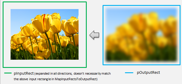
同様に、変換によって画像が縮小または展開される場合 (ここでのぼかしの例のように)、ピクセルは周囲のピクセルを使用して値を計算することがよくあります。 ぼかしを使用すると、入力画像の境界外にある場合でも、ピクセルは周囲のピクセルで平均化されます。 この動作は計算に反映されます。 前と同様に、変換は四角形の座標を展開するときにオーバーフローをチェックします。
// Expand the input rectangle to reflect that more pixels need to
// be read from than are necessarily rendered in the effect's output.
pInputRects[0].left   = ((pOutputRect->left   - 5) < pOutputRect->left  ) ? (pOutputRect->left   - 5) : LONG_MIN;
pInputRects[0].top    = ((pOutputRect->top    - 5) < pOutputRect->top   ) ? (pOutputRect->top    - 5) : LONG_MIN;
pInputRects[0].right  = ((pOutputRect->right  + 5) > pOutputRect->right ) ? (pOutputRect->right  + 5) : LONG_MAX;
pInputRects[0].bottom = ((pOutputRect->bottom + 5) > pOutputRect->bottom) ? (pOutputRect->bottom + 5) : LONG_MAX;
この図は、計算を視覚化します。 Direct2D は、入力画像が存在しない透明な黒ピクセルを自動的にサンプリングし、ぼかしを画面上の既存のコンテンツと徐々にブレンドできるようにします。
マッピングが単純でない場合は、正しい結果を保証するために、このメソッドは入力四角形を最大領域に設定する必要があります。 これを行うには、左端と上端をINT_MINに設定し、右端と下端をINT_MAXに設定します。
このメソッドの詳細については、「 MapOutputRectToInputRects 」トピックを参照してください。
MapInvalidRect
Direct2D は MapInvalidRect メソッドも呼び出します。 ただし、 MapInputRectsToOutputRect メソッドと MapOutputRectToInputRects メソッドとは異なり、Direct2D は特定の時点で呼び出す保証はありません。 このメソッドは、入力の変更の一部または全部に応じて、変換の出力の一部を再レンダリングする必要がある部分を概念的に決定します。 変換の無効な rect を計算する 3 つの異なるシナリオがあります。
1 対 1 のピクセル マッピングを使用した変換
ピクセル 1 から 1 をマップする変換の場合は、無効な入力四角形を無効な出力四角形に渡すだけです。
IFACEMETHODIMP SampleTransform::MapInvalidRect(
    UINT32 inputIndex,
    D2D1_RECT_L invalidInputRect,
    _Out_ D2D1_RECT_L* pInvalidOutputRect
    ) const
{
    // This transform is designed to only accept one input.
    if (inputIndex != 0)
    {
        return E_INVALIDARG;
    }

    // If part of the transform's input is invalid, mark the corresponding
    // output region as invalid.
    *pInvalidOutputRect = invalidInputRect;

    return S_OK;
}
多対多ピクセル マッピングを使用した変換
変換の出力ピクセルが周囲の領域に依存している場合は、無効な入力四角形をそれに対応して展開する必要があります。 これは、無効な入力四角形を囲むピクセルも影響を受け、無効になることを反映するためです。 たとえば、5 ピクセルのぼかしでは、次の計算が使用されます。
// Expand the input invalid rectangle by five pixels in each direction. This
// reflects that a change in part of the given input image will cause a change
// in an expanded part of the output image (five pixels in each direction).
pInvalidOutputRect->left   = ((invalidInputRect.left   - 5) < invalidInputRect.left  ) ? (invalidInputRect.left   - 5) : LONG_MIN;
pInvalidOutputRect->top    = ((invalidInputRect.top    - 5) < invalidInputRect.top   ) ? (invalidInputRect.top    - 5) : LONG_MIN;
pInvalidOutputRect->right  = ((invalidInputRect.right  + 5) > invalidInputRect.right ) ? (invalidInputRect.right  + 5) : LONG_MAX;
pInvalidOutputRect->bottom = ((invalidInputRect.bottom + 5) > invalidInputRect.bottom) ? (invalidInputRect.bottom + 5) : LONG_MAX;
複雑なピクセル マッピングを使用した変換
入力ピクセルと出力ピクセルに単純なマッピングがない変換の場合、出力全体が無効としてマークされる可能性があります。 たとえば、変換によって入力の平均色が出力されるだけの場合、入力の一部が変更されても、変換の出力全体が変わります。 この場合、無効な出力四角形は、論理的に無限の四角形 (以下に示す) に設定する必要があります。 Direct2D は 、これを出力の境界に自動的にクランプします。
// If any change in the input image affects the entire output, the
// transform should set pInvalidOutputRect to a logically infinite rect.
*pInvalidOutputRect = D2D1::RectL(LONG_MIN, LONG_MIN, LONG_MAX, LONG_MAX);
このメソッドの詳細については、「 MapInvalidRect 」トピックを参照してください。
これらのメソッドが実装されると、変換のヘッダーには次のものが含まれます。
class SampleTransform : public ID2D1Transform
{
public:
    SampleTransform();

    // ID2D1TransformNode Methods:
    IFACEMETHODIMP_(UINT32) GetInputCount() const;

    // ID2D1Transform Methods:
    IFACEMETHODIMP MapInputRectsToOutputRect(
        _In_reads_(inputRectCount) const D2D1_RECT_L* pInputRects,
        _In_reads_(inputRectCount) const D2D1_RECT_L* pInputOpaqueSubRects,
        UINT32 inputRectCount,
        _Out_ D2D1_RECT_L* pOutputRect,
        _Out_ D2D1_RECT_L* pOutputOpaqueSubRect
        );

    IFACEMETHODIMP MapOutputRectToInputRects(
        _In_ const D2D1_RECT_L* pOutputRect,
        _Out_writes_(inputRectCount) D2D1_RECT_L* pInputRects,
        UINT32 inputRectCount
        ) const;

    IFACEMETHODIMP MapInvalidRect(
        UINT32 inputIndex,
        D2D1_RECT_L invalidInputRect,
        _Out_ D2D1_RECT_L* pInvalidOutputRect
        ) const;

    // IUnknown Methods:
    IFACEMETHODIMP_(ULONG) AddRef();
    IFACEMETHODIMP_(ULONG) Release();
    IFACEMETHODIMP QueryInterface(REFIID riid, _Outptr_ void** ppOutput);

private:
    LONG m_cRef; // Internal ref count used by AddRef() and Release() methods.
    D2D1_RECT_L m_inputRect; // Stores the size of the input image.
};
カスタム変換へのピクセル シェーダーの追加
変換が作成されたら、イメージ ピクセルを操作するシェーダーを提供する必要があります。 このセクションでは、カスタム変換でピクセル シェーダーを使用する手順について説明します。
ID2D1DrawTransform の実装
ピクセル シェーダーを使用するには、変換で ID2D1DrawTransform インターフェイスを実装する必要があります。これは、セクション 5 で説明されている ID2D1Transform インターフェイスから継承されます。 このインターフェイスには、実装する新しいメソッドが 1 つ含まれています。
SetDrawInfo(ID2D1DrawInfo *pDrawInfo)
Direct2D は、変換が最初にエフェクトの変換グラフに追加されるときに SetDrawInfo メソッドを呼び出します。 このメソッドは、変換のレンダリング方法を制御する ID2D1DrawInfo パラメーターを提供します。 ここで使用できるメソッドについては、 ID2D1DrawInfo に関するトピックを参照してください。
変換でこのパラメーターをクラス メンバー変数として格納することを選択した場合、 drawInfo オブジェクトにアクセスして、プロパティ セッターや MapInputRectsToOutputRect などの他のメソッドから変更できます。 特に、ID2D1Transform の MapOutputRectToInputRects メソッドまたは MapInvalidRect メソッドから呼び出すことはできません。
ピクセル シェーダーの GUID の作成
次に、ピクセル シェーダー自体の一意の GUID を変換で定義する必要があります。 これは、 Direct2D がシェーダーをメモリに読み込む場合や、変換で実行に使用するピクセル シェーダーを選択するときに使用されます。 Visual Studio に含まれている guidgen.exe などのツールを使用して、ランダムな GUID を生成できます。
// Example GUID used to uniquely identify HLSL shader. Passed to Direct2D during
// shader load, and used by the transform to identify the shader for the
// ID2D1DrawInfo::SetPixelShader method. The effect author should create a
// unique name for the shader as well as a unique GUID using
// a GUID generation tool.
DEFINE_GUID(GUID_SamplePixelShader, 0x00000000, 0x0000, 0x0000, 0x00, 0x00, 0x00, 0x00, 0x00, 0x00, 0x00, 0x00);
Direct2D を使用したピクセル シェーダーの読み込み
ピクセル シェーダーは、変換で使用する前にメモリに読み込む必要があります。
ピクセル シェーダーをメモリに読み込むには、 からコンパイルされたシェーダー バイト コードを変換で読み取る必要があります。Visual Studio によって生成された CSO ファイル (詳細については 、Direct3D ドキュメントを参照) をバイト配列に格納します。 この手法の詳細については、 D2DCustomEffects SDK サンプルを参照してください。
シェーダー データがバイト配列に読み込まれたら、効果の ID2D1EffectContext オブジェクトに対して LoadPixelShader メソッドを呼び出します。 同じ GUID を持つシェーダーが既に読み込まれている場合、Direct2D は LoadPixelShader の呼び出しを無視します。
ピクセル シェーダーがメモリに読み込まれた後、変換では、SetDrawInfo メソッドの間に指定された ID2D1DrawInfo パラメーターの SetPixelShader メソッドに GUID を渡して、実行のためにそれを選択する必要があります。 ピクセル シェーダーは、実行のために選択される前に、メモリに既に読み込まれている必要があります。
定数バッファーを使用したシェーダー操作の変更
シェーダーの実行方法を変更するために、変換によって定数バッファーがピクセル シェーダーに渡される場合があります。 これを行うには、変換によって、クラス ヘッダーに目的の変数を含む構造体が定義されます。
// This struct defines the constant buffer of the pixel shader.
struct
{
    float valueOne;
    float valueTwo;
} m_constantBuffer;
次に、SetDrawInfo メソッドで指定された ID2D1DrawInfo パラメーターで ID2D1DrawInfo::SetPixelShaderConstantBuffer メソッドを呼び出して、このバッファーをシェーダーに渡します。
HLSL では、定数バッファーを表す対応する構造体も定義する必要があります。 シェーダーの構造体に含まれる変数は、変換の構造体の変数と一致する必要があります。
cbuffer constants : register(b0)
{
    float valueOne : packoffset(c0.x);
    float valueTwo : packoffset(c0.y);
};
バッファーが定義されると、 内に含まれる値をピクセル シェーダー内の任意の場所から読み取ることができます。
Direct2D 用のピクセル シェーダーの作成
Direct2D 変換では、標準 HLSL を使用して作成されたシェーダーが使用されます。 ただし、変換のコンテキストから実行されるピクセル シェーダーを記述するには、いくつかの重要な概念があります。 完全に機能するピクセル シェーダーの完成した例については、 D2DCustomEffects SDK サンプルを参照してください。
Direct2D は 、変換の入力を HLSL の Texture2D オブジェクトと SamplerState オブジェクトに自動的にマップします。 最初の Texture2D はレジスタ t0 にあり、最初の SamplerState はレジスタ s0 にあります。 追加の各入力は、次の対応するレジスタ (t1 や s1 など) にあります。 Texture2D オブジェクトで Sample を呼び出し、対応する SamplerState オブジェクトとテクセル座標を渡すことで、特定の入力のピクセル データをサンプリングできます。
カスタム ピクセル シェーダーは、レンダリングされるピクセルごとに 1 回実行されます。 シェーダーが実行されるたびに、 Direct2D は現在の実行位置を識別する 3 つのパラメーターを自動的に提供します。
- シーン空間出力: このパラメーターは、ターゲット サーフェス全体の現在の実行位置を表します。 これはピクセル単位で定義され、最小値/最大値は MapInputRectsToOutputRect によって返される四角形の境界に対応します。
- クリップスペース出力: このパラメーターは Direct3D で使用され、変換のピクセル シェーダーでは使用できません。
- テクセル空間入力: このパラメーターは、特定の入力テクスチャ内の現在の実行位置を表します。 シェーダーは、この値の計算方法に依存しないようにする必要があります。 次のコードに示すように、ピクセル シェーダーの入力をサンプリングするためにのみ使用する必要があります。
Texture2D InputTexture : register(t0);
SamplerState InputSampler : register(s0);

float4 main(
    float4 clipSpaceOutput  : SV_POSITION,
    float4 sceneSpaceOutput : SCENE_POSITION,
    float4 texelSpaceInput0 : TEXCOORD0
    ) : SV_Target
{
    // Samples pixel from ten pixels above current position.

    float2 sampleLocation =
        texelSpaceInput0.xy    // Sample position for the current output pixel.
        + float2(0,-10)        // An offset from which to sample the input, specified in pixels.
        * texelSpaceInput0.zw; // Multiplier that converts pixel offset to sample position offset.

    float4 color = InputTexture.Sample(
        InputSampler,          // Sampler and Texture must match for a given input.
        sampleLocation
        );

    return color;
}
頂点シェーダーをカスタム変換に追加する
頂点シェーダーを使用して、ピクセル シェーダーとは異なるイメージング シナリオを実現できます。 特に、頂点シェーダーは、イメージを構成する頂点を変換することで、ジオメトリベースのイメージ効果を実行できます。 頂点シェーダーは、変換指定ピクセル シェーダーとは独立して使用することも、変換指定のピクセル シェーダーと組み合わせて使用することもできます。 頂点シェーダーが指定されていない場合、 Direct2D はカスタム ピクセル シェーダーで使用するために既定の頂点シェーダーに置き換えます。
カスタム変換に頂点シェーダーを追加するプロセスは、ピクセル シェーダーのプロセスと似ています。変換では ID2D1DrawTransform インターフェイスが実装され、GUID が作成され、(必要に応じて) 定数バッファーがシェーダーに渡されます。 ただし、頂点シェーダーに固有の重要な追加手順がいくつかあります。
頂点バッファーの作成
定義による頂点シェーダーは、個々のピクセルではなく、渡された頂点に対して実行されます。 シェーダーを実行する頂点を指定するために、シェーダーに渡す頂点バッファーが変換によって作成されます。 頂点バッファーのレイアウトは、このドキュメントの範囲外です。 詳細については Direct3D リファレンスを参照 するか、サンプル実装の D2DCustomEffects SDK サンプル を参照してください。
メモリに頂点バッファーを作成した後、変換では、含まれているエフェクトの ID2D1EffectContext オブジェクトで CreateVertexBuffer メソッドを使用して、そのデータを GPU に渡します。 ここでも、サンプル実装については 、D2DCustomEffects SDK サンプル を参照してください。
変換で頂点バッファーが指定されていない場合、 Direct2D は四角形のイメージの位置を表す既定の頂点バッファーを渡します。
頂点シェーダーを利用するように SetDrawInfo を変更する
ピクセル シェーダーと同様に、変換では、実行する頂点シェーダーを読み込んで選択する必要があります。 頂点シェーダーを読み込むには、エフェクトの Initialize メソッドで受け取った ID2D1EffectContext メソッドで LoadVertexShader メソッドを呼び出します。 実行する頂点シェーダーを選択するには、変換の SetDrawInfo メソッドで受け取った ID2D1DrawInfo パラメーターで SetVertexProcessing を呼び出します。 このメソッドは、以前に読み込まれた頂点シェーダーの GUID と、(必要に応じて) シェーダーを実行するために以前に作成した頂点バッファーを受け入れます。
Direct2D 頂点シェーダーの実装
描画変換には、ピクセル シェーダーと頂点シェーダーの両方を含めることができます。 変換でピクセル シェーダーと頂点シェーダーの両方が定義されている場合、頂点シェーダーからの出力はピクセル シェーダーに直接渡されます。アプリでは、一貫性がある限り、頂点シェーダーの戻り値シグネチャ/ピクセル シェーダーのパラメーターをカスタマイズできます。
一方、変換に頂点シェーダーのみが含まれており、 Direct2D の既定のパススルー ピクセル シェーダーに依存している場合は、次の既定の出力を返す必要があります。
struct VSOut
{
    float4 clipSpaceOutput  : SV_POSITION;
    float4 sceneSpaceOutput : SCENE_POSITION;
    float4 texelSpaceInput0 : TEXCOORD0;
};
頂点シェーダーは、その頂点変換の結果をシェーダーの Scene-space 出力変数に格納します。 クリップスペース出力とテクセル空間入力変数を計算するために、 Direct2D は定数バッファーに変換行列を自動的に提供します。
// Constant buffer b0 is used to store the transformation matrices from scene space
// to clip space. Depending on the number of inputs to the vertex shader, there
// may be more or fewer "sceneToInput" matrices.
cbuffer Direct2DTransforms : register(b0)
{
    float2x1 sceneToOutputX;
    float2x1 sceneToOutputY;
    float2x1 sceneToInput0X;
    float2x1 sceneToInput0Y;
};
Direct2D で想定される正しいクリップとテクセル空間を計算するために変換マトリックスを使用する頂点シェーダー コードのサンプルを次に示します。
// Constant buffer b0 is used to store the transformation matrices from scene space
// to clip space. Depending on the number of inputs to the vertex shader, there
// may be more or fewer "sceneToInput" matrices.
cbuffer Direct2DTransforms : register(b0)
{
    float2x1 sceneToOutputX;
    float2x1 sceneToOutputY;
    float2x1 sceneToInput0X;
    float2x1 sceneToInput0Y;
};

// Default output structure. This can be customized if transform also contains pixel shader.
struct VSOut
{
    float4 clipSpaceOutput  : SV_POSITION;
    float4 sceneSpaceOutput : SCENE_POSITION;
    float4 texelSpaceInput0 : TEXCOORD0;
};

// The parameter(s) passed to the vertex shader are defined by the vertex buffer's layout
// as specified by the transform. If no vertex buffer is specified, Direct2D passes two
// triangles representing the rectangular image with the following layout:
//
//    float4 outputScenePosition : OUTPUT_SCENE_POSITION;
//
//    The x and y coordinates of the outputScenePosition variable represent the image's
//    position on the screen. The z and w coordinates are used for perspective and
//    depth-buffering.

VSOut GeometryVS(float4 outputScenePosition : OUTPUT_SCENE_POSITION)
{
    VSOut output;

    // Compute Scene-space output (vertex simply passed-through here).
    output.sceneSpaceOutput.x = outputScenePosition.x;
    output.sceneSpaceOutput.y = outputScenePosition.y;
    output.sceneSpaceOutput.z = outputScenePosition.z;
    output.sceneSpaceOutput.w = outputScenePosition.w;

    // Generate standard Clip-space output coordinates.
    output.clipSpaceOutput.x = (output.sceneSpaceOutput.x * sceneToOutputX[0]) +
        output.sceneSpaceOutput.w * sceneToOutputX[1];

    output.clipSpaceOutput.y = (output.sceneSpaceOutput.y * sceneToOutputY[0]) +
        output.sceneSpaceOutput.w * sceneToOutputY[1];

    output.clipSpaceOutput.z = output.sceneSpaceOutput.z;
    output.clipSpaceOutput.w = output.sceneSpaceOutput.w;

    // Generate standard Texel-space input coordinates.
    output.texelSpaceInput0.x = (outputScenePosition.x * sceneToInput0X[0]) + sceneToInput0X[1];
    output.texelSpaceInput0.y = (outputScenePosition.y * sceneToInput0Y[0]) + sceneToInput0Y[1];
    output.texelSpaceInput0.z = sceneToInput0X[0];
    output.texelSpaceInput0.w = sceneToInput0Y[0];

    return output;
}
上記のコードは、頂点シェーダーの開始点として使用できます。 変換を実行せずに入力イメージを通過するだけです。 ここでも、完全に実装された頂点シェーダーベースの変換については、 D2DCustomEffects SDK サンプル を参照してください。
変換で頂点バッファーが指定されていない場合、 Direct2D は四角形のイメージの位置を表す既定の頂点バッファーに置き換えられます。 頂点シェーダーのパラメーターは、既定のシェーダー出力に変更されます。
struct VSIn
{
    float4 clipSpaceOutput  : SV_POSITION;
    float4 sceneSpaceOutput : SCENE_POSITION;
    float4 texelSpaceInput0 : TEXCOORD0;
};
頂点シェーダーでは、sceneSpaceOutput パラメーターと clipSpaceOutput パラメーターを変更することはできません。 変更せずに返す必要があります。 ただし、入力イメージごとに texelSpaceInput パラメーターを変更できます。 変換にカスタム ピクセル シェーダーも含まれている場合でも、頂点シェーダーは追加のカスタム パラメーターをピクセル シェーダーに直接渡すことができます。 さらに、 sceneSpace 変換マトリックスのカスタム バッファー (b0) は提供されなくなりました。
カスタム変換へのコンピューティング シェーダーの追加
最後に、カスタム変換では、特定の対象となるシナリオにコンピューティング シェーダーを利用できます。 コンピューティング シェーダーを使用すると、入力および出力イメージ バッファーへの任意のアクセスを必要とする複雑なイメージ効果を実装できます。 たとえば、メモリ アクセスの制限により、基本的なヒストグラム アルゴリズムをピクセル シェーダーで実装することはできません。
コンピューティング シェーダーにはピクセル シェーダーよりも高いハードウェア機能レベルの要件があるため、可能な場合はピクセル シェーダーを使用して特定の効果を実装する必要があります。 具体的には、コンピューティング シェーダーは、ほとんどの DirectX 10 レベル カード以降でのみ実行されます。 変換でコンピューティング シェーダーの使用を選択した場合は、ID2D1ComputeTransform インターフェイスの実装に加えて、インスタンス化中に適切なハードウェア サポートに対してチェックする必要があります。
コンピューティング シェーダーのサポートの確認
効果でコンピューティング シェーダーを使用する場合は、ID2D1EffectContext::CheckFeatureSupport メソッドを使用して、作成時にコンピューティング シェーダーのサポートにチェックする必要があります。 GPU がコンピューティング シェーダーをサポートしていない場合、効果は D2DERR_INSUFFICIENT_DEVICE_CAPABILITIESを返す必要があります。
変換で使用できるコンピューティング シェーダーには、シェーダー モデル 4 (DirectX 10) とシェーダー モデル 5 (DirectX 11) の 2 種類があります。 シェーダー モデル 4 シェーダーには特定の制限があります。 詳細については、 Direct3D のドキュメントを参照してください。 変換には両方の種類のシェーダーを含めることができます。また、必要に応じてシェーダー モデル 4 にフォールバックすることもできます。この実装については 、D2DCustomEffects SDK サンプル を参照してください。
ID2D1ComputeTransform を実装する
このインターフェイスには、 ID2D1Transform のメソッドに加えて、実装する 2 つの新しいメソッドが含まれています。
SetComputeInfo(ID2D1ComputeInfo *pComputeInfo)
ピクセル シェーダーや頂点シェーダーと同様に、 Direct2D は、変換がエフェクトの変換グラフに最初に追加されるときに SetComputeInfo メソッドを呼び出します。 このメソッドは、変換のレンダリング方法を制御する ID2D1ComputeInfo パラメーターを提供します。 これには、 ID2D1ComputeInfo::SetComputeShader メソッドを使用して実行するコンピューティング シェーダーの選択が含まれます。 変換でこのパラメーターをクラス メンバー変数として格納することを選択した場合は、 MapOutputRectToInputRects メソッドと MapInvalidRect メソッドを除き、任意の変換または効果メソッドからアクセスおよび変更できます。 ここで使用できるその他のメソッドについては、 ID2D1ComputeInfo に関するトピックを参照してください。
CalculateThreadgroups(const D2D1_RECT_L *pOutputRect, UINT32 *pDimensionX, UINT32 *pDimensionY, UINT32 *pDimensionZ)
ピクセル シェーダーはピクセル単位で実行され、頂点シェーダーは頂点ごとに実行されますが、コンピューティング シェーダーはスレッド グループごとに実行されます。 スレッド グループは、GPU で同時に実行されるスレッドの数を表します。 コンピューティング シェーダー HLSL コードは、スレッド グループごとに実行するスレッドの数を決定します。 効果は、シェーダーのロジックに応じて、シェーダーが必要な回数だけ実行されるようにスレッド グループの数をスケーリングします。
CalculateThreadgroups メソッドを使用すると、イメージのサイズとシェーダーに関する変換独自の知識に基づいて、必要なスレッド グループの数を Direct2D に通知できます。
コンピューティング シェーダーが実行される回数は、ここで指定したスレッド グループ数と、コンピューティング シェーダー HLSL の 'numthreads' 注釈の積です。 たとえば、変換によってスレッド グループのディメンションが (2,2,1) に設定され、シェーダーでスレッド グループごとに (3,3,1) スレッドが指定されている場合、スレッド グループは 4 つ実行され、スレッド グループはそれぞれ 9 スレッドで合計 36 スレッド インスタンスになります。
一般的なシナリオでは、コンピューティング シェーダーのインスタンスごとに 1 つの出力ピクセルを処理します。 このシナリオのスレッド グループの数を計算するために、変換によって、イメージの幅と高さが、コンピューティング シェーダー HLSL の 'numthreads' 注釈のそれぞれの x 次元と y 次元で除算されます。
重要なのは、この除算が実行される場合、要求されたスレッド グループの数は常に最も近い整数に切り上げる必要があります。そうしないと、'剰余' ピクセルは実行されません。 シェーダー (たとえば) が各スレッドで 1 ピクセルを計算すると、メソッドのコードは次のように表示されます。
IFACEMETHODIMP SampleTransform::CalculateThreadgroups(
    _In_ const D2D1_RECT_L* pOutputRect,
    _Out_ UINT32* pDimensionX,
    _Out_ UINT32* pDimensionY,
    _Out_ UINT32* pDimensionZ
    )
{
    // The input image's dimensions are divided by the corresponding number of threads in each
    // threadgroup. This is specified in the HLSL, and in this example is 24 for both the x and y
    // dimensions. Dividing the image dimensions by these values calculates the number of
    // thread groups that need to be executed.

    *pDimensionX = static_cast<UINT32>(
         ceil((m_inputRect.right - m_inputRect.left) / 24.0f);

    *pDimensionY = static_cast<UINT32>(
         ceil((m_inputRect.bottom - m_inputRect.top) / 24.0f);

    // The z dimension is set to '1' in this example because the shader will
    // only be executed once for each pixel in the two-dimensional input image.
    // This value can be increased to perform additional executions for a given
    // input position.
    *pDimensionZ = 1;

    return S_OK;
}
HLSL では、次のコードを使用して、各スレッド グループ内のスレッド数を指定します。
// numthreads(x, y, z)
// This specifies the number of threads in each dispatched threadgroup.
// For Shader Model 4, z == 1 and x*y*z <= 768. For Shader Model 5, z <= 64 and x*y*z <= 1024.
[numthreads(24, 24, 1)]
void main(
...
実行中に、現在のスレッド グループと現在のスレッド インデックスがシェーダー メソッドにパラメーターとして渡されます。
#define NUMTHREADS_X 24
#define NUMTHREADS_Y 24

// numthreads(x, y, z)
// This specifies the number of threads in each dispatched threadgroup.
// For Shader Model 4, z == 1 and x*y*z <= 768. For Shader Model 5, z <= 64 and x*y*z <= 1024.
[numthreads(NUMTHREADS_X, NUMTHREADS_Y, 1)]
void main(
    // dispatchThreadId - Uniquely identifies a given execution of the shader, most commonly used parameter.
    // Definition: (groupId.x * NUM_THREADS_X + groupThreadId.x, groupId.y * NUMTHREADS_Y + groupThreadId.y,
    // groupId.z * NUMTHREADS_Z + groupThreadId.z)
    uint3 dispatchThreadId  : SV_DispatchThreadID,

    // groupThreadId - Identifies an individual thread within a thread group.
    // Range: (0 to NUMTHREADS_X - 1, 0 to NUMTHREADS_Y - 1, 0 to NUMTHREADS_Z - 1)
    uint3 groupThreadId     : SV_GroupThreadID,

    // groupId - Identifies which thread group the individual thread is being executed in.
    // Range defined in ID2D1ComputeTransform::CalculateThreadgroups.
    uint3 groupId           : SV_GroupID,

    // One dimensional indentifier of a compute shader thread within a thread group.
    // Range: (0 to NUMTHREADS_X * NUMTHREADS_Y * NUMTHREADS_Z - 1)
    uint  groupIndex        : SV_GroupIndex
    )
{
...
画像データの読み取り
コンピューティング シェーダーは、変換の入力イメージに 1 つの 2 次元テクスチャとしてアクセスします。
Texture2D<float4> InputTexture : register(t0);
SamplerState InputSampler : register(s0);
ただし、ピクセル シェーダーと同様に、イメージのデータはテクスチャの (0, 0) から始まる保証はありません。 代わりに、 Direct2D には、シェーダーがオフセットを補正できるシステム定数が用意されています。
// These are default constants passed by D2D.
cbuffer systemConstants : register(b0)
{
    int4 resultRect; // Represents the input rectangle to the shader in terms of pixels.
    float2 sceneToInput0X;
    float2 sceneToInput0Y;
};

// The image does not necessarily begin at (0,0) on InputTexture. The shader needs
// to use the coefficients provided by Direct2D to map the requested image data to
// where it resides on the texture.
float2 ConvertInput0SceneToTexelSpace(float2 inputScenePosition)
{
    float2 ret;
    ret.x = inputScenePosition.x * sceneToInput0X[0] + sceneToInput0X[1];
    ret.y = inputScenePosition.y * sceneToInput0Y[0] + sceneToInput0Y[1];

    return ret;
}
上記の定数バッファーとヘルパー メソッドが定義されると、シェーダーは次を使用して画像データをサンプリングできます。
float4 color = InputTexture.SampleLevel(
        InputSampler,
        ConvertInput0SceneToTexelSpace(
            float2(xIndex + .5, yIndex + .5) + // Add 0.5 to each coordinate to hit the center of the pixel.
            resultRect.xy // Offset sampling location by input image offset.
            ),
        0
        );
画像データの書き込み
Direct2D では、シェーダーが、結果のイメージを配置するための出力バッファーを定義することを想定しています。 シェーダー モデル 4 (DirectX 10) では、特徴の制約により、これは 1 次元バッファーである必要があります。
// Shader Model 4 does not support RWTexture2D, must use 1D buffer instead.
RWStructuredBuffer<float4> OutputTexture : register(t1);
出力テクスチャは、イメージ全体を格納できるように、行優先でインデックスが付けられます。
uint imageWidth = resultRect[2] - resultRect[0];
uint imageHeight = resultRect[3] - resultRect[1];
OutputTexture[yIndex * imageWidth + xIndex] = color;
一方、シェーダー モデル 5 (DirectX 11) シェーダーでは、2 次元出力テクスチャを使用できます。
RWTexture2D<float4> OutputTexture : register(t1);
シェーダー モデル 5 シェーダーでは、 Direct2D は定数バッファーに追加の 'outputOffset' パラメーターを提供します。 シェーダーの出力は、次の量だけオフセットする必要があります。
OutputTexture[uint2(xIndex, yIndex) + outputOffset.xy] = color;
完成したパススルー シェーダー モデル 5 コンピューティング シェーダーを次に示します。 その中で、各コンピューティング シェーダー スレッドは、入力イメージの 1 ピクセルを読み取り、書き込みます。
#define NUMTHREADS_X 24
#define NUMTHREADS_Y 24

Texture2D<float4> InputTexture : register(t0);
SamplerState InputSampler : register(s0);

RWTexture2D<float4> OutputTexture : register(t1);

// These are default constants passed by D2D.
cbuffer systemConstants : register(b0)
{
    int4 resultRect; // Represents the region of the output image.
    int2 outputOffset;
    float2 sceneToInput0X;
    float2 sceneToInput0Y;
};

// The image does not necessarily begin at (0,0) on InputTexture. The shader needs
// to use the coefficients provided by Direct2D to map the requested image data to
// where it resides on the texture.
float2 ConvertInput0SceneToTexelSpace(float2 inputScenePosition)
{
    float2 ret;
    ret.x = inputScenePosition.x * sceneToInput0X[0] + sceneToInput0X[1];
    ret.y = inputScenePosition.y * sceneToInput0Y[0] + sceneToInput0Y[1];

    return ret;
}

// numthreads(x, y, z)
// This specifies the number of threads in each dispatched threadgroup.
// For Shader Model 5, z <= 64 and x*y*z <= 1024
[numthreads(NUMTHREADS_X, NUMTHREADS_Y, 1)]
void main(
    // dispatchThreadId - Uniquely identifies a given execution of the shader, most commonly used parameter.
    // Definition: (groupId.x * NUM_THREADS_X + groupThreadId.x, groupId.y * NUMTHREADS_Y + groupThreadId.y,
    // groupId.z * NUMTHREADS_Z + groupThreadId.z)
    uint3 dispatchThreadId  : SV_DispatchThreadID,

    // groupThreadId - Identifies an individual thread within a thread group.
    // Range: (0 to NUMTHREADS_X - 1, 0 to NUMTHREADS_Y - 1, 0 to NUMTHREADS_Z - 1)
    uint3 groupThreadId     : SV_GroupThreadID,

    // groupId - Identifies which thread group the individual thread is being executed in.
    // Range defined in DFTVerticalTransform::CalculateThreadgroups.
    uint3 groupId           : SV_GroupID,

    // One dimensional indentifier of a compute shader thread within a thread group.
    // Range: (0 to NUMTHREADS_X * NUMTHREADS_Y * NUMTHREADS_Z - 1)
    uint  groupIndex        : SV_GroupIndex
    )
{
    uint xIndex = dispatchThreadId.x;
    uint yIndex = dispatchThreadId.y;

    uint imageWidth = resultRect.z - resultRect.x;
    uint imageHeight = resultRect.w - resultRect.y;

    // It is likely that the compute shader will execute beyond the bounds of the input image, since the shader is
    // executed in chunks sized by the threadgroup size defined in ID2D1ComputeTransform::CalculateThreadgroups.
    // For this reason each shader should ensure the current dispatchThreadId is within the bounds of the input
    // image before proceeding.
    if (xIndex >= imageWidth || yIndex >= imageHeight)
    {
        return;
    }

    float4 color = InputTexture.SampleLevel(
        InputSampler,
        ConvertInput0SceneToTexelSpace(
            float2(xIndex + .5, yIndex + .5) + // Add 0.5 to each coordinate to hit the center of the pixel.
            resultRect.xy // Offset sampling location by image offset.
            ),
        0
        );

    OutputTexture[uint2(xIndex, yIndex) + outputOffset.xy] = color;
次のコードは、シェーダーの同等のシェーダー モデル 4 バージョンを示しています。 シェーダーが 1 次元出力バッファーにレンダリングされるようになりました。
#define NUMTHREADS_X 24
#define NUMTHREADS_Y 24

Texture2D<float4> InputTexture : register(t0);
SamplerState InputSampler : register(s0);

// Shader Model 4 does not support RWTexture2D, must use one-dimensional buffer instead.
RWStructuredBuffer<float4> OutputTexture : register(t1);

// These are default constants passed by D2D. See PixelShader and VertexShader
// projects for how to pass custom values into a shader.
cbuffer systemConstants : register(b0)
{
    int4 resultRect; // Represents the region of the output image.
    float2 sceneToInput0X;
    float2 sceneToInput0Y;
};

// The image does not necessarily begin at (0,0) on InputTexture. The shader needs
// to use the coefficients provided by Direct2D to map the requested image data to
// where it resides on the texture.
float2 ConvertInput0SceneToTexelSpace(float2 inputScenePosition)
{
    float2 ret;
    ret.x = inputScenePosition.x * sceneToInput0X[0] + sceneToInput0X[1];
    ret.y = inputScenePosition.y * sceneToInput0Y[0] + sceneToInput0Y[1];

    return ret;
}

// numthreads(x, y, z)
// This specifies the number of threads in each dispatched threadgroup.
// For Shader Model 4, z == 1 and x*y*z <= 768
[numthreads(NUMTHREADS_X, NUMTHREADS_Y, 1)]
void main(
    // dispatchThreadId - Uniquely identifies a given execution of the shader, most commonly used parameter.
    // Definition: (groupId.x * NUM_THREADS_X + groupThreadId.x, groupId.y * NUMTHREADS_Y + groupThreadId.y, groupId.z * NUMTHREADS_Z + groupThreadId.z)
    uint3 dispatchThreadId  : SV_DispatchThreadID,

    // groupThreadId - Identifies an individual thread within a thread group.
    // Range: (0 to NUMTHREADS_X - 1, 0 to NUMTHREADS_Y - 1, 0 to NUMTHREADS_Z - 1)
    uint3 groupThreadId     : SV_GroupThreadID,

    // groupId - Identifies which thread group the individual thread is being executed in.
    // Range defined in DFTVerticalTransform::CalculateThreadgroups
    uint3 groupId           : SV_GroupID,

    // One dimensional indentifier of a compute shader thread within a thread group.
    // Range: (0 to NUMTHREADS_X * NUMTHREADS_Y * NUMTHREADS_Z - 1)
    uint  groupIndex        : SV_GroupIndex
    )
{
    uint imageWidth = resultRect[2] - resultRect[0];
    uint imageHeight = resultRect[3] - resultRect[1];

    uint xIndex = dispatchThreadId.x;
    uint yIndex = dispatchThreadId.y;

    // It is likely that the compute shader will execute beyond the bounds of the input image, since the shader is executed in chunks sized by
    // the threadgroup size defined in ID2D1ComputeTransform::CalculateThreadgroups. For this reason each shader should ensure the current
    // dispatchThreadId is within the bounds of the input image before proceeding.
    if (xIndex >= imageWidth || yIndex >= imageHeight)
    {
        return;
    }

    float4 color = InputTexture.SampleLevel(
        InputSampler,
        ConvertInput0SceneToTexelSpace(
            float2(xIndex + .5, yIndex + .5) + // Add 0.5 to each coordinate to hit the center of the pixel.
            resultRect.xy // Offset sampling location by image offset.
            ),
        0
        );

    OutputTexture[yIndex * imageWidth + xIndex] = color;
}
関連トピック