Training
Certification
Microsoft Certified: Azure Virtual Desktop Specialty - Certifications
Plan, deliver, manage, and monitor virtual desktop experiences and remote apps on Microsoft Azure for any device.
This browser is no longer supported.
Upgrade to Microsoft Edge to take advantage of the latest features, security updates, and technical support.
Azure Digital Twins 3D Scenes Studio (preview) is an immersive 3D environment, where business and frontline workers can consume and investigate operational data from their Azure Digital Twins solutions with visual context.
In this article, you set up all the required resources for using 3D Scenes Studio, including an Azure Digital Twins instance with sample data, and Azure storage resources. Then, you create a scene in the studio that connects to the sample Azure Digital Twins environment.
This sample scene used in this quickstart monitors the carrying efficiency of robotic arms in a factory. The robotic arms pick up some boxes each hour, while video cameras monitor each of the arms to detect if the arm failed to pick up a box. Each arm has an associated digital twin in Azure Digital Twins, and the digital twins are updated with data whenever an arm misses a box. Given this scenario, this quickstart walks through setting up a 3D scene to visualize the arms in the factory, along with visual alerts each time a box is missed.
The scene looks like this:

You need an Azure subscription to complete this quickstart. If you don't have one already, create one for free now.
You also need to download a sample glTF (Graphics Language Transmission Format) 3D file to use for the scene in this quickstart. Download the following sample file from GitHub: RobotArms.glb.
The first step in working with Azure Digital Twins is to create an Azure Digital Twins instance. After you create an instance of the service, you can link the instance to a 3D Scenes Studio visualization later in the quickstart.
The rest of this section walks you through the instance creation. If you already have an Azure Digital Twins instance set up from an earlier quickstart, you can skip to the next section.
In this section, you create a new instance of Azure Digital Twins using the Azure portal. Navigate to the portal and sign in with your credentials.
Once in the portal, start by selecting Create a resource in the Azure services home page menu.
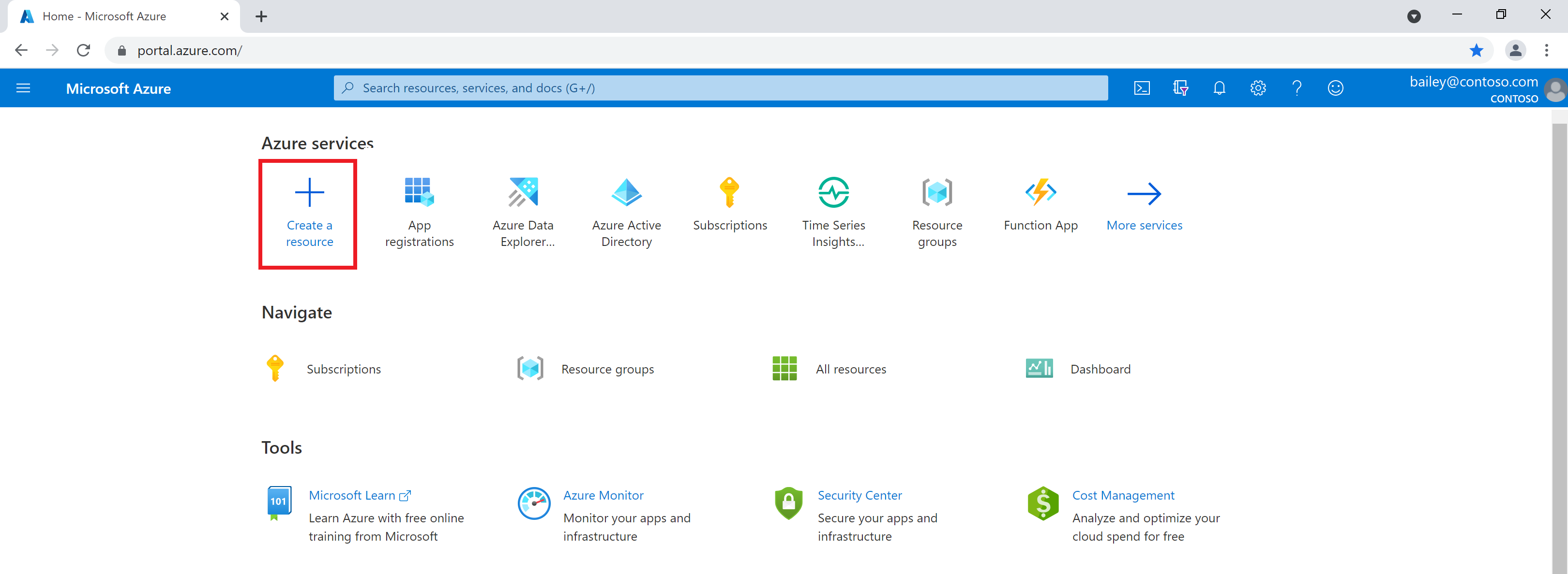
Search for Azure Digital Twins in the search box, and choose the Azure Digital Twins service from the results.
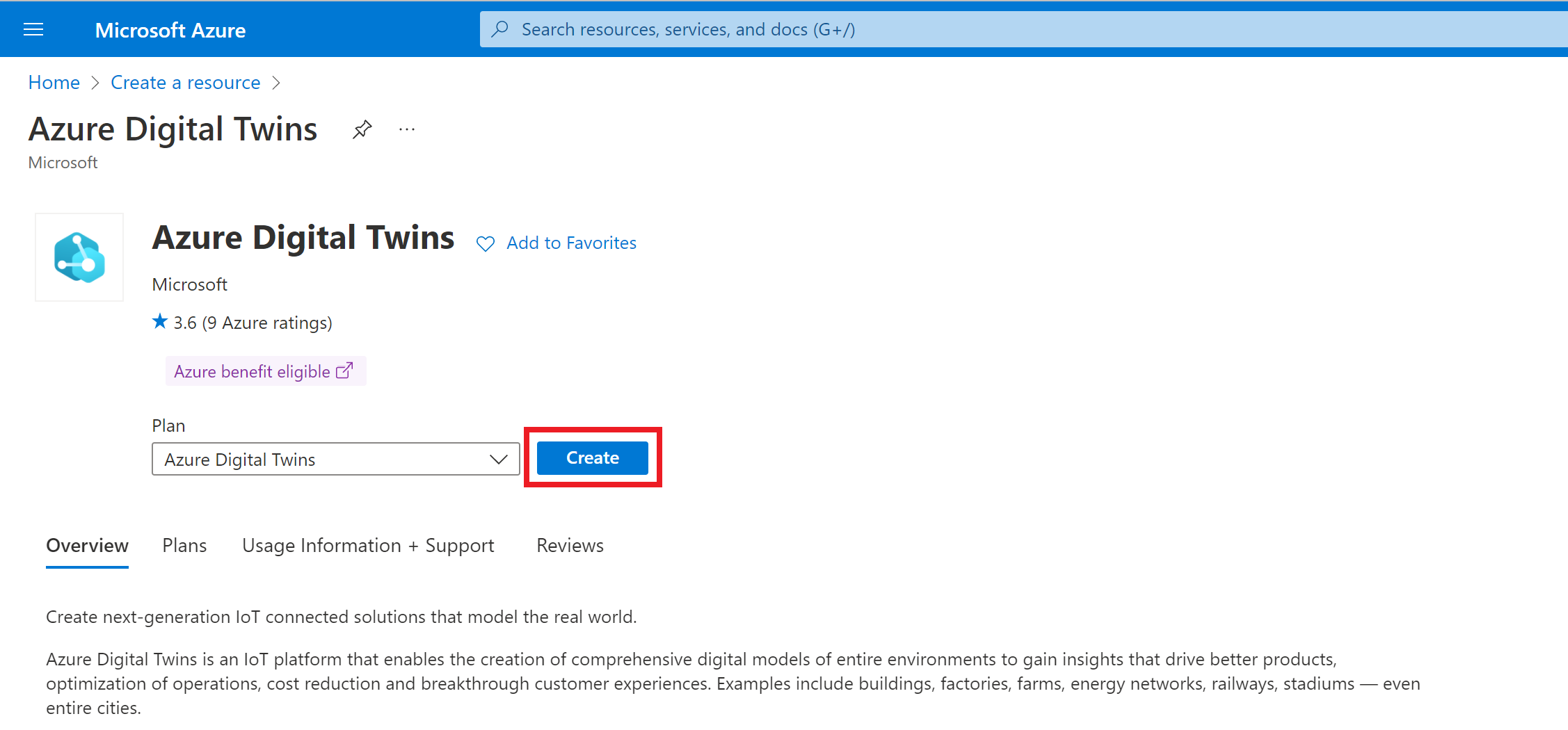
Leave the Plan field set to Azure Digital Twins and select the Create button to start creating a new instance of the service.
Fill in the fields on the Basics tab of setup, including your subscription, resource group, a resource name for your new instance, and region. Check the Assign Azure Digital Twins Data Owner Role box to give yourself permissions to manage data in the instance.
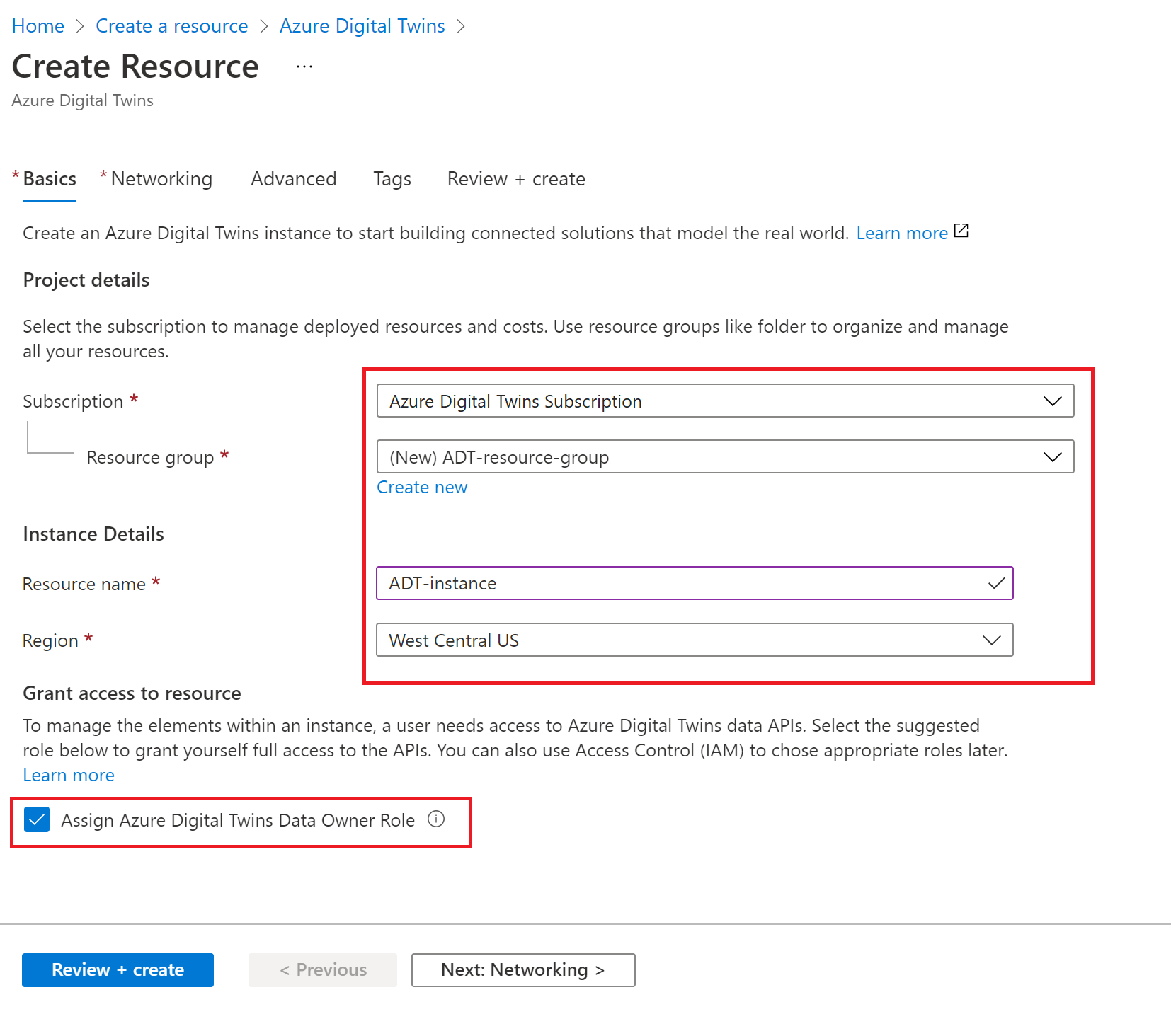
Note
If the Assign Azure Digital Twins Data Owner Role box is greyed out, it means you don't have permissions in your Azure subscription to manage user access to resources. You can continue creating the instance in this section, and then should have someone with the necessary permissions assign you this role on the instance before completing the rest of this quickstart.
Common roles that meet this requirement are Owner, Account admin, or the combination of User Access Administrator and Contributor.
Select Review + create to finish creating your instance.
You see a summary page showing the details you entered. Confirm and create the instance by selecting Create.
This action takes you to an Overview page tracking the deployment status of the instance.
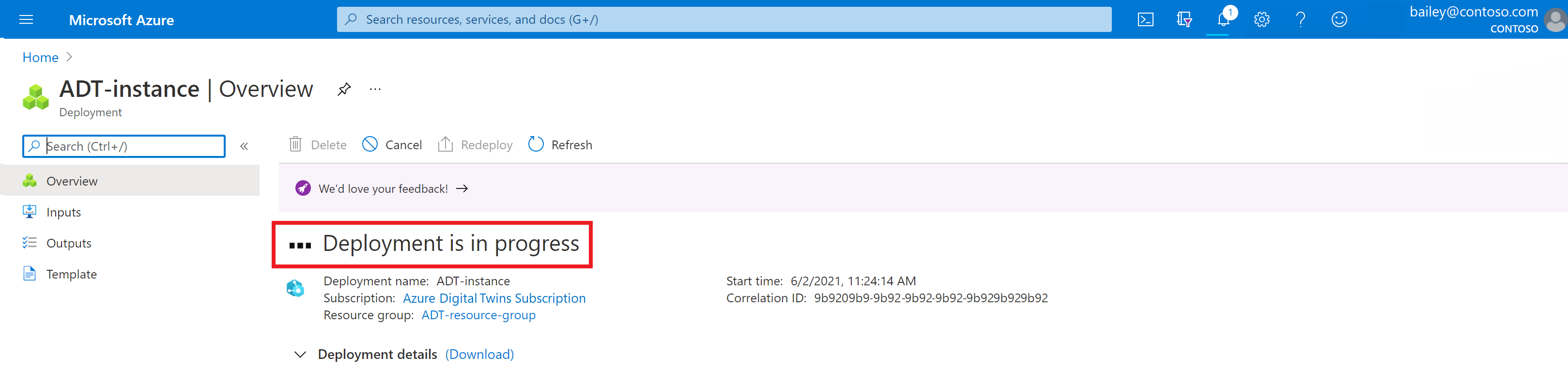
Wait for the page to say that your deployment is complete.
After deployment completes, use the Go to resource button to navigate to the instance's Overview page in the portal.
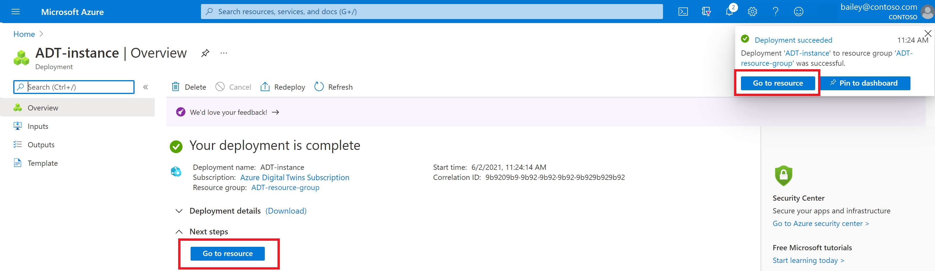
Next, take note of the instance's host name value to use later.

In this section, you use the Azure Digital Twins data simulator tool to generate sample models and twins to populate your instance. Then, you use the simulator to stream sample data to the twins in the graph.
Note
Models, twins, and simulated data are provided for you in this quickstart to simplify the process of creating an environment that you can view in 3D Scenes Studio. When designing your own complete Azure Digital Twins solution, you create models and twins yourself to describe your own environment in detail, and set up your own data flows accordingly.
This sample scenario represents a package distribution center that contains six robotic arms. Each arm has a digital twin with properties to track how many boxes the arm fails to pick up, along with the IDs of the missed boxes.
Navigate to the data simulator in your web browser.
In the Instance URL space, enter the host name of your Azure Digital Twins instance from the previous section. Set the Simulation Type to Robot Arms.
Use the Generate environment button to create a sample environment with models and twins. (If you already have models and twins in your instance, this action doesn't delete them, it just adds more.)

Scroll down and select Start simulation to start sending simulated data to your Azure Digital Twins instance. The simulation runs while this window is open and the Start simulation option is active.
You can view the models and graph that are created by using the Azure Digital Twins Explorer Graph tool. To switch to that tool, select the Graph icon from the left menu.

Then, use the Run Query button to query for all the twins and relationships that are created in the instance.

You can select each twin to view them in more detail.
To see the models that are uploaded and how they relate to each other, select Model graph.

Tip
For an introduction to Azure Digital Twins Explorer, see the quickstart Get started with Azure Digital Twins Explorer.
Next, create a new storage account and a container in the storage account. 3D Scenes Studio uses this storage container to store your 3D file and configuration information.
You also set up read and write permissions to the storage account. In order to set up these backing resources quickly, this section uses the Azure Cloud Shell.
Navigate to the Cloud Shell in your browser.
Run the following command to set the CLI context to your subscription for this session.
az account set --subscription "<your-Azure-subscription-ID>"
Run the following command to create a storage account in your subscription. The command contains placeholders for you to enter a name and choose a region for your storage account, and a placeholder for your resource group.
az storage account create --resource-group <your-resource-group> --name <name-for-your-storage-account> --location <region> --sku Standard_RAGRS
When the command completes successfully, you see details of your new storage account in the output. Look for the ID value in the output and copy it to use in the next command.

Run the following command to grant yourself the Storage Blob Data Owner on the storage account. This level of access allows you to perform both read and write operations in 3D Scenes Studio. The command contains placeholders for the email associated with your Azure account and the ID of your storage account that you copied in the previous step.
az role assignment create --role "Storage Blob Data Owner" --assignee <your-Azure-email> --scope <ID-of-your-storage-account>
When the command completes successfully, you see details of the role assignment in the output.
Run the following command to configure CORS for your storage account. This configuration is necessary for 3D Scenes Studio to access your storage container. The command contains a placeholder for the name of your storage account.
az storage cors add --services b --methods GET OPTIONS POST PUT --origins https://explorer.digitaltwins.azure.net --allowed-headers Authorization x-ms-version x-ms-blob-type --account-name <your-storage-account>
This command doesn't have any output.
Run the following command to create a private container in the storage account. Your 3D Scenes Studio files are stored here. The command contains a placeholder for you to enter a name for your storage container, and a placeholder for the name of your storage account.
az storage container create --name <name-for-your-container> --public-access off --account-name <your-storage-account>
When the command completes successfully, the output shows "created": true.
Now that all your resources are set up, you can use them to create an environment in 3D Scenes Studio. In this section, you create a scene and customize it for the sample graph that's in your Azure Digital Twins instance.
Navigate to the 3D Scenes Studio. The studio opens, connected to the Azure Digital Twins instance that you accessed last in the Azure Digital Twins Explorer. Dismiss the welcome demo.

Select the Edit icon next to the instance name to configure the instance and storage container details.

For the Azure Digital Twins instance URL, fill the host name of your instance from the Collect host name step into this URL: https://<your-instance-host-name>.
For the Azure Storage account URL, fill the name of your storage account from the Create storage resources step into this URL: https://<your-storage-account>.blob.core.windows.net.
For the Azure Storage container name, enter the name of your storage container from the Create storage resources step.
Select Save.

In this section, you create a new 3D scene, using the RobotArms.glb 3D model file you downloaded earlier in Prerequisites. A scene consists of a 3D model file, and a configuration file created for you automatically.
This sample scene contains a visualization of the distribution center and its arms. You connect this visualization to the sample twins you created in the Generate sample models and twins step, and customize the data-driven view in later steps.
Select the Add 3D scene button to start creating a new scene. Enter a Name and Description for your scene, and select Upload file.

Browse for the RobotArms.glb file on your computer and open it. Select Create.

Once the file is uploaded, you see it listed back on the main screen of 3D Scenes Studio.
Select the scene to open and view it. The scene opens in Build mode.

Next, you define an element in the 3D visualization and link it to a twin in the Azure Digital Twins graph you set up earlier.
Select any robotic arm in the scene visualization. This selection brings up the possible element actions. Select + Create new element.

In the New element panel, the Primary twin dropdown list contains names of all the twins in the connected Azure Digital Twins instance.
Select Arm1. This selection automatically applies the digital twin ID ($dtId) as the element name.
Select Create element.

The element now shows up in the list of elements for the scene.
Next, you create a behavior for the element. These behaviors allow you to customize the element's data visuals and the associated business logic. Then, you can explore these data visuals to understand the state of the physical environment.
Switch to the Behaviors list and select New behavior.

For Display name, enter Packing Line Efficiency. Under Elements, select Arm1.

Skip the Twins tab, which isn't used in this quickstart.
Switch to the Visual rules tab. Visual rules are data-driven overlays on your elements that you can configure to indicate the health or status of the element.
First, you set some conditions to indicate the efficiency of the packing line.
Select Add Rule.

Enter a Display name of Hourly pickups. Leave the Property expression on Single property and open the property dropdown list. It contains names of all the properties on the primary twin for the Arm1 element. Select PrimaryTwin.FailedPickupsLastHr. Then, select Add condition.

Next, you define some boundaries to indicate when the hourly pickups are missing too many packages. For this scenario, let's say an arm needs attention if it misses more than three pickups in an hour. Label the condition >3 missed pickups, and define a value range between 4 and Infinity (the min range value is inclusive, and the max value is exclusive). Assign an Element coloring of red. Select Save.

Select Add condition again, and create a condition labeled 1-3 missed pickups. Define a value range between 1 and 4, and assign an Element coloring of orange. Save the condition.
Select Add condition one more time, and create a condition labeled 0 missed pickups. Define a value range between 0 and 1, and assign an Element coloring of green. Save the condition.
After creating all three conditions, Save the new visual rule.

Next, create one more visual rule to display alerts for missed packages.
From the Visual rules tab, select Add Rule again.
![]()
Enter a Display name of PickupFailedAlert. Change the Property expression to Custom (advanced), enter a property of PrimaryTwin.PickupFailedAlert, and set the Type to boolean. This property selection references a boolean property on the arm twin that is set to True when a package pickup fails. Select Add condition.
![]()
Enter a Label of ${PrimaryTwin.PickupFailedBoxID} failed. Later, in the scene view, this label dynamically displays the value of the arm twin's string property PickupFailedBoxID, which holds an ID representing the box that the arm most recently failed to pick up. Set the Value to True and choose a Visual type of Badge. Set the Color to red and choose an Icon. Select Save to add the condition, and then select Save to save the visual rule.
![]()
You should now see both of your rules listed in the Visual rules tab.

Switch to the Widgets tab. Widgets are data-driven visuals that provide more context and data, to help you understand the scenario that the behavior represents. Here, you add two visual widgets to display property information for the arm element.
First, create a widget to display a gauge of the arm's hydraulic pressure value.
Select Add widget.

From the Widget library, select the Gauge widget and then Add widget.
In the New widget options, add a Display name of Hydraulic Pressure, a Unit of measure of m/s, and a single-property Property expression of PrimaryTwin.HydraulicPressure.
Set three value ranges so that values 0-40 appear one color, 40-80 appear in a second color, and 80-Infinity appear in a third color. (Remember that the min range value is inclusive, and the max value is exclusive.)

Select Create widget.
Next, create a widget with a link to a live camera stream of the arm.
Select Add widget. From the Widget library, select the Link widget and then Add widget.
In the New widget options, enter a Label of Live arm camera. For the URL, you can use the example URL http://contoso.armstreams.com/${PrimaryTwin.$dtId}. There's no live camera hosted at the URL for this sample, but the link represents where the video feed might be hosted in a real scenario.
Select Create widget.

The behavior options are now complete. Save the behavior by selecting Create behavior.

The Packing Line Efficiency behavior now shows up in the list of behaviors for the scene.
So far, you've been working with 3D Scenes Studio in Build mode. Now, switch the mode to View.

From the list of Elements, select the Arm1 element that you created. The visualization zooms in to show the visual element and displays the behaviors you set up for it.

Sometimes, an environment might contain multiple similar elements, which should all display similarly in the visualization (like the six different robot arms in this example). Now that you created a behavior for one arm and confirmed what it looks like in the viewer, this section shows you how to quickly add the behavior to other arms so that they all display the same type of information in the viewer.
Return to Build mode. Like you did in Create a scene element, select a different arm in the visualization, and select Create new element.

Select a Primary twin of Arm2 for the new element, then switch to the Behaviors tab.

Select Add behavior. Choose the Packing Line Efficiency behavior that you created in this quickstart.

Select Create element to finish creating the new arm element.
Switch to the View tab to see the behavior working on the new arm element. All the information you selected when creating the behavior is now available for both of the arm elements in the scene.

Tip
If you'd like, you can repeat the steps in this section to create elements for the remaining four arms, and apply the behavior to all of them to make the visualization complete.
This quickstart shows how to create an immersive dashboard for Azure Digital Twins data, to share with end users and increase access to important insights about your real world environment.
In the quickstart, you created a sample 3D scene to represent a package distribution center with robotic arms that pick up packages. This visualization was connected to a digital twin graph, and you linked an arm in the visualization to its own specific digital twin that supplied backing data. You also created a visual behavior to display key information about that arm when viewing the full scene, including information about any boxes the arm failed to pick up within the last hour.
In this quickstart, the sample models and twins for the factory scenario were quickly created for you, using the Azure Digital Twins Data simulator. When using Azure Digital Twins with your own environment, you create your own models and twins to accurately describe the elements of your environment in detail. This quickstart also used the data simulator to simulate "live" data driving digital twin property updates when packages were missed. When you use Azure Digital Twins with your own environment, ingesting live data is a process that you set up yourself according to your own environment sensors.
To clean up after this quickstart, choose which Azure Digital Twins resources you want to remove, based on what you want to do next.
If you want to continue using the Azure Digital Twins instance from this article, but clear out all of its models, twins, and relationships, run the following az dt job deletion CLI command:
az dt job deletion create -n <name-of-Azure-Digital-Twins-instance> -y
If you only want to delete some of these elements, you can use the az dt twin relationship delete, az dt twin delete, and az dt model delete commands to selectively delete only the elements you want to remove.
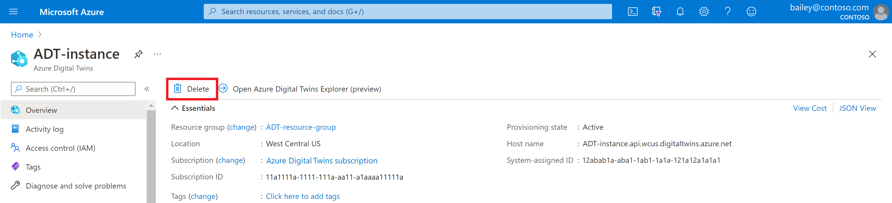
If you don't need your Azure Digital Twins instance anymore, you can delete it using the Azure portal.
Navigate back to the instance's Overview page in the portal. (If you already closed that tab, you can find the instance again by searching for its name in the Azure portal search bar and selecting it from the search results.)
Select Delete to delete the instance, including all of its models and twins.
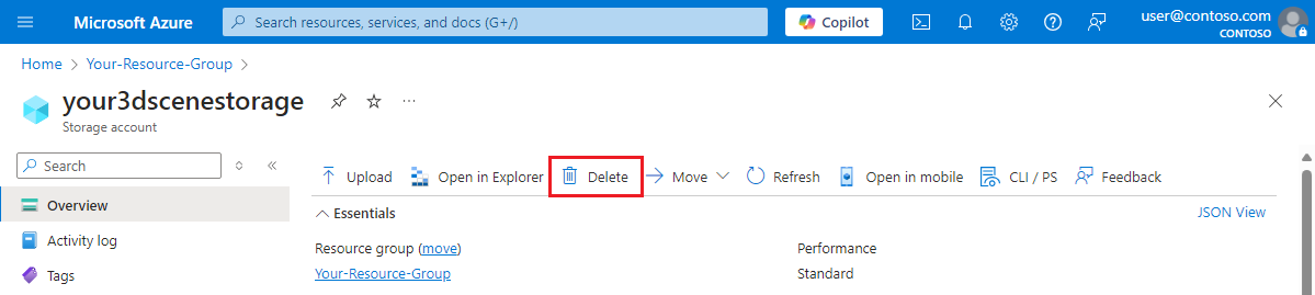
You can delete your storage resources by navigating to your storage account's Overview page in the Azure portal, and selecting Delete. This action deletes the storage account and the container inside it, along with the 3D scene files that were in the container.
You might also want to delete the downloaded sample 3D file from your local machine.
Next, continue on to the Azure Digital Twins tutorials to build out your own Azure Digital Twins environment.
Training
Certification
Microsoft Certified: Azure Virtual Desktop Specialty - Certifications
Plan, deliver, manage, and monitor virtual desktop experiences and remote apps on Microsoft Azure for any device.